Electronic amplifier type EV1M2-12/24 and EV1M2-24/48
Electronic amplifier type EV1M2-12/24 and EV1M2-24/48
Electronic amplifier type EV1M2-12/24 and EV1M2-24/48

You also want an ePaper? Increase the reach of your titles
YUMPU automatically turns print PDFs into web optimized ePapers that Google loves.
<strong>Electronic</strong> <strong>amplifier</strong> <strong>type</strong> <strong>EV1M2</strong>-<strong>12</strong>/<strong>24</strong> <strong>and</strong> <strong>EV1M2</strong>-<strong>24</strong>/<strong>48</strong><br />
for controlling proportional valves<br />
modular version to be connected via bolt-<strong>type</strong> terminals<br />
1. General<br />
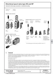
1.1 Brief description <strong>and</strong> block diagram<br />
The <strong>amplifier</strong> has a very high control accuracy <strong>and</strong> can be used to control a proportional<br />
solenoid.<br />
<strong>EV1M2</strong>-<strong>12</strong>/<strong>24</strong> from <strong>12</strong>V DC to <strong>24</strong>V CD <strong>and</strong> EV1 M 2-<strong>24</strong>/<strong>48</strong> from <strong>24</strong>V DC to <strong>48</strong>V DC.<br />
Main components:<br />
Permanent voltage regulator for generating 5V DC stabilized voltage<br />
Linear ramp generator (integrator) with separate adjustment of rise <strong>and</strong> fall times<br />
Dither oscillator<br />
Current-controlled, chopped terminal stage<br />
Main features:<br />
Imin <strong>and</strong> Imax st<strong>and</strong>ard <strong>and</strong> maximum current may be precisely adjusted by multi-gear<br />
potentiometer.<br />
Dither amplitude adjustable, dither frequency either 60 or <strong>12</strong>0 Hz.<br />
Power supply secured against incorrect pole connection<br />
Output protected against short cut <strong>and</strong> ground<br />
Dither signal superimposed on current output<br />
Enable/disable input (making the ramp ineffective)<br />
Improved EMC (electromagnetic compatibiIity)<br />
In conjunction with the card holder available as an accessory, this printed circuit with<br />
its compact dimensions fits conveniently on to 35 mm or 32 mm support rails in electric<br />
cabinets. Thanks to the modular design the connections on an 8-piece pin bar are<br />
clearly arranged <strong>and</strong> easily accessible from the front.<br />
Block diagram<br />
up<br />
U nom.<br />
down<br />
Enable/disable<br />
B 4, TP 3-TP6 are only in use when a coarse adjustment of the ramp times "rise" <strong>and</strong>/or "fall" on<br />
the multi-range-potentiometers is carried out by measuring the voltage (see sect. 4.2).<br />
1) Values in brackets valid for<br />
<strong>EV1M2</strong>-<strong>24</strong>/<strong>48</strong><br />
TP 1, TP 2 test points for measuring the coil (inductive) current 100 mV & 0.5 A (100 mV & 0.2A)<br />
This <strong>amplifier</strong> may be used for all HAWE proportional valves, see selection table in D 7810 Ü (over-view) . With electro-hydraulic<br />
remote control of PSL(V) directional valves as specified in D 7700-..., always make sure due to the twin proportional solenoids<br />
used for switch positions A <strong>and</strong> B that, depending on the direction of control <strong>and</strong> activation, there is an automatic, electric<br />
switchover to the respective solenoid, for example by a directional switch (micro-switch) in the remote control h<strong>and</strong> lever potentiometer,<br />
see typical circuit diagram in sect. 5.2.<br />
D 7831/1<br />
HAWE HYDRAULIK SE<br />
STREITFELDSTR. 25 • 81673 MÜNCHEN<br />
5<br />
<strong>Electronic</strong> <strong>amplifier</strong><br />
© 1993 by HAWE Hydraulik<br />
May 2007-00
D 7831/1 page 2<br />
2. Available versions , <strong>type</strong> coding<br />
A card holder, as specified in sect. 2.2, must be ordered as an accessory for each module as specified in sect. 2.1, since this is essential<br />
to securely fasten the module on the 35 mm or 32 mm support bar. The module board is very compact, there for it does not<br />
feature any pre-drilled holes, etc. for any other kind of fastening (for example on bold rods).<br />
2.1 Module<br />
Order coding: EV 1 M 2 -<strong>12</strong> /.<strong>24</strong>.<br />
Basic <strong>type</strong><br />
Single-action proportional<br />
solenoid control<br />
Module with bolt-<strong>type</strong> terminal<br />
connections<br />
<strong>12</strong>/<strong>24</strong> Supply voltage <strong>12</strong>/<strong>24</strong> VDC (nominal)<br />
<strong>24</strong>/<strong>48</strong> Supply voltage <strong>24</strong>/<strong>48</strong> VDC (nominal)<br />
Design <strong>and</strong> development status (internal code)<br />
2.2 Accessories for assembly<br />
Order coding: KM 7831 010<br />
Module card holder<br />
Internal drawing number<br />
2.3 Specifications<br />
2.3.1 General data<br />
Nomenclature<br />
<strong>Electronic</strong> <strong>amplifier</strong> for <strong>12</strong>V DC to <strong>24</strong>V DC bzw. <strong>24</strong>V DC to <strong>48</strong>V DC<br />
Design<br />
Module with 8-pin bolt connection rail<br />
Connection leads max. 1.5 mm 2<br />
Fastening<br />
Only via card holder (accessory) on 35 mm st<strong>and</strong>ardized support bars to DIN EN 50 022 or<br />
32 mm support bard to DIN EN 50 035<br />
Installation position<br />
Any<br />
Mass (weight)<br />
Module 45 g, card holder 40 g<br />
Type of protect. IEC70(CO) 13 IP 00<br />
Ambient temperature -20... + 50°C (up to 70°C at 75% of the max. power output IA )<br />
2.3.2 Electrical data<br />
<strong>EV1M2</strong>-<strong>12</strong>/<strong>24</strong><br />
<strong>EV1M2</strong>-<strong>24</strong>/<strong>48</strong><br />
Supply voltage U B 9 ... 32V DC 18 ... 65V DC<br />
max. perm. ripple factor W 10%<br />
Required filter capacitor C B 2200 µF per 1 A induction current<br />
Output voltage U A UB -1.2V DC, pulse-width modulated<br />
Output current I A max. 2.4 A short circuit proof protect. max. 1.5 A<br />
Setting range I min 0 ... 1.6 A 0 ... 1.5 A<br />
I max I min + (0 .. 2.4) A I min + (0...1.5) A<br />
Pre-setting: I min = 0 A; I max = 1 A<br />
No-load current I L max. 20 mA (own consumption)<br />
Voltage ranges U nom. adjustable, select 0 ... 5V DC, 0 .. 10V DC or 0 ... 15V DC<br />
Pre-setting: 0...5VDC<br />
Reference voltage U St 5V DC*4%<br />
load capacity max. 5 mA (stabilized voltage to supply potentiometer P 1)<br />
Input resistance R > 200 kΩ<br />
Recommended potentiom. P<br />
from 2 kΩ up tp 10 kΩ<br />
Ramp time rise-fall t R 0.1 .. 10s<br />
Ramp, linear rise time <strong>and</strong> fall time separately adjustable<br />
factory pre-setting: 0.1s for both (minimum)<br />
Enable/disable input<br />
TTL compatible or can be triggered with a contact<br />
(if blank release output)<br />
Dither frequency f 60 or <strong>12</strong>0Hz switchable; factory pre-setting: 60 Hz<br />
Dither amolitude<br />
0 ...750 mA (peak-to-peak)<br />
2.3.3 Electro-magnetic compatibility (EMC)<br />
The electro-magnetic compatibility has been tested by an accredited approval institute (criteria "B": Interference emission acc. to<br />
EN 50 081 <strong>and</strong> interference immunity acc. to EN 50 082). This EMC test doesn't relieve the user from the proper execution of a<br />
specified EMC check for his complete system (accordingly to regulation 89/336/EWG), since the test assemblies represent only a<br />
typical application. The following measures should be checked, if the EMC of the complete system must be strengthened further:<br />
' The required filter capacitor (see sect. 2.3.2) is not only necessary for flawless performance of the device, but also to ensure<br />
compliance of the EMC (wire bound interference emission)<br />
' The equipment should be installed in an metal cabinet (shielding)<br />
' All cables, leading in or out of the device should be kept as short as possible. The should be also be shielded <strong>and</strong> twisted in pairs.<br />
(This will reduce the antenna effect <strong>and</strong> increase the interference immunity).
D 7831/1 page 3<br />
3. Dimesions<br />
All dimensions are in mm, subject to change without notice !<br />
3.1 Printed circuit<br />
Direction of potentiometer rotation<br />
6<br />
7<br />
8<br />
9<br />
10<br />
Potentiometer ramp down time t down<br />
Potentiometer ramp up time t up<br />
Potentiometer dither amplitude<br />
Potentiometer basic current I min<br />
Potentiometer maximum current I max<br />
(25 turns)<br />
(25 turns)<br />
(25 turns)<br />
(25 turns)<br />
TP 1 + test point 1 for measuring current 1 )<br />
TP 2 - test point 2 for measuring current 1 )<br />
TP3 test point 3 to adjust ramp UP<br />
TP 4 test point 4 to adjust ramp DOWN<br />
TP 5-6 test points to adjust ramp times (see sect. 4.2)<br />
a<br />
max. 1.8 mm<br />
Range for securing <strong>and</strong> moving printed<br />
circuit (see also sect. 6.1)<br />
1) 100 mV & 0.5 A for <strong>EV1M2</strong>-<strong>12</strong>/<strong>24</strong><br />
100 mV & 0.2 A for <strong>EV1M2</strong>-<strong>24</strong>/<strong>48</strong><br />
B1 - B4 bridges (jumpers)<br />
Jumber placed<br />
Jumber open<br />
B 1, B2 <strong>and</strong> B3 see sect.5.1 <strong>and</strong> 5.2<br />
B4 is only for adjusting the ramp time<br />
(see section 4.2)<br />
Attention: B4 must otherwise be kept open !<br />
Plan of terminal connections:<br />
KI. 1 enable/disable input<br />
KI. 2 solenoid<br />
Kl. 3 zero Volt, ground for solenoid<br />
KI. 4 zero output, power<br />
KI. 5 zero Volt, signal ground<br />
KI. 6 reference input<br />
KI. 7 U St stabilized voltage (+5VDC)<br />
KI. 8 +U B supply voltage<br />
3.2 Printed circuit fitted in card holder<br />
See above for description of<br />
printed circuit<br />
Assembly of card holder see<br />
sect. 6<br />
St<strong>and</strong>ardized<br />
support bars
D 7831/1 page 4<br />
4. Instructions for assembly <strong>and</strong> installation<br />
4.1 Instructions for installation<br />
These instructions apply to the target voltage range of 5V using internal stabilized voltage U st = 5V.<br />
Bridges (jumpers) in position as delivered (for other, conceivable bridge positions see section 5.1)<br />
For assembly of printed circuit on card holder see section 6.<br />
Note: Any external target voltage fed into the system must not be or become negative. Negative voltage may lead to malfunction<br />
<strong>and</strong> destruction of the proportional <strong>amplifier</strong>s. When exceeding the maximum target voltage of 5, 10 or 15V DC, depending<br />
on the bridge circuit, the current set I max or I max oper becomes ineffective, i.e. it increases beyond the threshold set.<br />
When connecting wires more than 3 metres in length use wires with leads twisted in pairs in order to minimise interference (<strong>and</strong><br />
therefore to enhace resistance to interference).<br />
Maximum coil voltage I max set at the outlet may not in the long run exceed the I lim limit specified for the proportional solenoid, since<br />
otherwise the solenoid would be subjected to a thermal overload <strong>and</strong> might break down.<br />
Dither<br />
amplitude<br />
Ramp up time tu<br />
Ramp down time t d<br />
max. current I max<br />
min.current I min<br />
F1 = 2,5 A mT fuse<br />
V 1 = Voltmeter for measuring coil current, 100 mV = 0.5 A<br />
(e.g. analogue or digital multimeter<br />
TP 1 = Test point 1<br />
TP2 = Test point 2<br />
P1 = Target value potentiometer 0.5-10 kΩ (e.g.4 kΩ, 2 W<br />
wire potentiometer, BÜRKLIN model Nr: 72E 422)<br />
1<br />
Amplifier connection:<br />
Proportional solenoid to pins 2 <strong>and</strong> 3<br />
Voltmeter V 1 to test points TP 1 <strong>and</strong> TP 2 (for measuring coil voltage)<br />
Target value potentiometer to pins 5, 6 <strong>and</strong> 7<br />
Supply voltage to pins 4 <strong>and</strong> 8<br />
2<br />
Set target value potentiometer for setting procedure (6) to minimum<br />
(0V) (ground side; pins 3, 4 <strong>and</strong> 5 are interconnected internally within<br />
printed circuit)<br />
3<br />
Pre-set dither amplitude (dither potentiometer in the middle)<br />
4<br />
Set ramp times t d <strong>and</strong> t u to minimum (turn ramp potentiometer anticlockwise<br />
until reaching the stop position. Multi-potentiometer<br />
(25 turns)<br />
5<br />
Switch on supply voltage<br />
Enable /<br />
Disable<br />
Supply from vehicle<br />
battery or mains<br />
converter (e.g.<br />
MNG 2,5-230/<strong>24</strong>)<br />
6<br />
Set I min potentiometer to minimum current Iminoper which, in accordance<br />
with the Q-l or |p-l curve of the proportional valve, corresponds<br />
to its lower, desired terminal function point in operation. See sect. 2.3.2<br />
for the adjustable I min range. Read I min oper from voltmeter V1 connected<br />
between test points TP 1 <strong>and</strong> TP 2, applying a current scale of<br />
see above<br />
Target value potentiometer<br />
P 1<br />
7<br />
Set target value potentiometer for step (o) to max. Read target value<br />
voltage off voltmeter V 2 (env. 5V)<br />
Proportional<br />
solenoid<br />
8<br />
9<br />
Set I max potentiometer to maximum current I max oper which, according<br />
to Q-l or |p-l curve of the proportional valve, corresponds to its upper,<br />
desired terminal function point in operation. See section 2.3.2 for<br />
the adjustable I max range<br />
Dither frequency f is set by the supplier to 55 Hz by means of open<br />
bridge B3. In most cases this is sufficient. However, it may be<br />
increased to 110 Hz by closing bridge B3, this setting being more appropriate<br />
for relatively small proportional valves (fitted, for example,<br />
with 25 " proportional solenoids)<br />
Adjust potentiometer P 1 to 0.5 x l max (inductance current). To determine<br />
the dither amplitude turn the ditherpotentiometer clockwise<br />
until vibrations on the proportional valve can just be felt but without it<br />
beginning to cause disturbances.<br />
10<br />
Set ramp times tu <strong>and</strong> td to the periods desired. In all cases ramp times<br />
cover the entire range of output current I A . To speed up the setting-up<br />
procedure see section 4.2<br />
11<br />
Check the function parameters set: I min oper (item 6 ) at U tar = 0V DC;<br />
Imaxoper (item 8 ) at U tar = 5VDC, dither amplitude (item 9 ) <strong>and</strong><br />
ramp times (item 10 ). If necessary, repeat setting procedures.
D 7831/1 page 5<br />
<strong>12</strong> Further instructions<br />
In the event of interference during the setting procedure or when commissioning, check mains supply. In the case of rectified<br />
bridge configuration, check whether anelectrolyte filter capacitor of at least 2200µF/A coil voltage is switched parallel to the<br />
supply voltage.<br />
Is the supply voltage for the proportional <strong>amplifier</strong> sufficient? Under load it should be at least approx. 2V DC higher than would<br />
be required to generate the maximum current set of Imax oper with a warm solenoid coil without a proportional <strong>amplifier</strong>.<br />
With the proportional <strong>amplifier</strong> operating at a supply voltage of <strong>24</strong>V DC nominal, solenoid coils for <strong>12</strong>V may also be used, in which<br />
case the supply voltage is automatically converted of the <strong>12</strong>V level by the clocked terminal stage <strong>and</strong> with minimum loss. An<br />
important point to be observed in this case is that maximum permissible output current IA tor the proportional <strong>amplifier</strong> <strong>and</strong> limit<br />
current l Lim for the solenoid coil are not exceeded.<br />
Advantages: The proportional valve remains operative throughout the entire supply voltage range (e.g. from <strong>12</strong>-32V DC). In addition,<br />
the response times of the solenoid coil become shorter <strong>and</strong> the hydraulic system there-fore works more quickly.<br />
For higher supply voltages (i.e. for a <strong>EV1M2</strong>-<strong>24</strong>/<strong>48</strong>) a solenoid coil for <strong>24</strong>V DC should be used.<br />
4.2 Fast adjustment of ramp times<br />
The ramp times are normally adjusted by trial-<strong>and</strong>-error. This is the simplest method of adjustment, but it is also very time consuming.<br />
The relationship between ramp times <strong>and</strong> the rotary motions of the trimming potentiometer (25-turn) is not linear.<br />
The ramp times can be adjusted accurately (*15%) using a digital voltmeter (minimum 100 kΩ/V input impedance) <strong>and</strong> in conjunct.<br />
with the opposite diagram (refer also to sect. 3.1 <strong>and</strong> 4.1). The procedure is as follows:<br />
a<br />
b<br />
c<br />
Amplifier:<br />
Set jumber B4 <strong>and</strong> connect supply voltage to terminals 4 <strong>and</strong> 8<br />
Adjusting ramp rise time:<br />
Connect TP5 with 5 V (terminal 7), connect voltmeter between TP6.<br />
<strong>and</strong> TP3 read the required voltage for the ramp rise time from the<br />
diagram, set voltmeter to this value using the potentiometer.<br />
Adjusting ramp fall time:<br />
Connect TP5 with 0 V (terminal 5), connect voltmeter between TP6 <strong>and</strong><br />
TP4 , read the required voltage for the ramp fall time from the diagram<br />
set voltmeter to this value using the potentiometer.<br />
d Remove jumper B4 :<br />
Caution: If B4 jumper is set, the proportional <strong>amplifier</strong> will not work !<br />
t (sec)<br />
U (Volt)
D 7831/1 page 6<br />
5. Typical circuits<br />
5.1 Use of a proportional solenoid to control hydraulic valves<br />
Jumper position<br />
Target voltage range<br />
Dither frequency<br />
F1 = medium-fast fuse; for nominal see sect. 4.1 .<br />
P1 = target value potentiometer 10 kΩ, min 0.1 W<br />
Jumber B1 <strong>and</strong> B2 closed, other bridges open<br />
max. oper<br />
min. oper<br />
Example b: Operation with a target value switch for the<br />
two target values set I min oper <strong>and</strong> I max oper<br />
F1 = see example a above<br />
Jumper B1 <strong>and</strong> B2 closed, other jumper open<br />
Enable /<br />
Disable<br />
Jumper<br />
B1 - B2<br />
Supply<br />
Example a: Operation with an external target value potentiometer<br />
Proportional<br />
solenoid<br />
Not used<br />
Example c: Operation with a priority-dependant<br />
target value switch for four target<br />
values (relay switch)<br />
Typical example of operation:<br />
Fast gear 1 - K1 → P1<br />
Fast gear 2 - K2 → P2<br />
Slow gear - K3 → P3<br />
Stop - K1 → K2 → K3 → (<br />
F1 = see example a above<br />
Jumper B1 <strong>and</strong> B2 closed, other jumper open<br />
Example d: Operation with external target value<br />
power source from SPS, CNC or PC<br />
Important: Note the maximum load all owedfor<br />
the power source<br />
F1 = see example a above<br />
Rx = 250 Ω/ 0.5 W<br />
Jumper B1 <strong>and</strong> B2 closed, other jumper open<br />
Not used<br />
Example e: Operation with external target voltage<br />
from SPS, CNC or PC<br />
Important: Whenever the maximum target value<br />
voltage of 10 VDC (15 VDC) is exceeded,<br />
the maximum current set will<br />
continue to increase. Accordingly,<br />
the coil might overheat under excessive<br />
power <strong>and</strong> break down.<br />
F1 = see example a above<br />
Set jumper B2 for 10V DC, do not set jumper for<br />
15V DC voltage
D 7831/1 page 7<br />
5.2 Controlling hydraulic valves using one twin or two individual proportional solenoids for<br />
alternating operation<br />
Jumper<br />
B1 + B2<br />
closed<br />
This mode of operation requires a remote-control potentiometer for central<br />
alignment <strong>and</strong> side recognition of two positively connected direct. switches<br />
SB 1 <strong>and</strong> SB 2 for solenoid coils 1 <strong>and</strong> 2<br />
Enable<br />
Disable<br />
Power<br />
supply<br />
Example f: Controlling a proportional directional valve <strong>type</strong> PSL .. or PSV ..<br />
as specified in D 7700-..<br />
F1 = see example a above<br />
P1 = Potentiometer with fixed central alignment, 2x5 kΩ<br />
R = 31V varistor, such as a Siemens SIOV-S05K25 or SIOV-S10K25<br />
(against radio interference or excess voltage)<br />
Jumpers B1 <strong>and</strong> B2 (ref. voltage 5 VDC) are placed, B3 open<br />
S1 B <strong>and</strong> S2 B = directional switches are included in the control gear for<br />
one axle<br />
Proportional twin<br />
solenoid<br />
or<br />
pair of individual<br />
proportional<br />
solenoids<br />
6. Appendix<br />
6.1 Installation of printed circuit module on card holder<br />
Module<br />
(printed circuit)<br />
Card holder,<br />
left side<br />
Centrepiece<br />
Right<br />
side<br />
Rear trapezoid<br />
guide groove for<br />
support bar clamp<br />
All-round<br />
holding groove<br />
for module<br />
(printed circuit)<br />
Support bar<br />
clamp<br />
1<br />
2<br />
3<br />
4<br />
Fit together centrepiece of card holder <strong>and</strong> one of the two<br />
side pieces<br />
Insert support bar clamp into trapezoid groove at the back<br />
Insert conductor plate into end of all-round holding grove<br />
Insert remaining card holder side piece