SMC-Gold Manual - Heat-Timer® Corporation
SMC-Gold Manual - Heat-Timer® Corporation
SMC-Gold Manual - Heat-Timer® Corporation

You also want an ePaper? Increase the reach of your titles
YUMPU automatically turns print PDFs into web optimized ePapers that Google loves.
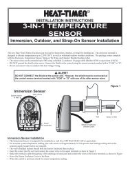
INSTALLATION/OPERATING INSTRUCTIONS<br />
<strong>SMC</strong><br />
Snow Melt Control for Under Slab <strong>Heat</strong>ing Systems<br />
Table of Contents<br />
Understanding the <strong>SMC</strong>......................................................................................................pg. 2<br />
<strong>SMC</strong> Control Panel..............................................................................................................pg. 3<br />
Installation..........................................................................................................................pg. 4<br />
Wiring Diagrams........................................................................................................pg. 5<br />
Mounting the Control..................................................................................................pg. 9<br />
Dip Switch Settings...................................................................................................pg. 9<br />
Installing the Sensors...............................................................................................pg. 10<br />
Wiring.....................................................................................................................pg. 11<br />
Initial Settings..........................................................................................................pg. 13<br />
Control Settings.................................................................................................................pg. 14<br />
Winter/Summer Switch.............................................................................................pg. 14<br />
Warm Weather Cutoff and Idle Set Point....................................................................pg. 14<br />
Cold Weather Cutoff..................................................................................................pg. 14<br />
Water Sensor Sensitivity...........................................................................................pg. 15<br />
Minimum Boiler Return (Reaction Time)......................................................................pg. 15<br />
Reaction Time..........................................................................................................pg. 15<br />
∆ T Max Slab Loop...................................................................................................pg. 15<br />
Minimum On Time....................................................................................................pg. 16<br />
Maximum Slab Supply Temperature...........................................................................pg. 16<br />
Alarm......................................................................................................................pg. 17<br />
Display Choices.......................................................................................................pg. 17<br />
References........................................................................................................................pg. 18<br />
Specifications..........................................................................................................pg. 18<br />
Meaning of Lights.....................................................................................................pg. 18<br />
Error Messages.......................................................................................................pg. 19<br />
Checking Sensors....................................................................................................pg. 20<br />
CORPORATION<br />
20 New Dutch Lane, Fairfield, NJ 07004<br />
973-575-4004 • FAX 973-575-4052<br />
http://www.heat-timer.com<br />
HT #059158 REV B<br />
1
UNDERSTANDING THE SNOW MELT CONTROL<br />
The <strong>Heat</strong>-Timer Snow Melt Control (<strong>SMC</strong>) is designed to control under slab heating systems which prevent accumulation<br />
of snow and ice on sidewalks, driveways, and other areas where buildups are undesirable. This is accomplished in two<br />
steps. First, the temperature and moisture of the slab are continuously monitored. Second, when moisture is detected<br />
and the temperature suggests there could be ice or snow, the heating system is activated and continues to run until the<br />
moisture is evaporated.<br />
The snow sensor is designed to become an integral part of the slab it will monitor. Therefore, it is specifically engineered<br />
for the extremes of heat and cold to which it will be subjected. Also, the sensor will withstand pressure and impact, such<br />
as might occur when a car drives over it. Despite this sturdy structure, the snow sensor will be able to read slab temperature<br />
within one degree, and sense even trace amounts of moisture.<br />
The snow sensor provides the information necessary to run the slab heating system. This system generally will include a<br />
heating plant, a heat exchanger, and a pump to move anti-freeze solution through the slab itself. The <strong>SMC</strong> can regulate<br />
the temperature of the anti-freeze solution to the slab by one of the following methods:<br />
• Modulating a 3-way valve to mix hot solution with solution returning from the slab<br />
• Modulating a 2-way valve to control the amount of steam entering the heat exchanger<br />
• Controlling a sequencing panel (SEQ6, SEQ6P or SEQ12) to stage multiple burners<br />
Typical application schematics are shown on pages 5-8.<br />
Whenever the outdoor temperature falls below the adjustable Warm Weather Cutoff, the heating plant will be activated.<br />
At this point, the slab will be warmed to an idle temperature by pumping warm anti-freeze solution through it. This will<br />
give the slab a head start on melting should precipitation occur. Once moisture is detected, the slab will be raised to an<br />
adjustable operating temperature. The temperature of the solution going to the slab is monitored to insure that at no time<br />
does too much heat enter the slab, causing stress on the slab and its components.<br />
The <strong>SMC</strong> includes several other features. The heating plant return temperature is monitored to reduce the possibility of<br />
thermal shock to the boiler. Also, an alarm is activated when any sensor fails to read correctly, if the slab is not receiving<br />
heat, and if the slab can not get up to temperature in 24 hours.<br />
2
R<br />
R<br />
MODEL <strong>SMC</strong><br />
To help simplify these instructions, sections of the control panel are keyed and<br />
referred to in the text by the following numbers.<br />
ACTIVE<br />
CAUTION!<br />
WIRING IN THIS<br />
BOX MUST BE<br />
RATED AT<br />
LEAST 120V<br />
LR 92903<br />
CURRENT STATUS<br />
INDICATORS<br />
WARM WEATHER<br />
CUTOFF<br />
MELTING<br />
IDLING<br />
ALARM<br />
2<br />
°F<br />
ATTENTION!<br />
LE CABLAGE<br />
RACCORDE DANS BOITE<br />
DOIT CONVENIR POUR<br />
UNE TENSION NOMINALE<br />
D'AU MOINS 120V<br />
1<br />
IDLE<br />
SET POINT<br />
°F<br />
BURNER<br />
SLAB<br />
PUMP<br />
3<br />
WINTER<br />
ALARM<br />
SLAB<br />
SUPPLY<br />
SUMMER<br />
0<br />
5 F<br />
0 0<br />
F<br />
ACTIVE<br />
PRESS TO DISPLAY<br />
T<br />
SLAB LOOP<br />
V<br />
MADE IN U.S.A.<br />
SLAB VALVE<br />
CLOSE OPEN<br />
SERIAL NO.<br />
4<br />
0 FAIRFIELD,<br />
N.J.<br />
0<br />
15 F<br />
SNOW MELT CONTROL<br />
10 F<br />
20 F<br />
COLD WEATHER CUTOFF<br />
5<br />
0<br />
6<br />
SLAB TEMP.<br />
BOILER<br />
RETURN<br />
0<br />
F<br />
SURFACE WATER<br />
DETECTED<br />
L<br />
E<br />
S<br />
S<br />
MODEL <strong>SMC</strong><br />
NORMAL<br />
ALARM RESET<br />
M<br />
O<br />
R<br />
E<br />
WATER SENSOR<br />
SENSITIVITY<br />
8<br />
7<br />
TEMPERATURE<br />
REGULATING EQUIPMENT<br />
LISTED<br />
723E<br />
OUTPUT RELAYS<br />
9<br />
60<br />
40<br />
80 100 30<br />
120<br />
140°F<br />
MINIMUM BOILER<br />
RETURN TEMP<br />
20<br />
40<br />
10 50°F<br />
T MAXIMUM<br />
MINIMUM ON TIME<br />
1 2 3 4 5<br />
6 7 8 9 10 11 12 13<br />
14 15 16<br />
0 1 2 4<br />
MUST BE<br />
CONNECTED<br />
NEUTRAL<br />
SUPPLY BURNER SLAB ALARM CLOSE OPEN<br />
PUMP<br />
PUMP<br />
SLAB<br />
OR VALVE<br />
VALVE<br />
CLASS I WIRING ONLY<br />
OUTPUTS:<br />
SUPPLY 115V 60HZ<br />
120VAC, 6A RESISTIVE; 1A PILOT DUTY<br />
POWER CONSUMPTION 20VA MAX. 15A TOTAL FOR ALL CIRCUITS<br />
USE COPPER WIRE ONLY<br />
LINE<br />
OUTPUT TERMINALS<br />
BRN BLK WHT GRN RED<br />
TO SNOW SENSOR<br />
COMM<br />
INPUT TERMINALS<br />
SLAB<br />
SUPPLY<br />
SLAB<br />
RETURN<br />
BOILER<br />
RETURN<br />
DO NOT APPLY ANY VOLTAGE TO THESE TERMINALS<br />
ROUTE SENSOR AND AUXILIARY WIRES THROUGH<br />
THIS KNOCKOUT ONLY<br />
425063-00 REV A<br />
3
GETTING THE INSTALLATION STARTED<br />
Following are four typical application schematics:<br />
• <strong>SMC</strong> with 3-way Valve and <strong>Heat</strong> Exchanger<br />
• <strong>SMC</strong> with 3-way Valve (Anti-freeze solution runs directly into the boiler)<br />
• <strong>SMC</strong> with Steam to Hot Water <strong>Heat</strong> Exchanger<br />
• <strong>SMC</strong> controlling a Sequencing Panel SEQ6, 6P or 12 (Anti-freeze solution runs directly into the boilers)<br />
Select the schematic which matches your application. If none of the schematics match your application, contact the<br />
factory for further assistance.<br />
NOTE: The application schematics are for illustration purposes only. They do not represent complete system diagrams<br />
and can not be interpreted as such.<br />
Installation of this control is simple if you follow the instructions carefully. The installation consists of four basic steps:<br />
• Locating and mounting the control<br />
• Locating and mounting the sensors<br />
• Wiring the power, input and output lines<br />
• Creating an initial pilot program of settings<br />
WARNING<br />
The <strong>Heat</strong>-Timer Model <strong>SMC</strong> is strictly an operating control; under no circumstances should it be<br />
used as a primary limit or safety control. The system must have its own certified limit and safety<br />
controls required by local codes. These are the responsibility of the installing contractor who must<br />
verify proper operation and correct any safety problems prior to starting the <strong>SMC</strong> installation.<br />
4
V<br />
<strong>SMC</strong> with 3-way Valve and <strong>Heat</strong> Exchanger<br />
CURRENT STATUS INDICATORS<br />
ACTIVE<br />
WARM WEATHER<br />
CUTOFF<br />
MELTING<br />
IDLING<br />
ALARM<br />
°F °F<br />
IDLE<br />
SET POINT<br />
0<br />
10 F<br />
5 0 F<br />
0 F<br />
COLD WEATHER CUTOFF<br />
ACTIVE<br />
PRESS TO DISPLAY<br />
0<br />
15 F<br />
SLAB TEMP.<br />
DF<br />
SERIAL NO.<br />
FAIRFIELD,<br />
<strong>SMC</strong><br />
SNOW MELT CONTROL<br />
20 0 F<br />
SURFACE WATER<br />
DETECTED<br />
NORMAL<br />
M<br />
O<br />
WATER SENSOR<br />
N.J.<br />
HEAT<br />
EXCHANGER<br />
BOILER<br />
RETURN SENSOR<br />
SLAB<br />
RETURN<br />
3-WAY<br />
MIXING VALVE<br />
SUPPLY<br />
SENSOR<br />
SENSOR<br />
SLAB<br />
SUPPLY<br />
SLAB LOOP<br />
SENSITIVITY<br />
BOILER<br />
RETURN<br />
WINTER SUMMER<br />
BURNER<br />
TERM 14-15-16<br />
MADE IN U.S.A.<br />
TERM 7-8<br />
SLAB<br />
SLAB VALVE<br />
BURNER PUMP ALARM CLOSE OPEN<br />
ALARM RESET<br />
TERM 4-5<br />
TERM 9-10<br />
80<br />
100 30<br />
20<br />
40<br />
60<br />
120<br />
40<br />
140DF 10 50°F<br />
MINIMUM BOILER<br />
RETURN TEMP<br />
T MAXIMUM<br />
MINIMUM ON TIME<br />
1<br />
2 3 4 5 6 7 8<br />
9<br />
10 11 12 13 14 15 16<br />
0 1<br />
MUST BE<br />
CONNECTED<br />
BRN BLK WHT GRN<br />
TO SNOW SENSOR<br />
SUPPLY BURNER SLAB ALARM CLOSE OPEN<br />
PUMP<br />
PUMP<br />
SLAB<br />
OR VALVE VALVE DO NOT APPLY ANY VOLTAGE TO THESE TERMINALS<br />
ROUTE SENSOR AND AUXILIARY WIRES THROUGH<br />
THIS KNOCKOUT ONLY<br />
BOILER RETURN<br />
SLAB RETURN<br />
SLAB SUPPLY SENSOR<br />
SNOW/ICE SENSOR<br />
SLAB<br />
SNOW/ICE<br />
SENSOR<br />
LINE<br />
NEUTRAL<br />
COMM<br />
SLAB<br />
SUPPLY<br />
SLAB<br />
RETURN<br />
BOILER<br />
RETURN<br />
RED<br />
0<br />
T<br />
L<br />
E<br />
S<br />
S<br />
2<br />
4<br />
R<br />
E<br />
5
<strong>SMC</strong> with 3-way Valve<br />
3-WAY<br />
MIXING VALVE<br />
CURRENT STATUS INDICATORS<br />
SERIAL NO.<br />
MELTING<br />
IDLING<br />
ALARM<br />
0<br />
10 F<br />
5 0 F<br />
0 0<br />
F<br />
COLD WEATHER CUTOFF<br />
ACTIVE<br />
0<br />
15 F<br />
FAIRFIELD,<br />
<strong>SMC</strong><br />
SNOW MELT CONTROL<br />
20 F 0 SURFACE WATER<br />
DETECTED<br />
N.J.<br />
ACTIVE<br />
NORMAL<br />
DF<br />
E<br />
°F °F<br />
SLAB TEMP.<br />
S<br />
S<br />
M<br />
O<br />
R<br />
E<br />
WARM WEATHER<br />
CUTOFF<br />
IDLE<br />
SET POINT<br />
SLAB<br />
SUPPLY<br />
PRESS TO DISPLAY<br />
T<br />
SLAB LOOP<br />
BOILER<br />
RETURN<br />
WATER SENSOR<br />
SENSITIVITY<br />
BOILER<br />
RETURN<br />
SENSOR<br />
WINTER SUMMER<br />
TERM 14-15-16<br />
MADE IN U.S.A.<br />
TERM 7-8<br />
SLAB<br />
SLAB VALVE<br />
BURNER PUMP ALARM CLOSE OPEN<br />
TERM 9-10<br />
ALARM RESET<br />
TERM 4-5<br />
80<br />
100 30<br />
20<br />
40<br />
60<br />
120<br />
40<br />
140DF 10 50°F<br />
MINIMUM BOILER<br />
RETURN TEMP<br />
T MAXIMUM<br />
MINIMUM ON TIME<br />
1<br />
2 3 4 5 6 7 8<br />
9<br />
10 11 12 13 14 15 16<br />
0 1<br />
MUST BE<br />
CONNECTED<br />
BLK WHT BRN GRN RED<br />
TO SNOW SENSOR<br />
SUPPLY BURNER SLAB ALARM CLOSE OPEN<br />
PUMP<br />
PUMP<br />
SLAB<br />
OR VALVE VALVE DO NOT APPLY ANY VOLTAGE TO THESE TERMINALS<br />
ROUTE SENSOR AND AUXILIARY WIRES THROUGH<br />
THIS KNOCKOUT ONLY<br />
BOILER RETURN<br />
SLAB RETURN<br />
SLAB SUPPLY SENSOR<br />
SNOW/ICE SENSOR<br />
BURNER<br />
SUPPLY<br />
SENSOR<br />
SLAB<br />
SLAB<br />
RETURN<br />
SENSOR<br />
SNOW/ICE<br />
SENSOR<br />
2<br />
L<br />
4<br />
V<br />
LINE<br />
NEUTRAL<br />
COMM<br />
SLAB<br />
SUPPLY<br />
SLAB<br />
RETURN<br />
BOILER<br />
RETURN<br />
6
<strong>SMC</strong> with Steam to Hot Water <strong>Heat</strong> Exchanger<br />
CURRENT STATUS INDICATORS<br />
SERIAL NO.<br />
MELTING<br />
IDLING<br />
ALARM<br />
0<br />
10 F<br />
5 0 F<br />
0 F<br />
COLD WEATHER CUTOFF<br />
ACTIVE<br />
0<br />
15 F<br />
FAIRFIELD,<br />
<strong>SMC</strong><br />
SNOW MELT CONTROL<br />
20 0 F<br />
SURFACE WATER<br />
DETECTED<br />
N.J.<br />
MODULATING<br />
STEAM VALVE<br />
( "V" PORT)<br />
SUPPLY<br />
SENSOR<br />
ACTIVE<br />
NORMAL<br />
WARM WEATHER<br />
CUTOFF<br />
°F °F<br />
IDLE<br />
SET POINT<br />
PRESS TO DISPLAY<br />
SLAB TEMP.<br />
DF<br />
M<br />
O<br />
R<br />
HEAT<br />
EXCHANGER<br />
WATER SENSOR<br />
SLAB<br />
SUPPLY<br />
WINTER SUMMER<br />
SLAB LOOP<br />
SENSITIVITY<br />
BOILER<br />
RETURN<br />
SLAB<br />
RETURN<br />
SENSOR<br />
MADE IN U.S.A.<br />
TERM 14-15-16 BURNER<br />
SLAB<br />
SLAB VALVE<br />
BURNER PUMP ALARM CLOSE OPEN<br />
ALARM RESET<br />
TERM 7-8<br />
80 100 30<br />
20<br />
40<br />
60<br />
120<br />
TERM 9-10<br />
40<br />
140DF 10 50°F<br />
MINIMUM BOILER<br />
RETURN TEMP<br />
T MAXIMUM<br />
MINIMUM ON TIME<br />
1<br />
2 3 4 5 6 7 8<br />
9<br />
10 11 12 13 14 15 16<br />
0 1<br />
MUST BE<br />
CONNECTED<br />
BRN BLK WHT GRN<br />
TO SNOW SENSOR<br />
SUPPLY BURNER SLAB ALARM CLOSE OPEN<br />
PUMP<br />
PUMP<br />
SLAB<br />
OR VALVE VALVE DO NOT APPLY ANY VOLTAGE TO THESE TERMINALS<br />
RED<br />
ROUTE SENSOR AND AUXILIARY WIRES THROUGH<br />
THIS KNOCKOUT ONLY<br />
SLAB RETURN<br />
SLAB SUPPLY SENSOR<br />
SNOW/ICE SENSOR<br />
SLAB<br />
SNOW/ICE<br />
SENSOR<br />
0<br />
T<br />
L<br />
E<br />
S<br />
S<br />
2<br />
4<br />
E<br />
V<br />
LINE<br />
NEUTRAL<br />
COMM<br />
SLAB<br />
SUPPLY<br />
SLAB<br />
RETURN<br />
BOILER<br />
RETURN<br />
1K Ohm to COM<br />
7
7<br />
8<br />
K1<br />
N<br />
H<br />
<strong>SMC</strong> Controlling a Sequencing Panel: SEQ6, SEQ6P or SEQ12<br />
Shown with 3 ON/OFF Boilers<br />
G<br />
120 VAC IN<br />
60 Hz<br />
STAGE 1<br />
STAGE 2<br />
LEAD<br />
1<br />
SUPPLY<br />
SLAB<br />
STAGE 3<br />
ACTIVE<br />
STAGE 1<br />
9<br />
COMM<br />
SENSOR<br />
STAGE 2<br />
STAGE 4<br />
SLAB<br />
RETURN<br />
STAGE 3<br />
2<br />
SLAB<br />
SUPPLY<br />
BOILER<br />
RETURN<br />
STAGE 5<br />
4<br />
SENSOR<br />
STAGE 4<br />
STAGE 6<br />
TURN TO ADJUST<br />
STAGE 5<br />
°F °F<br />
PRESS TO DISPLAY<br />
STAGE 6<br />
IDLE<br />
SET POINT<br />
WARM WEATHER<br />
CUTOFF<br />
SNOW/ICE<br />
SENSOR<br />
WATER SENSOR<br />
PRESS TO READ<br />
SENSITIVITY<br />
BOILER<br />
RETURN<br />
SLAB LOOP<br />
SLAB<br />
SUPPLY<br />
WINTER SUMMER<br />
SENSOR 1<br />
BURNER<br />
SEQ-6<br />
6 STAGE SEQUENCER<br />
MADE IN U.S.A.<br />
COM 2<br />
T<br />
V<br />
DF<br />
SLAB TEMP.<br />
SHIELD 3<br />
L<br />
E<br />
S<br />
S<br />
M<br />
O<br />
R<br />
E<br />
CURRENT STATUS INDICATORS<br />
0<br />
10 F<br />
5 0 F<br />
IDLING<br />
0 F<br />
COLD WEATHER CUTOFF<br />
ALARM<br />
ACTIVE<br />
ACTIVE<br />
0<br />
TERM 9 - 10<br />
K13<br />
K12<br />
K11<br />
SERIAL NO.<br />
N.J.<br />
FAIRFIELD,<br />
<strong>SMC</strong><br />
MELTING<br />
0<br />
15 F<br />
SNOW MELT CONTROL<br />
20 0 F<br />
SURFACE WATER<br />
DETECTED<br />
NORMAL<br />
TERM 14<br />
TERM 15<br />
+ 4<br />
SENSOR 5<br />
LEAD STAGE<br />
PRESSURE TEMP<br />
SLAB VALVE<br />
SLAB<br />
OPEN<br />
CLOSE<br />
ALARM<br />
BURNER PUMP<br />
ALARM RESET<br />
100 30<br />
80<br />
COM 6<br />
TERM 4<br />
TERM 5<br />
TERM 16<br />
40<br />
20<br />
120<br />
60<br />
PUMP<br />
PUMP<br />
Dry<br />
Contact<br />
Only<br />
SHUTDOWN<br />
140DF 10 50°F<br />
40<br />
T MAXIMUM<br />
MINIMUM BOILER<br />
RETURN TEMP<br />
BURNER<br />
MINIMUM ON TIME<br />
0 1<br />
10 11 12 13 14 15 16<br />
2 3 4 5 6 7 8<br />
SLAB<br />
RETURN<br />
BRN BLK WHT GRN RED<br />
TO SNOW SENSOR<br />
SUPPLY BURNER SLAB ALARM CLOSE OPEN<br />
PUMP<br />
PUMP<br />
SLAB<br />
OR VALVE VALVE DO NOT APPLY ANY VOLTAGE TO THESE TERMINALS<br />
NEUTRAL<br />
LINE<br />
AUXILIARY WIRES<br />
ROUTE SENSOR AND<br />
THROUGH<br />
THIS KNOCKOUT ONLY<br />
BURNER<br />
1K Ohm to COM<br />
SLAB RETURN<br />
SLAB SUPPLY SENSOR<br />
SNOW/ICE SENSOR<br />
8
FIRST STEP: MOUNT THE CONTROL<br />
Locate the control in an available site away from extreme heat and cold. The most logical place is in the mechanical<br />
equipment room or in an adjacent supervisory room, but away from any boilers and never in direct contact with a boiler or<br />
other hot surfaces.<br />
Avoid high temperatures: The control must be kept away from high temperatures. A location where room temperatures<br />
prevail is most preferable.<br />
Keep it unobtrusive: Avoid sites that are too public, where it might draw unwanted attention and tempt tampering.<br />
Keep it at eye level: Place it at about eye level so that the controls and signals are convenient to the operator.<br />
Once a location has been decided upon, find a suitable surface on which to mount the case. Mounting holes are provided<br />
on the back of the enclosure; but first you must remove the control panel in order to gain access to them. Use the<br />
following steps:<br />
1. Take off the gutter cover by loosening the screws at its bottom.<br />
2. Detach the control panel by removing the screw at the top center and loosening the two bottom ones.<br />
3. With the panel out, you are free to mount the enclosure, using the mounting holes on the back of the case.<br />
4. Mount the enclosure, using appropriate screws.<br />
Stop Here: Set the Back of the Panel<br />
Now while the control panel is out of the case is the time to activate the battery. Remove the battery insulation sheet by<br />
grasping the protruding end and pulling it out. This 5-year lithium battery is located on the back of the panel at its very<br />
top. Once activated it secures the control’s memory in case of a power outage. However, do not activate the battery<br />
unless you intend to power the control at once. It will drain down in about 100 days unless the control is powered.<br />
Set the dip switch for your application as shown below.<br />
Dip Switch Settings<br />
ON<br />
1 2 3 4 5 6 7 8<br />
Switches 1 through 5<br />
Not Used<br />
Switch 6<br />
Cold Weather Cutoff<br />
Switch 7<br />
Sequencer Enable<br />
Switch<br />
8<br />
Must<br />
be OFF<br />
ON<br />
6<br />
Enabled<br />
ON<br />
7<br />
Direct Control<br />
Mode<br />
ON<br />
6<br />
Disabled<br />
ON<br />
7<br />
Interface to SEQ6,<br />
SEQ6P, or SEQ12<br />
9
Install the Snow Sensor<br />
SECOND STEP: MOUNT THE SENSORS<br />
The location of the snow sensor (HT part #904200) must be carefully considered when the slab is being prepared or<br />
poured. The sensor should be placed in a location which represents the temperature of the majority of the slab. It should<br />
be placed away from any buildings, vents, or other heat sources. Also avoid placing the snow sensor in a sunny area<br />
when most of the slab is in shade, or vice versa. Another consideration when choosing the sensor location is to select a<br />
site where moisture is neither likely to run off or to puddle up. In the case of an area where the water runs off, the heating<br />
system will not run long enough to evaporate the majority of the water. In the case of the sensor being in a puddle, the<br />
heating system will have to run longer than necessary to detect that moisture has been evaporated. An exception to this<br />
later rule would be when the sensor site is specifically chosen to prevent snow or ice buildup in a known problem area.<br />
Equally importantly, the snow sensor must be level. If it is not, moisture will drain off the sensor and detection will not<br />
accurately occur. Also, a separate conduit should be run from the sensor location to the panel to house the sensor wires.<br />
This will provide easy access to the wires for service. These wires should not be run in conduit with any line voltage or<br />
other signal wires.<br />
Place the sensor socket in the chosen location and run the conduit feed to it. If more than 100 ft of wire is needed to reach<br />
the control panel location, install an appropriate junction box along the way. (Up to 400 ft of 14 gauge wire may be added<br />
to the supplied wire). Support the socket with a block of rock or stone to give it stability and level the surface of the<br />
dummy plug with the finished grade. (The plug has the same dimension as the snow sensor).<br />
After the concrete has cured, remove the plug and install the snow sensor using the o-ring and screws provided. Leave<br />
6-12" of wire in the socket cavity.<br />
Caution: The snow sensor is located outdoors and is likely to become covered with dirt, salt, or other substances<br />
which will adversely affect the moisture sensitivity of the sensor. It is important to check the snow sensor periodically<br />
to insure the surface of the sensor is clean. If the sensor is dirty, wipe or brush off the surface until the <strong>Heat</strong>-Timer logo<br />
and all other metal surfaces are clear.<br />
Install the Slab Supply and Slab Return Sensor<br />
The slab supply and return sensors must be immersion type sensors. These sensors will provide fast accurate information<br />
on changes in slab heating temperatures since they will be immersed in the anti-freeze solution. Make sure the<br />
supply sensor is approximately ten feet downstream from the heat source to avoid temperature fluctuations. The slab<br />
return sensor can be installed in any convenient location where the anti-freeze solution has returned from the slab.<br />
The immersions sensors (HT part #904024) thread into any existing 1/2"NPT, 3/8" I.D. well. If there are no existing wells,<br />
then it is necessary to install a well (HT part #904001) in both the slab supply and slab return. The wires for the immersion<br />
sensor can be extended up to 500' by simply splicing to the existing wire.<br />
Caution: Use shielded 2-conductor cable (#22 AWG minimum or to meet local codes) Belden #8760 shielded cable or<br />
equivalent. Avoid running the sensor wires in the same conduit with line voltage wiring.<br />
Install the Boiler Return Sensor<br />
Monitoring the return temperature to the boiler will help to preventing thermal shock stress to the boiler. This sensor<br />
should be an immersion type sensor (HT part #904024) and be installed in the same manner as the slab supply and return<br />
sensors (described above).<br />
WARNING<br />
If the Boiler Return Sensor is not being installed, it is necessary to place a 1,000 Ohm (1KΩ) resistor from the terminal<br />
BOILER RETURN to COM. If this resistor is not installed, the alarm output will constantly be activated and the slab<br />
pumps will shut down.<br />
10
THIRD STEP: WIRE THE TERMINALS<br />
Wiring the Power<br />
Terminal #1 is for earth ground. It must be connected. Terminal #2 is for line voltage and #3 is for neutral.<br />
Wiring the SUPPLY PUMP OR VALVE and BURNER (Without SEQ panel)<br />
First check the typical application drawings (pgs. 5-8) to determine which outputs should be connected for your application.<br />
Terminals #7 and #8 are normally open and should be wired in series with the limit circuit of the burner. If connecting<br />
to a supply pump, wire Terminals #4 and #5 to the pump starter. If connecting to a valve, Terminal #5 is common,<br />
Terminal #4 is open, and Terminal #6 is close.<br />
NOTE: Terminals #4 through #8 are all controlled by the BURNER RELAY. They are DRY CONTACTS only. When the<br />
BURNER RELAY closes, #4 and #5 will close, as will #7 and #8. The normally closed contacts #5 and #6 will open. The<br />
relay is rated for 6A at 120VAC.<br />
Wiring the SLAB PUMP<br />
Wire Terminals #9 and #10 to the slab pump starter.<br />
NOTE: Terminals #9, #10, and #11 provide a normally open and normally closed output. They are DRY CONTACTS ONLY.<br />
These are controlled by the SLAB PUMP RELAY. The relay is rated for 6A at 120VAC.<br />
Wiring the SLAB VALVE (Without SEQ panel)<br />
Terminals #14, #15, and #16 provide floating control for the slab temperature control valve. This output can modulate<br />
either a 2-way or a 3-way control valve (see pgs. 5-8 for typical applications).<br />
NOTE: These connections are controlled by the SLAB VALVE CLOSE and the SLAB VALVE OPEN RELAYS. They are<br />
DRY CONTACTS ONLY. The relays are rated for 6A at 120VAC.<br />
Wiring to a SEQ panel (SEQ6, SEQ6P or SEQ12)<br />
<strong>SMC</strong> Output Terminal Connect To SEQ Input Terminal<br />
14 1<br />
15 2<br />
4 5<br />
5 6<br />
16 7<br />
Wiring the ALARM<br />
Terminals #12 and #13 are normally open contacts to run an alarm if the slab does not get heat, if the slab does not reach<br />
temperature in 24 hours, or if there is a fault in a sensor.<br />
NOTE: These contacts are controlled by the ALARM RELAY. They are DRY CONTACTS ONLY. The relay is rated for<br />
6A at 120VAC.<br />
Wiring Guidelines<br />
Bring wires through “knock-out” holes at the bottom of the enclosure. Do not attempt to bring wires in from the sides or<br />
top - this will interfere with the servicing of the control. Use electrical connectors such as you use with any junction box.<br />
Copper wire is specifically required by UL. Make sure the 120V line has a circuit breaker of its own.<br />
Caution: Choose a 120V power source with nothing else on the line. Do not put the control on the same line with the<br />
boiler power or other switches. This could result in the control being disconnected. The amount of current switched by<br />
the output relays must not exceed 1 amp inductive, 6 amps resistive at 120V. Comply with local codes, inserting<br />
external over-current protection. Make sure suitable branch circuit protection is provided.<br />
11
And Now: Wire the Input Terminals (Class 2)<br />
The class 2 terminals are for connecting the control to the snow sensor and the other temperature sensors.<br />
WARNING<br />
Never apply external voltage to the input terminals for the Snow Sensor, the Slab Supply, the Slab Return, or the Boiler<br />
Return. Permanent damage will occur, voiding the warranty.<br />
Draw the wires from the Snow Sensor and other temperature sensors through the knockout holes directly under the<br />
terminals on the right side of the case and connect them to the appropriate terminal lugs described below. Always use the<br />
knock-out holes.<br />
The snow sensor wires go to the left five terminals. Connect the colored wires to the marked terminals, that is the brown<br />
wire to BRN, the black wire to BLK, the white wire to WHT, and green wire to GRN, and the red wire to RED.<br />
For the remaining three sensors (only two if the boiler return is not being monitored), one side of each sensor wire must<br />
go the terminal marked COM or BLK. The other wire from the slab supply sensor goes to the terminal marked SLAB<br />
SUPPLY. The other wire from the slab return sensor goes to the terminal marked SLAB RETURN. Finally, the other wire<br />
from the boiler return sensor goes to the terminal marked BOILER RETURN.<br />
WARNING<br />
If the Boiler Return Sensor is not being installed, it is necessary to place a 1KΩ resistor from the terminal BOILER<br />
RETURN to COM. If this resistor is not installed, the alarm output will constantly be activated and the slab pumps will<br />
shut down.<br />
Installation Tests for Sensor Wiring<br />
About 15 to 30 seconds after the control is powered, the slab temperature should appear on the display. If the display<br />
reads OPN this means the <strong>SMC</strong> does not see the snow sensor connected. This could mean that the snow sensor has not<br />
been hooked to the correct terminals or that there is a break or OPeN somewhere in the run of the wires to the terminals. If<br />
the display reads SHT this means the <strong>SMC</strong> sees a SHorT in the wires connected to the sensor. (See References pg. 20 for<br />
more information on testing sensors).<br />
To test the slab supply sensor, first be sure the Winter/Summer switch (Box 6 on pg. 3) is in the Winter position. Then<br />
push the button marked SLAB SUPPLY (Box 6). The display will show the temperature reading recorded by the SLAB<br />
SUPPLY sensor. As with the slab temperature sensor, an OPN or SHT in the display indicates there is a problem with the<br />
sensor.<br />
To test the slab return sensor, push the button marked ∆T SLAB LOOP (Box 6). If both the slab supply and slab return<br />
sensor have a valid readings, then the difference between the supply and return will be shown. Otherwise, the display<br />
will show —. Therefore, if the slab supply sensor shows a valid reading and the display shows — then there is a problem<br />
with the slab return sensor.<br />
Finally, to test the boiler return sensor, if it is being used, push the button marked BOILER RETURN (Box 6). If an OPN or<br />
SHT is displayed, there is a problem with the sensor.<br />
NOTE: If the boiler return sensor is not being used, a 1KΩ resistor must be placed across the terminals BOILER RETURN<br />
and COM. This 1KΩ resistor will display approximately 150°F when the button BOILER RETURN is pushed and held.<br />
12
FINAL STEP: INITIALIZING SETTINGS<br />
Once the control is mounted and wired, the next step is to get an initial program set. The following settings are recommended<br />
as a start-up program. The Control settings section (pg. 14) describes each setting in more detail. (The Box<br />
numbers referenced refer to the front panel diagram on pg. 3.)<br />
Initial Start-Up Settings (Without SEQ panel)<br />
1. Winter/Summer switch (Box 6) - set to Winter.<br />
2. Warm Weather Cutoff and Idle Set Point (Box 2)- The Warm Weather Cutoff should be set at 38° and the Idle Set Point<br />
set to 34°.<br />
3. Cold Weather Cutoff (Box 4) - set to 20°F.<br />
4. Water Sensor Sensitivity (Box 7)- Select the NORMAL position. If the red light marked Surface Water Detected (Box 7,<br />
directly above the knob) is on when there is no precipitation, then check the snow sensor and make sure it is clean.<br />
5. Minimum Boiler Return Temperature (Box 9) - This should be set according to the boiler manufacturers specifications.<br />
A safe starting point would be 140° unless the manufacturer specifies a lower return.<br />
6. ∆T Maximum Slab Loop (Box 9) - set to 20°F or check slab design characteristics to see if a higher ∆T can be selected.<br />
7. Minimum On Time (Box 9) - Set to 1 hour of run.<br />
8. Maximum Slab Supply - This should be set to the maximum temperature specified for the slab and/or tubing. To adjust<br />
the temperature, move the Winter/Summer switch (Box 6) to the Summer position and push and hold the SLAB SUPPLY<br />
button (also in Box 6). The SLAB TEMP display (Box 5) will show the Maximum Slab Supply set point. Adjust either<br />
the Warm Weather Cutoff or the Idle Set Point knob (while continuing to hold the SLAB SUPPLY button) to change the<br />
Maximum Slab Supply set point. When the desired temperature is displayed, release the SLAB SUPPLY button and<br />
switch the Winter/Summer switch back to Winter.<br />
Initial Start-Up Settings (With SEQ panel)<br />
To work with an SEQ output panel, Dip Switch 7 must be ON (see pg. 9).<br />
1. Winter/Summer switch (Box 6) - set to Winter.<br />
2. Warm Weather Cutoff and Idle Set Point (Box 2)- The Warm Weather Cutoff should be set at 38° and the Idle Set Point<br />
set to 34°.<br />
3. Cold Weather Cutoff (Box 4) - set to 20°F.<br />
4. Water Sensor Sensitivity (Box 7)- Select the NORMAL position. If the red light marked Surface Water Detected (Box 7,<br />
directly above the knob) is on when there is no precipitation, then check the snow sensor and make sure it is clean.<br />
5. Minimum Boiler Return Temperature (Box 9) - The function of this knob changes when interfacing to a SEQ panel. The<br />
knob becomes a Reaction Time adjustment. The Reaction time is the time between output stages being turned on or<br />
off. In the fully counterclockwise position, the Reaction time will be 1 minute. In the fully clockwise position, the<br />
Reaction time will be 10 minutes. Set the initial Reaction time to approximately 3 minutes or the position of the knob<br />
marked 60.<br />
6. ∆T Maximum Slab Loop (Box 9) - set to 20°F or check slab design characteristics to see if a higher ∆T can be selected.<br />
7. Minimum On Time (Box 9) - Set to 1 hour of run.<br />
8. Maximum Slab Supply - This should be set to the maximum temperature specified for the slab and/or tubing. To adjust<br />
the temperature, move the Winter/Summer switch (Box 6) to the Summer position and push and hold the SLAB SUPPLY<br />
button (also in Box 6). The SLAB TEMP display (Box 5) will show the Maximum Slab Supply set point. Adjust either<br />
the Warm Weather Cutoff or the Idle Set Point knob (while continuing to hold the SLAB SUPPLY button) to change the<br />
Maximum Slab Supply set point. When the desired temperature is displayed, release the SLAB SUPPLY button and<br />
switch the Winter/Summer switch back to Winter.<br />
WARNING<br />
If high temperatures will damage the slab or the slab components, a separate high limit controller must be installed to<br />
shut down the heating system if excessively high temperatures are being supplied to the slab.<br />
13
CONTROL SETTINGS<br />
The “start-up” list on the previous page serves to help you with a quick but incomplete guide to getting the control’s<br />
initial settings under way. All settings are keyed by number to correspond to the “start-up” list. All Box numbers refer to<br />
the front panel diagram on page 3.<br />
Here, on the following pages, are more detailed instructions on programming your <strong>SMC</strong>. You should learn the purpose<br />
and operation of each element of the control.<br />
1. WINTER/SUMMER SWITCH<br />
The winter-summer switch (in Box 6) must be in the WINTER position for the <strong>SMC</strong> to operate. The switch is used to turn<br />
the control off in summer while leaving displays active and preventing the back-up battery from draining down.<br />
2. WARM WEATHER CUTOFF AND IDLE SET POINT<br />
The Warm Weather Cutoff (in Box 2) actually performs two functions. When melting is not occurring, the Warm Weather<br />
Cutoff acts as an upper limit. If the slab temperature is warmer than the Warm Weather Cutoff, then melting will not begin<br />
even when moisture is detected. When the slab temperature falls below the Warm Weather Cutoff then the heating<br />
system will hold the slab at the Idle Set Point temperature until moisture is detected. A ±1F° differential is included in the<br />
Warm Weather Cutoff. This means that if the Warm Weather Cutoff is set for 38°F, the slab temperature must fall to 37°F<br />
before the heating system is activated. The heating system will remain activated until the slab temperature reaches 39°F.<br />
Once moisture has been detected and the slab temperature is below the Warm Weather Cutoff, melting begins. At this<br />
point, the Warm Weather Cutoff will serve as the set point at which the slab temperature will be held. That is, using the<br />
previous example, once a melting cycle has begun, the <strong>SMC</strong> will maintain the slab at 38° until the moisture is evaporated,<br />
or the minimum run time is exceeded, whichever comes last.<br />
The Idle Set Point is the temperature at which the slab will be held whenever melting is not occurring and the slab<br />
temperature is below the Warm Weather Cutoff. The Idle Set Point can be turned OFF, so the slab is not heated unless<br />
moisture is detected. The Idle Set Point can never be set higher than the Warm Weather Cutoff. If one attempts to raise<br />
the Idle Set Point above the Warm Weather Cutoff the display will not rise above the Warm Weather Cutoff. Therefore, to<br />
raise the Idle Set Point, it may first be necessary to raise the Warm Weather Cutoff.<br />
The range for the Warm Weather Cutoff is from 34°F to 44°F. The Idle Set Point range is from 20°F to 44°F and also has an<br />
OFF position, indicated by —. When the slab temperature rises above the Warm Weather Cutoff the red Warm Weather<br />
Cutoff ACTIVE light (Box 2) will come on.<br />
3. COLD WEATHER CUTOFF<br />
The Cold Weather Cutoff (in Box 4) prevents the slab from being heated when the slab temperature falls below a selected<br />
temperature. The setting for the Cutoff depends on two items, the size of the slab heating capacity and the type of<br />
precipitation that falls in colder weather. The limiting factor on the Cold Weather Cutoff must be the capacity of the<br />
system installed in the slab. As the slab becomes colder, the cost of heating the slab may well become prohibitive, and it<br />
may be impossible to raise the slab temperature enough to melt precipitation.<br />
The Cold Weather Cutoff can be set from 0°F to 20°F. If you wish to disable the Cold Weather Cutoff under all conditions,<br />
set dip switch 6 (pg. 9). When the slab temperature falls below the Cutoff, the red Cold Weather Cutoff ACTIVE light will<br />
come on and remain on until the slab temperature rises above the Cutoff. There is a ±1F° differential built into the Cold<br />
Weather Cutoff. For example, if the Cold Weather Cutoff is set for 15°F then the Cutoff ACTIVE light will come on at 14°F<br />
and will remain on until the temperature reaches 16°F.<br />
14
4. WATER SENSOR SENSITIVITY<br />
The Water Sensor Sensitivity knob (found in Box 7) adjusts the sensitivity of the snow sensor. The snow sensor is<br />
located outdoors and the surface must be kept clean. If it is not, the sensor may continuously detect moisture, even when<br />
none is present. The Water Sensor Sensitivity knob compensates for a dirty sensor.<br />
The <strong>SMC</strong> has several internal timers which delay the registering of moisture on the slab sensor when the <strong>SMC</strong> is switched<br />
to WINTER mode. Thus, even though the sensor has detected moisture, the red Surface Water Detected light may not<br />
come on immediately when the system is running.<br />
Therefore, when calibrating the Water Sensor sensitivity knob, switch the <strong>SMC</strong> into the Summer mode. In the Summer<br />
mode, the red Surface Water Detected light will not be delayed, and will turn on and off immediately based on the position<br />
of the knob and the information from the slab sensor. Once the Water Sensor Sensitivity knob has been calibrated, be<br />
sure to return the <strong>SMC</strong> into the Winter mode for proper operation.<br />
When moisture is detected by the snow sensor, the red LED marked SURFACE WATER DETECTED will light. This light<br />
should be used to test for the appropriate setting of the Water Sensor Sensitivity knob. If the snow sensor is known to<br />
be dry, then the LED should not be lit. Then when precipitation begins, the knob WATER SENSOR SENSITIVITY should<br />
be rotated very slowly clockwise from less to more sensitive until the LED lights up.<br />
NOTE: Once water has been detected on the slab, the <strong>SMC</strong> will “remember” this for four hours. That is, once moisture<br />
has been detected, if the slab temperature falls below the Warm Weather Cutoff or rises above the Cold Weather Cutoff,<br />
then melting will begin up to four hours after the moisture was detected. The fact that water has been detected will be<br />
shown by the red LED flashing.<br />
5. MINIMUM BOILER RETURN TEMP (Without SEQ panel)<br />
The Minimum Boiler Return Temperature knob (found in Box 9) is designed to reduce thermal shock on the boiler. The<br />
thermal shock of cold water returning to a hot boiler may shorten the life of the boiler. To avoid this undesirable situation,<br />
the Minimum Boiler Return can be set from 40° to 140°.<br />
When the temperature from the heating loop falls below the Minimum Boiler Return, the SLAB VALVE and SLAB PUMP<br />
are shut down to stop the heat transfer out of the system and to allow the boiler to recover. Then as the return temperature<br />
rises, the slab heating system is reactivated.<br />
5. REACTION TIME (SEQ panel)<br />
The knob marked Minimum Boiler Return Temperature (found in Box 9) changes function when the <strong>SMC</strong> is configured to<br />
control a SEQ panel (SEQ6, SEQ6P or SEQ12). To enter this mode, dip switch number 7 must be ON (see pg. 9).<br />
When the knob is turned fully counterclockwise, the Reaction Time is 1 minute. When the knob is turned fully counterclockwise,<br />
the Reaction Time is 10 minutes. In the center position (12 o’clock), the Reaction Time setting is 5.5 minutes.<br />
The Reaction Time controls the minimum run time for any stage. When a stage has been added, that stage can not be<br />
turned off, nor can another stage be activated, until at least half the Reaction Time has elapsed. The Reaction Time must<br />
be set to at least as long as the time it takes for a newly activated stage to start affecting the slab supply temperature.<br />
6. ∆T MAXIMUM SLAB LOOP<br />
The ∆T Maximum Slab Loop (found in Box 9) is designed to prevent too much heat from entering the slab at one time.<br />
When the amount of energy transferred to the slab exceeds a safe limit, the slab may be damaged. The ∆T is determined<br />
at the time the slab heating system is designed. It is a function of the size of the slab, the size of the heating system<br />
pump, and the size and spacing of the slab heating coils.<br />
To prevent this excess energy transfer, the temperature of the heating solution going out to the slab (Slab Supply) and the<br />
temperature of the solution returning from the slab (Slab Return) is monitored. This information provides a rough<br />
15
estimation of the amount of energy being transferred to the slab. The ∆T Maximum Slab Loop allows the operator to<br />
adjust the amount of energy entering the slab. The knob can be set from 10° to 50°F. When the difference between the<br />
Slab Supply and Slab Return exceeds this maximum value, the Slab Valve begins to close. The Slab Valve will close as<br />
much as is necessary to insure the temperature difference does not exceed the maximum value.<br />
7. MINIMUM ON TIME<br />
The Minimum On Time switch (found in Box 9) starts a timer once the slab heat is activated due to a melt condition. The<br />
<strong>SMC</strong> will continue melting until either all the moisture has evaporated off the sensor or until the Minimum On Time has<br />
been exceeded, whichever comes last. The Minimum On Time helps to insure the entire slab is free of moisture before<br />
melting is stopped. In addition, it protects the slab from rapid temperature variations which might occur if the slab heating<br />
system were turned on and off repeatedly. The Minimum On Time can be set for 0, 1, 2 or 4 hours of run.<br />
8. MAXIMUM SLAB SUPPLY TEMPERATURE<br />
The Maximum Slab Temperature need only be set once, when the <strong>SMC</strong> is first installed. The temperature selected should<br />
be determined by the manufacturer’s specification of the highest water temperature the slab heating system is rated for.<br />
To adjust the Maximum Slab Temperature, move the Winter/Summer switch (Box 6) to the Summer position. Then push<br />
and hold down the Slab Supply button (also in Box 6). The SLAB TEMP display (Box 5) will show the Maximum Slab<br />
Supply set point. Adjust either the Warm Weather Cutoff or the Idle Set Point knob (while continuing to depress the Slab<br />
Supply button) to change the Maximum Slab Supply set point. Rotate either knob clockwise to increase the value, or<br />
counterclockwise to decrease the value. When the temperature displayed is the desired maximum slab temperature set<br />
point, release the SLAB SUPPLY button and switch the Winter/Summer switch back to Winter.<br />
If the Slab Supply temperature exceeds the Maximum Slab Temperature, the <strong>SMC</strong> will send close signals to the motorized<br />
valve. The Burner and Slab Pump outputs will remain active if the slab temperature is below the Warm Weather Cutoff<br />
setting.<br />
WARNING<br />
If high temperatures will damage the slab or the slab components, a separate high limit controller must be installed to<br />
shut down the heating system if excessively high temperatures are being supplied to the slab.<br />
16
ADDITIONAL CONTROL FEATURES<br />
ALARM<br />
There are three reasons an alarm output is generated. The first is when the actual supply water temperature is more than<br />
20°F away from the target supply water for more than one hour. This would indicate there is a problem with the heating<br />
system which was preventing the supply water from getting hot.<br />
The second reason would be if the slab itself does not come up to the target temperature in 24 hours.<br />
The third reason is if there is a fault in any of the sensors being read by the <strong>SMC</strong>. To determine which sensor is at fault,<br />
use the following procedure:<br />
1. Look at the continuously displayed SLAB TEMP. If this reads OPN (for an OPeN circuit), or SHT (for a SHorTed<br />
circuit), then the problem lies in the snow sensor or the wires to the snow sensor.<br />
2. Push and hold the button (Box 6) SLAB SUPPLY. If this is a valid reading, then go ahead and check 3. Otherwise, if<br />
OPN or SHT is displayed, then the problem lies in the slab supply sensor.<br />
3. Push and hold the button (Box 6) ∆T SLAB LOOP. If — is displayed, then the problem lies with the Slab Return<br />
Sensor.<br />
4. Push and hold the boiler marked BOILER RETURN. If the display reads OPN or SHT then this is the source of the<br />
alarm. If this sensor is not being used, a 1KΩ resistor must be placed from the terminal BOILER RETURN to COM. If<br />
this 1KΩ resistor is in place, the display should show 150.<br />
5. If all these sensors display properly, then the snow sensor or the wiring to the snow sensor, has an internal fault that is<br />
causing the alarm.<br />
(See References pg. 20 for more complete information on testing the sensors.)<br />
The alarm activates a status light and a pair of contacts (terminals #12 and #13) which should be connected to a buzzer or<br />
other alarm to alert the users that an alarm condition has been sensed. To reset the alarm, which should be done only<br />
when the problem has been corrected, push the button marked ALARM RESET (found in Box 8).<br />
DISPLAY CHOICES<br />
The temperature constantly displayed (in Box 5) is the slab temperature as measured by the snow sensor. However, three<br />
other temperatures can be displayed by pushing the buttons in Box 6. To view the Slab Supply temperature, first make<br />
sure the Winter/Summer switch is the Winter position. (Otherwise the display will show the Maximum Slab Supply set<br />
point as explained on page 16.) Then push and hold the button marked Slab Supply. Instead of displaying the Slab<br />
temperature, the display in Box 5 will now show the slab supply solution temperature. Once the button is released, the<br />
display will return back to the Slab temperature.<br />
Similarly, press and hold the ∆T Slab Loop button (in Box 6) to show (in Box 5) the difference in temperature between the<br />
Slab Supply and Slab Return solution temperatures. This will give you a rough measure of the amount of energy presently<br />
being sent to the slab. Finally, push and hold the Boiler Return button (in Box 6) and the temperature of the Boiler<br />
Return water will be shown.<br />
17
REFERENCES<br />
Up to this point, we have been primarily concerned with the installation and operation of the control, but there may be<br />
times when you will want to have additional technical information. This section provides specifications, and troubleshooting<br />
hints.<br />
SPECIFICATIONS<br />
Voltage Input:<br />
120 VAC 60 Hz<br />
Power Consumption: 30 VA Max<br />
Outputs:<br />
2 S.P.D.T. and 4 N.O.<br />
Output Relay Ratings: 1 Amp inductive, 6 Amp Resistive at 120 VAC at 60 Hz<br />
Maximum Ambient Temp: 130° F.<br />
Sensor Indicating Ranges: -35°F to 255°F.<br />
Set Point Ranges:<br />
Warm Weather Cutoff: 34°F to 44°F<br />
Idle Set Point: OFF and 20°F to 44°F<br />
Cold Weather Cutoff: 0°F to 20°F<br />
Minimum Boiler Return Temperature: 40°F to 140°F<br />
Reaction Time (w/SEQ panels):<br />
1 to 10 min<br />
DT Maximum Slab Loop: 10F° to 50F°<br />
Maximum Slab Supply Water Temperature: 110°F to 190°F<br />
Power Backup:<br />
Lithium coin battery, 100 days minimum, 5 year life<br />
Enclosure:<br />
NEMA-1<br />
Dimensions: 4-5/8" x 12-1/4" x 12-3/8"<br />
MEANING OF LIGHTS IN BOX 1<br />
The three lights go ON and OFF - alone or in combination - during the system’s routine procedures. Following is a list to<br />
aid in troubleshooting.<br />
ALL LIGHTS OFF<br />
Nothing is happening. Neither melting nor idling is occurring, and all of the sensors are providing valid readings. The<br />
control may be switched to SUMMER, or the slab temperature may be above the Warm Weather Cutoff - Box 2 (in<br />
which case the red Warm Weather Cutoff Active light will be on), or the slab temperature may be below the Cold<br />
Weather Cutoff - Box 4 (in which case the red Cold Weather Cutoff Active light will be on).<br />
RED MELTING LIGHT IS ON<br />
The slab is being heated to the Warm Weather Cutoff temperature - Box 2. This should occur when the <strong>SMC</strong> is in<br />
Winter, the slab temperature is below the Warm Weather Cutoff, above the Cold Weather Cutoff, and moisture has<br />
been detected. If moisture is no longer being detected, and/or the slab temperature is warmer than the Warm Weather<br />
Cutoff, then the melting light may be on because the Minimum Run Time has not been exceeded.<br />
GREEN IDLE LIGHT IS ON<br />
The slab is being heated to the Idle Set Point temperature - Box 2. This should occur when moisture has not been<br />
detected, but the slab temperature is between the Warm and Cold Weather Cutoffs and the <strong>SMC</strong> is in WINTER.<br />
YELLOW ALARM LIGHT IS ON<br />
This is caused by one of the alarm conditions described on pg. 17. Once an alarm has been triggered, the alarm will<br />
remain activated even if the alarm condition has cleared and the control has returned to normal operation. To turn the<br />
alarm off, you must push the Alarm Reset button. If the yellow light comes right back on, then the alarm condition<br />
persists.<br />
18
ERROR MESSAGES<br />
Diagnostic Installation tests: The error messages in the chart below may appear when the control is powered. Whenever<br />
the <strong>SMC</strong> is powered up, it runs through a series of self diagnostic tests. If any of the tests fail, the messages in the chart<br />
below will be display.<br />
Caution: If there is a brown out condition, the <strong>SMC</strong> may register a failed Diagnostic test because the test could not be<br />
successfully completed. Therefore, if any of the following messages appear, power the unit down and back up. If THE<br />
error message does not appear again, the <strong>SMC</strong> is OK.<br />
DIAGNOSTIC MESSAGES<br />
This Message Means this Problem The Solution:<br />
(on main display)<br />
PPP ROM Error Replace CPU Board<br />
SSS RAM Error Replace CPU Board<br />
bbb Battery-backed RAM Replace CPU Board<br />
CCC Real time clock Replace CPU Board<br />
EEE EEPROM Error Replace CPU Board<br />
AAA Main Board A/D Replace Entire Control<br />
(on small display)<br />
INP Input Board A/D Replace Sensor Card<br />
OPN Sensor Circuit Open Check Sensor pg. 20<br />
SHT Sensor Circuit Shorted Check Sensor pg. 20<br />
Easy to Replace Circuit Boards<br />
The <strong>SMC</strong> includes a mother circuit board and two satellite boards. The larger of the two is the Central Processing Unit<br />
(CPU) board; the smaller one the sensor card. The sensor card simply snaps into place; the CPU board holds to the<br />
mother board by quarter-turn screws.<br />
CPU Board<br />
Mother Board<br />
1/4 Turn Fasteners<br />
Sensor Board<br />
19
CHECKING THE SENSORS<br />
To test the sensors, you will need a digital multimeter capable of reading ohms (Ωs). The BLACK wire serves as a<br />
common ground for all the sensors. The slab sensor is attached to the BLACK, BROWN, WHITE, RED, and GREEN<br />
wires. The Slab Supply sensor is attached to the BLACK and the terminal marked SLAB SUPPLY. The Slab Return sensor<br />
is attached to the BLACK and the terminal marked SLAB RETURN. Finally, the Boiler Return sensor is attached to the<br />
BLACK and the terminal marked BOILER RETURN. To test each set of wires you must first remove that set of wires from<br />
the <strong>SMC</strong> terminal strip. Then take an ohm reading across the detached wires leading out to the sensor. Be sure to return<br />
the wires to the correct terminals of the <strong>SMC</strong>, or the <strong>SMC</strong> will alarm constantly. The ohm reading for each of the sensors<br />
should be as follows:<br />
BROWN (SLAB SENSOR)<br />
This registers the slab temperature. The ohm reading should correspond to the<br />
ohm vs. temperature chart right. If the ohm reading appears to be incorrect, go<br />
to the precipitation sensor in the slab and see if it is being affected by sun, is<br />
covered with ice, or has other factors affecting it which would cause it to read a<br />
temperature different from the rest of the slab. If the sensor reads a higher<br />
resistance than is shown on the chart, or reads OPEN, the wires leading to the<br />
sensor may be broken or damaged. If the sensor reads a lower resistance than<br />
is shown on the chart, or reads SHORT, the wires to the panel may have become<br />
shorted together or exposed wires may be under water.<br />
WHITE (SLAB SENSOR)<br />
This registers the temperature of the slab heater. If the slab temperature is<br />
below 40 degrees and the <strong>SMC</strong> is idling or melting, the sensor should read from<br />
15,000 to 5,000Ω. Otherwise, the sensor should read approximately the same as<br />
the BROWN sensor described above.<br />
RED (SLAB SENSOR)<br />
This sensor should read from 50 to 100Ω. If the sensor reads OPEN, the wires<br />
leading to the sensor may be broken or damaged. If the sensor reads SHORT,<br />
the wires to the panel may have become shorted together.<br />
GREEN (SLAB SENSOR)<br />
If there is no precipitation, the sensor should read OPEN. If there is precipitation<br />
detected, the sensor should read from a few thousand ohms (2000Ω and up)<br />
to a couple of Meg ohms (less than 3,000,000Ω).<br />
TEMPERATURE<br />
(in degrees F)<br />
VALUE<br />
(in Ohms)<br />
0 42683<br />
10 31215<br />
20 23089<br />
25 19939<br />
30 17264<br />
35 14985<br />
40 13040<br />
45 11374<br />
50 9944<br />
55 8714<br />
60 7653<br />
70 5941<br />
80 4649<br />
90 3667<br />
100 2914<br />
110 2332<br />
120 1879<br />
130 1524<br />
140 1243<br />
150 1021<br />
160 842<br />
170 699<br />
180 583<br />
190 489<br />
200 412<br />
SLAB SUPPLY<br />
This registers the temperature of the solution being supplied to the slab. The ohm reading should correspond to the ohm<br />
vs. temperature chart right. If the sensor reads a higher resistance than is shown on the chart, or reads OPEN, the wires<br />
leading to the sensor may be broken or damaged. If the sensor reads a lower resistance than is shown on the chart, or<br />
reads SHORT, the wires to the panel may have become shorted together.<br />
SLAB RETURN<br />
This registers the temperature of the solution returning from the slab. The ohm reading should correspond to the ohm vs.<br />
temperature chart right. If the sensor reads a higher resistance than is shown on the chart, or reads OPEN, the wires<br />
leading to the sensor may be broken or damaged. If the sensor reads a lower resistance than is shown on the chart, or<br />
reads SHORT, the wires to the panel may have become shorted together.<br />
BOILER RETURN<br />
This registers the boiler return water temperature. The ohm reading should correspond to the ohm vs. temperature chart<br />
right. If the sensor reads a higher resistance than is shown on the chart, or reads OPEN, the wires leading to the sensor<br />
may be broken or damaged. If the sensor reads a lower resistance than is shown on the chart, or reads SHORT, the wires<br />
to the panel may have become shorted together. If the Boiler Return sensor is not installed, then a 1KΩ resistor must be<br />
installed in its place<br />
20
R<br />
<strong>SMC</strong> Slab Sensor<br />
Installation Addendum<br />
This addendum applies only to 6 Wire <strong>Heat</strong>-Timer <strong>SMC</strong> Slab Snow Sensor.<br />
When replacing the old Snow Melt Slab Sensor, you will find 6 wires instead of 5 wires. Follow the wire and terminal colors as per<br />
the bottom graph or table.<br />
Temperature Sensor Chart<br />
New Function Connect on panel to<br />
Black <strong>Heat</strong>er ground Black<br />
Red <strong>Heat</strong>er power Red<br />
White <strong>Heat</strong>er thermistor White<br />
Green Water detection Green<br />
Brown Slab thermistor Brown<br />
Blue Sesnor ground Black<br />
• The White and Blue wires registers the temperature of the slab heater. Its Ohm reading should be<br />
close to the temperature read on the Slab Temp display when control is in Melting or Idling stages.<br />
Use the Temperature Sensor Chart on the right to translate Ohms into temperature for that sensor.<br />
However, if control was not in Melting or Idling<br />
stages, the ohm reading should be between 5000Ω<br />
to 15,000Ω ohms.<br />
• The Green and Blue wires register percipitation.<br />
If there is no precipitation, the sensor should read<br />
OPEN. If there is precipitation detected, the sensor<br />
should read from 2000Ω to 3,000,000Ω ohms.<br />
(Make sure that the sensor is clean else it will give<br />
false percipitation reading.)<br />
• The Red and Black wires are the sensor heater. It<br />
should read from 90Ω to 110Ω ohms. If the sensor<br />
reads OPEN, the wires leading to the sensor may<br />
be broken or damaged. If the sensor reads SHORT,<br />
the wires to the panel may have become shorted<br />
together.<br />
• If all sensor readings are correct, contact <strong>Heat</strong>-<br />
Timer factory for replacing the <strong>SMC</strong> Input Card<br />
(HTC# 900097-00)<br />
WARNING<br />
If sensor readings corresponds<br />
to diagnosis, but <strong>SMC</strong> does not<br />
provide snow melting, replace Input<br />
Card #900097-00 only.<br />
New Snow-Melt<br />
Sensor Wiring<br />
BRN BLK WHT GRN RED<br />
Brown<br />
Black<br />
Blue<br />
White<br />
Green<br />
Red<br />
TEMPERATURE<br />
(in Degrees °F)<br />
Value<br />
(in Ohms Ω)<br />
-30 117720<br />
-20 82823<br />
-10 59076<br />
0 42683<br />
10 31215<br />
20 23089<br />
25 19939<br />
30 17264<br />
35 14985<br />
40 13040<br />
45 11374<br />
50 9944<br />
55 8714<br />
60 7653<br />
70 5941<br />
80 4649<br />
90 3667<br />
100 2914<br />
110 2332<br />
120 1879<br />
130 1524<br />
140 1243<br />
150 1021<br />
160 842<br />
170 699<br />
180 583<br />
190 489<br />
200 412<br />
210 349<br />
220 297<br />
230 253<br />
240 217<br />
250 187<br />
C O R P O R A T I O N<br />
R<br />
20 New Dutch Lane, Fairfield, NJ 07004 973-575-4004 • Fax 973-575-4052 • http://www.heat-timer.com<br />
059057-00 Rev. B
R<br />
<strong>SMC</strong> Sensor Troubleshoot<br />
Addendum<br />
This addendum applies only to <strong>Heat</strong>-Timer <strong>SMC</strong> Slab Snow Sensor .<br />
To test the Slab Snow Sensor upon getting sensor readings or erros or incorrect <strong>SMC</strong> behavior.<br />
Read all Sensor Values:<br />
• Copy all sesnor values from the panel screens to a sheet of paper.<br />
• Mark if the <strong>SMC</strong> is in Melting or Idle mode.<br />
• Mark if the Surface Water Detect Light is On or Off.<br />
• Disconnect all 5 wires from the panel. Remember to remove Alarm Relay prior to<br />
disconnecting sensors. After reconnecting sensors, reinsert the Alarm relay back into its socket.<br />
• Using a Digital Multimeter that is capable of reading Ohms Ω, measure the resistance between<br />
the Black wire and each of the other 4 wires.<br />
• The Brown and Black wires Ohm reading should correspond to the temperature read on the Slab<br />
Temp display. Use the Temperature Sensor Chart on the right to translate Ohms into temperature<br />
for that sensor. If the ohm reading appears to be incorrect, go to the precipitation sensor in the<br />
slab and see if it is being affected by sun, is covered with ice, or has other factors affecting it<br />
that would cause it to read a temperature different from the rest of the slab. If the sensor reads<br />
a higher resistance than is shown on the chart, or reads OPEN, the wires leading to the sensor<br />
may be broken or damaged. If the sensor reads a lower resistance than is shown on the chart, or<br />
reads SHORT, the wires to the panel may have become shorted together or exposed wires may<br />
be under water.<br />
• The White and Black wires registers the temperature of the slab heater. Its Ohm reading should<br />
be close to the temperature read on the Slab Temp display when control is in Melting or Idling<br />
stages. Use the Temperature Sensor Chart on the right to translate Ohms into temperature for<br />
that sensor. However, if control was not in Melting or Idling stages, the ohm reading should be<br />
between 5000Ω to 15,000Ω ohms.<br />
• The Green and Black wires registers percipitation. If there is no precipitation, the sensor<br />
should read OPEN. If there is precipitation detected, the sensor should read from 2000Ω<br />
to 3,000,000Ω ohms. (Make sure that the sensor is clean else it will give false percipitation<br />
reading.)<br />
• The Red and Black wires are the sensor heater. It should read from 50Ω to 100Ω ohms. If the<br />
sensor reads OPEN, the wires leading to the sensor may be broken or damaged. If the sensor<br />
reads SHORT, the wires to the panel may have become shorted together.<br />
• If all sensor readings are correct, contact <strong>Heat</strong>-Timer factory for replacing the <strong>SMC</strong> Input Card<br />
(HTC# 900097-00)<br />
WARNING<br />
If sensor readings corresponds to diagnosis, but <strong>SMC</strong> does not provide<br />
snow melting, replace Input Card #900097-00 only.<br />
• If any sensor readings are incorrect, contact <strong>Heat</strong>-Timer factory for replacing the <strong>SMC</strong> Snow<br />
Sensor (HTC# 904200-00) in addition to the Input Card (HTC# 900097-00).<br />
Temperature Sensor Chart<br />
TEMPERATURE<br />
(in Degrees °F)<br />
Value<br />
(in Ohms Ω)<br />
-30 117720<br />
-20 82823<br />
-10 59076<br />
0 42683<br />
10 31215<br />
20 23089<br />
25 19939<br />
30 17264<br />
35 14985<br />
40 13040<br />
45 11374<br />
50 9944<br />
55 8714<br />
60 7653<br />
70 5941<br />
80 4649<br />
90 3667<br />
100 2914<br />
110 2332<br />
120 1879<br />
130 1524<br />
140 1243<br />
150 1021<br />
160 842<br />
170 699<br />
180 583<br />
190 489<br />
200 412<br />
210 349<br />
220 297<br />
230 253<br />
240 217<br />
250 187<br />
C O R P O R A T I O N<br />
R<br />
20 New Dutch Lane, Fairfield, NJ 07004 973-575-4004 • Fax 973-575-4052 • http://www.heat-timer.com<br />
059038-00 Rev. A