Central ventilation with heat recovery unit KWL 250 - HELIOS ...
Central ventilation with heat recovery unit KWL 250 - HELIOS ...
Central ventilation with heat recovery unit KWL 250 - HELIOS ...

You also want an ePaper? Increase the reach of your titles
YUMPU automatically turns print PDFs into web optimized ePapers that Google loves.
<strong>Central</strong> <strong>ventilation</strong> <strong>with</strong> <strong>heat</strong> <strong>recovery</strong> <strong>unit</strong> <strong>KWL</strong> <strong>250</strong><br />
Operation and installation instructions no. 91581<br />
INSTALLATION OF CONTROL CABLE<br />
The control cable should be shielded and not be placed parallel to the mains supply<br />
cable as interference may cccur.<br />
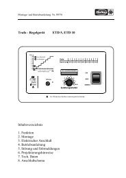
OPERATION – ADJUSTMENT<br />
The <strong>KWL</strong> <strong>250</strong> is to be controlled manually via the operation switch, which should<br />
be mounted on a convenient place in the house. The operation switch allows following<br />
functions:<br />
– right press button (fan symbol): the desired step for the air flow volume can be<br />
adjusted, the according light shows the chosen step:<br />
MIN (speed step 1) basic air flow, for less intake air needs<br />
NORMAL (speed step 2) normal air flow<br />
MAX (speed step 3) full R.P.M., for maximum intake air needs<br />
– left press button (+ symbol) only important in combination <strong>with</strong> electric <strong>heat</strong>er<br />
battery: The electric <strong>heat</strong>er battery can be switched on and off. When switched<br />
on, the <strong>heat</strong>er battery starts <strong>heat</strong>ing when the temperature is lower than the temperature<br />
pre set point (adjusted on the pot.)<br />
red light (!)<br />
blinking slow Filter needs to be changed ! (if filter monitor is installed)<br />
blinking fast The temperature monitor (Pic .3, No.2.2) for the <strong>heat</strong>er<br />
battery tripped.<br />
blinking constant Both messages appeared..<br />
green light (+) blinking, when availability of <strong>heat</strong>er element is switched<br />
on,<br />
yellow light (°C) Blinking, when electric <strong>heat</strong>er battery is in use.<br />
Speed step 2 can be adjusted to the size of the dewelling. Open the <strong>unit</strong> is to be<br />
opened. Then change the two connections, marked <strong>with</strong> speed step 2 at the<br />
transformer according to wiring diagram in the <strong>unit</strong>. Isolate from the mains supply<br />
before comencing this work all mains.<br />
Note: If the electrical supply of the <strong>KWL</strong> <strong>250</strong> is disconnected, the <strong>unit</strong> will restart<br />
automatically <strong>with</strong> basic air flow (speed step 1) and the availability of the <strong>heat</strong>er<br />
battery.<br />
N.B.: For good room climate and to avoid damage from condensation, the <strong>KWL</strong><br />
<strong>250</strong> should never be switched off apart from cleaning/maintenance work or possible<br />
faults.<br />
Settings on DIP-switch<br />
Switch- Standard- Function<br />
No. setting<br />
1 ON ON position: Electric <strong>heat</strong>er battery to be switched off<br />
during frost protection modus. (must not be OFF!)<br />
2 OFF ON position: Electric <strong>heat</strong>er battery to be switched off on<br />
speed step 1.<br />
3 OFF (only <strong>with</strong> timer) On position:<br />
Supply air to be lowered by 3 °C at night.<br />
(only if a <strong>heat</strong>er battery is used)<br />
4 OFF (only <strong>with</strong> timer) ON position:<br />
Air flow volume to be lowered on speed step 1 at night<br />
5 OFF –<br />
6 ON –<br />
Setting the electric <strong>heat</strong>er battery (<strong>KWL</strong> <strong>250</strong> EH)<br />
The pot for temperature preselection fot the <strong>heat</strong>er battery (pic.3, No.1) is placed<br />
on the extract air cover plate. This pot is factory set at 20 °C and can be adjusted<br />
as required for the supply air. Do not set higher than 25 °C. The <strong>heat</strong>ing battery is<br />
protected against over<strong>heat</strong>ing via a self resetting temperature cut out (pic. 3, No.<br />
2.1). This temperature cutout switches off automatically when the temperature of<br />
65°C has been reached. It switches back on automatically whenf the <strong>heat</strong>er battery<br />
has cooled down. As an additional safety control, a second, non self resetting<br />
thermostat (temperature cut out), switches off the whole <strong>unit</strong> automatically if a<br />
temperature of 80°C is exceeded. This thermostat can be manually reset by pressing<br />
the reset button, which is accessible by removing the white plastic lid.<br />
Regulating the water <strong>heat</strong>er battery (<strong>KWL</strong> <strong>250</strong> WW) (Picture 2)<br />
The progressive <strong>heat</strong>ing is via the built-in water <strong>heat</strong>er battery (18). The supply<br />
and return pipeing on site must be so routed or fully insulated supply to prevent<br />
frost damage. A thermostatic valve <strong>with</strong> remote sensor is to be fixed in the supply<br />
pipe of the <strong>heat</strong>er battery on site. The remote controller is to be fixed above the<br />
<strong>KWL</strong>-connecting spigot “supply air“ into the supply air ducting. Usung the remote<br />
sensor and the thermostatic valve in the water supply the supply air temperature<br />
is controlled. The thermostatic valve is not included and must be supplied and set<br />
on site.<br />
A water control system which is a Helios accessory (ref. WHST 300) is shown in<br />
picture 2. This provides a complete control for the water supply and return.<br />
ATTENTION: If the supply air ducting is to pass through cold areas Insulation must<br />
be applied to prevent temperature losses on before entering the room being supplied.<br />
Frost protection of the water <strong>heat</strong>er battery (Picture 2)<br />
Intake and extract ductwork must be insulated to avoid ice build up on the water<br />
<strong>heat</strong>er battery. Immediately after the water <strong>heat</strong>er battery there is a frost protection<br />
thermostat (20). If the temperature off the water <strong>heat</strong>er battery is lower than to +5<br />
°C the thermo sensor closes. This volt free contact of the thermostat is to be<br />
connected <strong>with</strong> the <strong>heat</strong>er control so that the shunt valve opens as soon as the<br />
<strong>heat</strong>er and circulating pump are switched off. This forced control avoids the ice<br />
build up on the water <strong>heat</strong>er battery. If the <strong>unit</strong> is switched off at any time in winter<br />
the warn water coil should be drained off to prevent frost damage to the coil.<br />
Frost protection of the <strong>heat</strong> exchanger battery:<br />
The sensor (Picture 3, No. 3) for frost protection is located in the extract air ducting.<br />
This sensor controls the supply air fan so that ice and frost can not build up in<br />
the extract air ducting or the <strong>heat</strong> exchanger. Warm air e.g. from the bathroom<br />
etc. contains high humidity that can condensate easily. Therefore the temperature<br />
in the <strong>heat</strong> exchanger must not drop so low that water freezes in it. When the outside<br />
temperature drops the extract temperature drops as well. If the temperature of<br />
the extract air is close to the freezing point, the supply air fan switches off for a<br />
certain period of time until the <strong>heat</strong> exchanger is warms up sufficienty. The frost<br />
protection thermostat is factory set and normally needs no adjustment.<br />
– Summer Service<br />
During the warmer months (apart from the <strong>heat</strong>ing period) it is not necessary to recover<br />
<strong>heat</strong>. The <strong>recovery</strong> battery can be replaced <strong>with</strong> a summer insert (Accessory <strong>KWL</strong>-<br />
SOE <strong>250</strong>, Ref. No. 0855). Through this the outside air enters directly into the house<br />
<strong>with</strong>out being warmed up. The temperature adjusting pot (<strong>KWL</strong> <strong>250</strong> EH) or the thermostat<br />
(<strong>KWL</strong> <strong>250</strong> WW) must be positioned on low temperature otherwise unnecessary<br />
<strong>heat</strong>ing will be the result. Remember to reset the thermostat the following autumn<br />
and replace the <strong>heat</strong> exchanger <strong>unit</strong> again.<br />
– Accessories, switches, controllers<br />
It is not admissible to use accessories which are not recommended by Helios, in<br />
case of damage this will lead to a loss of warranty. The use of an electronic or<br />
transformer speed controller is not permissible.<br />
CLEANING AND MAINTENANCE<br />
Isolate the <strong>unit</strong> from the electric supply before carring out any work on the <strong>unit</strong>.<br />
– Opening of door (Pic. 3, page 4)<br />
The door is secured <strong>with</strong> screws and can be opened after removing the screws.<br />
– Filter<br />
The <strong>unit</strong> filters are as follows:<br />
• Outside air: Prefilter G 3 Part.-No. 0043<br />
Finefilter F 5 Part.-No. 0044<br />
alternatively: (F 7, Part.-No. 0045, eg for persons <strong>with</strong> allergies)<br />
• Extract air: Prefilter G 3 Part.-No. 0043<br />
The outside air and the extract air filter are to be checked and changed regularly,<br />
depending on degree of pollution at least every 3 months. For hygiene reasons,<br />
the fine filter should be changed after every year at least. Check the correct the air<br />
flow direction when refitting the filter. In areas of heavy air pollution, a filter box<br />
(LFBR 125, Part.-No. 8577) should to be placed in an easily accessible area upstream<br />
of the <strong>unit</strong>. These filters must be regullary cleaned and changed.