Central ventilation with heat recovery unit KWL 250 - HELIOS ...
Central ventilation with heat recovery unit KWL 250 - HELIOS ...
Central ventilation with heat recovery unit KWL 250 - HELIOS ...

You also want an ePaper? Increase the reach of your titles
YUMPU automatically turns print PDFs into web optimized ePapers that Google loves.
<strong>Central</strong> <strong>ventilation</strong> <strong>with</strong> <strong>heat</strong> <strong>recovery</strong> <strong>unit</strong> <strong>KWL</strong> <strong>250</strong><br />
Operation and installation instructions no. 91581<br />
It is important for safety reasons and to ensure a satisfactory operation, that<br />
you read and observe this instruction fully before proceeding!<br />
RECEIPT<br />
The cardboard box conatains one of the following items, including a three step<br />
operation switch:<br />
<strong>KWL</strong> <strong>250</strong> Ref.-No. 850.001<br />
<strong>KWL</strong> <strong>250</strong> EH (<strong>with</strong> electric <strong>heat</strong>er battery) Ref.-No. 850.010<br />
<strong>KWL</strong> <strong>250</strong> WW (<strong>with</strong> water <strong>heat</strong>er batery) Ref.-No. 851.001<br />
Please check delivery immediately on receipt for accuracy and damage, please<br />
notifiy carrier immediately. In case of delayed notification, any possible claim may<br />
be void.<br />
STORAGE<br />
When storing for a prolonged time the following steps are to be taken to avoid damaging<br />
influences: protection by dry air and dustproof packing (plastic bags <strong>with</strong><br />
drying agent and moisture indicators). The storage area must be free of water, vibration<br />
and temperature variations.<br />
When storing for several years <strong>with</strong> non rotation of motor an inspection of the bearings<br />
<strong>with</strong> possible relubrication and an installation inspection in accordance <strong>with</strong><br />
VDE 0530 are absolutely necessary before starting operation. Damages due to<br />
improper storage, transportation or installation are not liable for warranty.<br />
OPERATION / USE<br />
The <strong>unit</strong> is designed to ventilate a combination of living rooms, bathrooms and kitchens<br />
in a single storey dewelling up to120 m 2 . The <strong>unit</strong> is equipped <strong>with</strong> a <strong>heat</strong><br />
<strong>recovery</strong> battery. It must not be connected to kitchen hoods or laboratory extract<br />
fans. The standard equipment allows a working temperature range from -20°C up<br />
to 40°C. For operation under difficult conditions, e.g. high humidity, long periods<br />
of standstill, high air pollution or through climatic (e.g. operating temperature over<br />
40°C), technical or electronic influences other than standard operations may not<br />
be suitable. For this reason please enquire and obtain operation release. A release<br />
by a third party is not valid.<br />
MODE OF ACTION<br />
In the <strong>heat</strong> exchanger the cold outside air and the warm extracted air "crosses over"<br />
<strong>with</strong>out touching. Through this exchange the energy of the warm air is tranfered to<br />
the incoming air. Additionally a thermostat controlled <strong>heat</strong>ing element warms up the<br />
inlet air (in extreme cold weather conditions) to the required temperature. The inlet<br />
air is directed to the living rooms and bedrooms through ducting and valves. The<br />
used air is extracted from the bathrooms, toilets and kitchens. It flows back to the<br />
fan via the ducting systems, transfering <strong>heat</strong> before being released into the open air.<br />
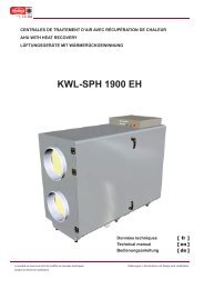
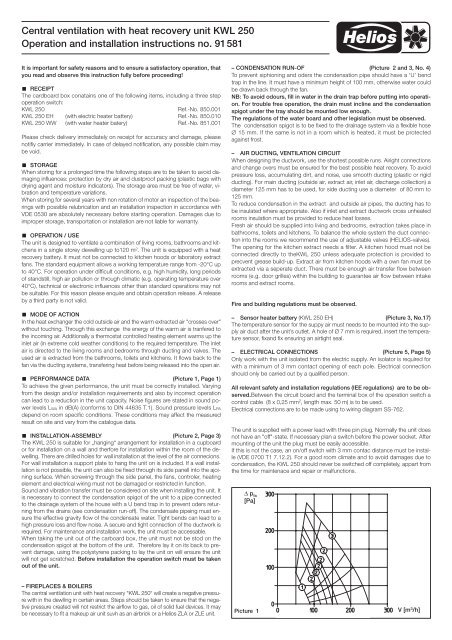
PERFORMANCE DATA (Picture 1, Page 1)<br />
To achieve the given performance, the <strong>unit</strong> must be correctly installed. Varying<br />
from the design and/or installation requireements and also by incorrect operation<br />
can lead to a reduction in the <strong>unit</strong> capacity. Noise figures are stated in sound power<br />
levels L WA in dB(A) (conforms to DIN 44635 T.1). Sound pressure levels L PA<br />
depend on room specific conditions. These conditions may affect the measured<br />
result on site and vary from the catalogue data.<br />
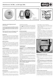
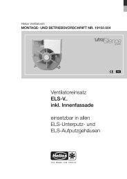
INSTALLATION-ASSEMBLY (Picture 2, Page 3)<br />
The <strong>KWL</strong> <strong>250</strong> is suitable for „hanging“ arrangement for installation in a cupboard<br />
or for installation on a wall and therfore for installation <strong>with</strong>in the room of the dewelling.<br />
There are drilled holes for wall installation at the level of the air connecions.<br />
For wall installation a support plate to hang the <strong>unit</strong> on is included. If a wall installation<br />
is not possible, the <strong>unit</strong> can also be fixed through its side panell into the ajoining<br />
surface. When screwing through the side panel, the fans, controler, <strong>heat</strong>ing<br />
element and electrical wiring must not be damaged or restricted in function.<br />
Sound and vibration transfer must be considered on site when installing the <strong>unit</strong>. It<br />
is necessary to connect the condensation spigot of the <strong>unit</strong> to a pipe connected<br />
to the drainage system of the house <strong>with</strong> a U bend trap in to prevent oders returning<br />
from the drains (see condensation run-off). The condensate pipeing must ensure<br />
the effective gravity flow of the condensate water. Tight bends can lead to a<br />
high pressure loss and flow noise. A secure and tight connection of the ductwork is<br />
required. For maintenance and installation work, the <strong>unit</strong> must be accessable.<br />
When taking the <strong>unit</strong> out of the carboard box, the <strong>unit</strong> must not be stod on the<br />
condensation spigot at the bottom of the <strong>unit</strong>. Therefore lay it on its back to prevent<br />
damage, using the polystyrene packing to lay the <strong>unit</strong> on will ensure the <strong>unit</strong><br />
will not get scratched. Before installation the operation switch must be taken<br />
out of the <strong>unit</strong>.<br />
– CONDENSATION RUN-OF (Picture 2 and 3, No. 4)<br />
To prevent siphioning and oders the condensation pipe should have a ‘U’ bend<br />
trap in the line. It must have a minimum height of 100 mm, otherwise water could<br />
be drawn back through the fan.<br />
NB: To avoid odours, fill in water in the drain trap before putting into operation.<br />
For trouble free operation, the drain must incline and the condensation<br />
spigot under the tray should be mounted low enough.<br />
The regulations of the water board and other legislation must be observed.<br />
The condensation spigot is to be fixed to the drainage system via a flexible hose<br />
∅ 15 mm. If the same is not in a room which is <strong>heat</strong>ed, it must be protected<br />
against frost.<br />
– AIR DUCTING, VENTILATION CIRCUIT<br />
When designing the ductwork, use the shortest possible runs. Airight connections<br />
and change overs must be ensured for the best possible <strong>heat</strong> <strong>recovery</strong>. To avoid<br />
pressure loss, accumulating dirt, and noise, use smooth ducting (plastic or rigid<br />
ducting). For main ducting (outside air, extract air, inlet air, discharge collection) a<br />
diameter 125 mm has to be used, for side ducting use a diameter of 80 mm to<br />
125 mm.<br />
To reduce condensation in the extract and outside air pipes, the ducting has to<br />
be insulated where appropriate. Also if inlet and extract ductwork cross un<strong>heat</strong>ed<br />
rooms insulation must be provided to reduce <strong>heat</strong> losses.<br />
Fresh air should be supplied into living and bedrooms, extraction takes place in<br />
bathrooms, toilets and kitchens. To balance the whole system the duct connection<br />
into the rooms we recommend the use of adjustable valves (<strong>HELIOS</strong>-valves).<br />
The opening for the kitchen extract needs a filter. A kitchen hood must not be<br />
connected directly to the<strong>KWL</strong> <strong>250</strong> unless adequate protection is provided to<br />
precvent grease build-up. Extract air from kitchen hoods <strong>with</strong> a own fan must be<br />
extracted via a seperate duct. There must be enough air transfer flow between<br />
rooms (e.g. door grilles) <strong>with</strong>in the building to guarantee air flow between intake<br />
rooms and extract rooms.<br />
Fire and building regulations must be observed.<br />
– Sensor <strong>heat</strong>er battery (<strong>KWL</strong> <strong>250</strong> EH) (Picture 3, No.17)<br />
The temperature sensor for the suppy air must needs to be mounted into the supply<br />
air duct after the <strong>unit</strong>’s outlet. A hole of Ø 7 mm is required, insert the temperature<br />
sensor, fixand fix ensuring an airtight seal.<br />
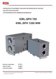
– ELECTRICAL CONNECTIONS (Picture 5, Page 5)<br />
Only work <strong>with</strong> the <strong>unit</strong> isolated from the electric supply. An isolator is required for<br />
<strong>with</strong> a minimum of 3 mm contact opening of each pole. Electrical connection<br />
should only be carried out by a qualified person.<br />
All relevant safety and installation regulations (IEE regulations) are to be observed.Between<br />
the circuit board and the terminal box of the operation switch a<br />
control cable (8 x 0,25 mm 2 , length max. 50 m) is to be used.<br />
Electrical connections are to be made using to wiring diagram SS-762.<br />
The <strong>unit</strong> is supplied <strong>with</strong> a power lead <strong>with</strong> three pin plug. Normally the <strong>unit</strong> does<br />
not have an "off"-state. If necessary plan a switch before the power socket. After<br />
mounting of the <strong>unit</strong> the plug must be easily accessible.<br />
If this is not the case, an on/off switch <strong>with</strong> 3 mm contac distance must be installe<br />
(VDE 0700 T1 7.12.2). For a good room climate and to avoid damages due to<br />
condensation, the <strong>KWL</strong> <strong>250</strong> should never be switched off completely, appart from<br />
the time for maintenace and repair or malfunctions.<br />
∆ p fa<br />
[Pa]<br />
– FIREPLACES & BOILERS<br />
The central <strong>ventilation</strong> <strong>unit</strong> <strong>with</strong> <strong>heat</strong> <strong>recovery</strong> “<strong>KWL</strong> <strong>250</strong>“ will create a negative pressure<br />
<strong>with</strong> in the dewlling in certain areas. Steps should be taken to ensure that the negative<br />
pressure created will not restrict the airflow to gas, oil of solid fuel devices. It may<br />
be necessary to fit a makeup air <strong>unit</strong> suvh as an airbrick or a Helios ZLA or ZLE <strong>unit</strong>.<br />
Picture 1<br />
V [m 3 /h]
<strong>Central</strong> <strong>ventilation</strong> <strong>with</strong> <strong>heat</strong> <strong>recovery</strong> <strong>unit</strong> <strong>KWL</strong> <strong>250</strong><br />
Operation and installation instructions no. 91581<br />
INSTALLATION OF CONTROL CABLE<br />
The control cable should be shielded and not be placed parallel to the mains supply<br />
cable as interference may cccur.<br />
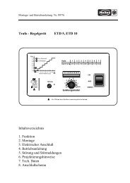
OPERATION – ADJUSTMENT<br />
The <strong>KWL</strong> <strong>250</strong> is to be controlled manually via the operation switch, which should<br />
be mounted on a convenient place in the house. The operation switch allows following<br />
functions:<br />
– right press button (fan symbol): the desired step for the air flow volume can be<br />
adjusted, the according light shows the chosen step:<br />
MIN (speed step 1) basic air flow, for less intake air needs<br />
NORMAL (speed step 2) normal air flow<br />
MAX (speed step 3) full R.P.M., for maximum intake air needs<br />
– left press button (+ symbol) only important in combination <strong>with</strong> electric <strong>heat</strong>er<br />
battery: The electric <strong>heat</strong>er battery can be switched on and off. When switched<br />
on, the <strong>heat</strong>er battery starts <strong>heat</strong>ing when the temperature is lower than the temperature<br />
pre set point (adjusted on the pot.)<br />
red light (!)<br />
blinking slow Filter needs to be changed ! (if filter monitor is installed)<br />
blinking fast The temperature monitor (Pic .3, No.2.2) for the <strong>heat</strong>er<br />
battery tripped.<br />
blinking constant Both messages appeared..<br />
green light (+) blinking, when availability of <strong>heat</strong>er element is switched<br />
on,<br />
yellow light (°C) Blinking, when electric <strong>heat</strong>er battery is in use.<br />
Speed step 2 can be adjusted to the size of the dewelling. Open the <strong>unit</strong> is to be<br />
opened. Then change the two connections, marked <strong>with</strong> speed step 2 at the<br />
transformer according to wiring diagram in the <strong>unit</strong>. Isolate from the mains supply<br />
before comencing this work all mains.<br />
Note: If the electrical supply of the <strong>KWL</strong> <strong>250</strong> is disconnected, the <strong>unit</strong> will restart<br />
automatically <strong>with</strong> basic air flow (speed step 1) and the availability of the <strong>heat</strong>er<br />
battery.<br />
N.B.: For good room climate and to avoid damage from condensation, the <strong>KWL</strong><br />
<strong>250</strong> should never be switched off apart from cleaning/maintenance work or possible<br />
faults.<br />
Settings on DIP-switch<br />
Switch- Standard- Function<br />
No. setting<br />
1 ON ON position: Electric <strong>heat</strong>er battery to be switched off<br />
during frost protection modus. (must not be OFF!)<br />
2 OFF ON position: Electric <strong>heat</strong>er battery to be switched off on<br />
speed step 1.<br />
3 OFF (only <strong>with</strong> timer) On position:<br />
Supply air to be lowered by 3 °C at night.<br />
(only if a <strong>heat</strong>er battery is used)<br />
4 OFF (only <strong>with</strong> timer) ON position:<br />
Air flow volume to be lowered on speed step 1 at night<br />
5 OFF –<br />
6 ON –<br />
Setting the electric <strong>heat</strong>er battery (<strong>KWL</strong> <strong>250</strong> EH)<br />
The pot for temperature preselection fot the <strong>heat</strong>er battery (pic.3, No.1) is placed<br />
on the extract air cover plate. This pot is factory set at 20 °C and can be adjusted<br />
as required for the supply air. Do not set higher than 25 °C. The <strong>heat</strong>ing battery is<br />
protected against over<strong>heat</strong>ing via a self resetting temperature cut out (pic. 3, No.<br />
2.1). This temperature cutout switches off automatically when the temperature of<br />
65°C has been reached. It switches back on automatically whenf the <strong>heat</strong>er battery<br />
has cooled down. As an additional safety control, a second, non self resetting<br />
thermostat (temperature cut out), switches off the whole <strong>unit</strong> automatically if a<br />
temperature of 80°C is exceeded. This thermostat can be manually reset by pressing<br />
the reset button, which is accessible by removing the white plastic lid.<br />
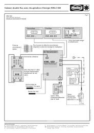
Regulating the water <strong>heat</strong>er battery (<strong>KWL</strong> <strong>250</strong> WW) (Picture 2)<br />
The progressive <strong>heat</strong>ing is via the built-in water <strong>heat</strong>er battery (18). The supply<br />
and return pipeing on site must be so routed or fully insulated supply to prevent<br />
frost damage. A thermostatic valve <strong>with</strong> remote sensor is to be fixed in the supply<br />
pipe of the <strong>heat</strong>er battery on site. The remote controller is to be fixed above the<br />
<strong>KWL</strong>-connecting spigot “supply air“ into the supply air ducting. Usung the remote<br />
sensor and the thermostatic valve in the water supply the supply air temperature<br />
is controlled. The thermostatic valve is not included and must be supplied and set<br />
on site.<br />
A water control system which is a Helios accessory (ref. WHST 300) is shown in<br />
picture 2. This provides a complete control for the water supply and return.<br />
ATTENTION: If the supply air ducting is to pass through cold areas Insulation must<br />
be applied to prevent temperature losses on before entering the room being supplied.<br />
Frost protection of the water <strong>heat</strong>er battery (Picture 2)<br />
Intake and extract ductwork must be insulated to avoid ice build up on the water<br />
<strong>heat</strong>er battery. Immediately after the water <strong>heat</strong>er battery there is a frost protection<br />
thermostat (20). If the temperature off the water <strong>heat</strong>er battery is lower than to +5<br />
°C the thermo sensor closes. This volt free contact of the thermostat is to be<br />
connected <strong>with</strong> the <strong>heat</strong>er control so that the shunt valve opens as soon as the<br />
<strong>heat</strong>er and circulating pump are switched off. This forced control avoids the ice<br />
build up on the water <strong>heat</strong>er battery. If the <strong>unit</strong> is switched off at any time in winter<br />
the warn water coil should be drained off to prevent frost damage to the coil.<br />
Frost protection of the <strong>heat</strong> exchanger battery:<br />
The sensor (Picture 3, No. 3) for frost protection is located in the extract air ducting.<br />
This sensor controls the supply air fan so that ice and frost can not build up in<br />
the extract air ducting or the <strong>heat</strong> exchanger. Warm air e.g. from the bathroom<br />
etc. contains high humidity that can condensate easily. Therefore the temperature<br />
in the <strong>heat</strong> exchanger must not drop so low that water freezes in it. When the outside<br />
temperature drops the extract temperature drops as well. If the temperature of<br />
the extract air is close to the freezing point, the supply air fan switches off for a<br />
certain period of time until the <strong>heat</strong> exchanger is warms up sufficienty. The frost<br />
protection thermostat is factory set and normally needs no adjustment.<br />
– Summer Service<br />
During the warmer months (apart from the <strong>heat</strong>ing period) it is not necessary to recover<br />
<strong>heat</strong>. The <strong>recovery</strong> battery can be replaced <strong>with</strong> a summer insert (Accessory <strong>KWL</strong>-<br />
SOE <strong>250</strong>, Ref. No. 0855). Through this the outside air enters directly into the house<br />
<strong>with</strong>out being warmed up. The temperature adjusting pot (<strong>KWL</strong> <strong>250</strong> EH) or the thermostat<br />
(<strong>KWL</strong> <strong>250</strong> WW) must be positioned on low temperature otherwise unnecessary<br />
<strong>heat</strong>ing will be the result. Remember to reset the thermostat the following autumn<br />
and replace the <strong>heat</strong> exchanger <strong>unit</strong> again.<br />
– Accessories, switches, controllers<br />
It is not admissible to use accessories which are not recommended by Helios, in<br />
case of damage this will lead to a loss of warranty. The use of an electronic or<br />
transformer speed controller is not permissible.<br />
CLEANING AND MAINTENANCE<br />
Isolate the <strong>unit</strong> from the electric supply before carring out any work on the <strong>unit</strong>.<br />
– Opening of door (Pic. 3, page 4)<br />
The door is secured <strong>with</strong> screws and can be opened after removing the screws.<br />
– Filter<br />
The <strong>unit</strong> filters are as follows:<br />
• Outside air: Prefilter G 3 Part.-No. 0043<br />
Finefilter F 5 Part.-No. 0044<br />
alternatively: (F 7, Part.-No. 0045, eg for persons <strong>with</strong> allergies)<br />
• Extract air: Prefilter G 3 Part.-No. 0043<br />
The outside air and the extract air filter are to be checked and changed regularly,<br />
depending on degree of pollution at least every 3 months. For hygiene reasons,<br />
the fine filter should be changed after every year at least. Check the correct the air<br />
flow direction when refitting the filter. In areas of heavy air pollution, a filter box<br />
(LFBR 125, Part.-No. 8577) should to be placed in an easily accessible area upstream<br />
of the <strong>unit</strong>. These filters must be regullary cleaned and changed.
<strong>Central</strong> <strong>ventilation</strong> <strong>with</strong> <strong>heat</strong> <strong>recovery</strong> <strong>unit</strong> <strong>KWL</strong> <strong>250</strong><br />
Operation and installation instructions no. 91581<br />
– Filter control<br />
A filter control is not provided as standard. If it is required, a differential pressure<br />
switch (as accessory obtainable DDS switch, Ref.-no. 0445) can be connected to<br />
the <strong>KWL</strong>C. The holes for the pressure hoses (see picture 4) are in the casing (see<br />
picture 4). One connection point is in the top of the casing the <strong>with</strong> the other the<br />
pipe passing through the top of the casing to the connection pointin the side of<br />
the extract chamber. The link must be removed on the "FI" circuit boardand the<br />
DDS connectoins made as shown..<br />
– Fans<br />
The fans are to be maintained and cleaned every 12 months at least. For cleaning<br />
use a small brush and an oil free cleaning fluid. Make sure that no water gets into<br />
the motor. Fan must be completely dry before re-using.<br />
To dismantle the <strong>unit</strong>, screw of the cover plate extract air (pic. 3, No. 15) or supply<br />
air (pic. 3, No. 16), disconnection of the plug connectors, pulling of the fans to<br />
the front. Than disassemble impeller from casing.<br />
– Heat <strong>recovery</strong> battery<br />
To be cleaned at least twice a year. Pull out the <strong>unit</strong> carefully. For cleaning put in<br />
warm soapy water (do not use cleaning fluids that can damage the aluminium or<br />
leave residual oders/gases) and finally clean <strong>with</strong> warm water. When re-assembling<br />
ensure correct installation.<br />
• Make sure that summer-insert was exchanged for the <strong>heat</strong>er <strong>recovery</strong> element.<br />
– Substantially reduced air flow<br />
• Filters (6 and 7) could be dirty. Change or clean filoters (see maintenance)<br />
– Water emission out of <strong>unit</strong><br />
possibly the condensation water can not drain off properly.<br />
Reasons for this problem:<br />
• Condensation drain is blocked up or not drainging properly (check installation).<br />
• Condensation gathering in the tray, because the condensation spigot has<br />
been pushed to the top/ into the <strong>unit</strong> (e.g. by standing the <strong>unit</strong> on the con<br />
densation out let pipe in the bottom during inatallation).<br />
Corrective: Take <strong>heat</strong> exchanger from the <strong>unit</strong> and move the condensation spigot<br />
softly downwards.<br />
Having tried the above solutions, if the problem still exists the contact your installer/supplier<br />
giving the serial number from the <strong>unit</strong>’s nameplate.<br />
– Valves: To be cleaned at least annually.<br />
– Outer grilles: Check yearly that grilles are free from leaves etc.<br />
SOURCES OF MALFUNCTION<br />
Prior to working on the <strong>unit</strong> ensure it is isolated from the electrical mains<br />
supply.<br />
– No air flow<br />
• Check electrical connection / fuses<br />
• The over<strong>heat</strong>ing thermostat 2.2 may have tripped. Remove white plastic cap<br />
and press red button.<br />
– Inlet air is cold<br />
• Set <strong>heat</strong>er thermostat (1) to a higher temperature<br />
• Ductwork in cold areas need extra insulation<br />
Picture Abb. 2 2<br />
General arrangement<br />
Floor (fire protection)<br />
Water control for <strong>KWL</strong> <strong>250</strong> WW<br />
<strong>ventilation</strong> duct/<br />
ceiling<br />
operation switch<br />
extract air<br />
outside air<br />
Shunt valve<br />
Thermostatic valve<br />
<strong>with</strong> remote sensor<br />
in the supply duct<br />
Input air<br />
extract<br />
air<br />
outside<br />
air<br />
extract air<br />
Condensate pipe 15mm<br />
in a frost free area<br />
Drain pipe<br />
to <strong>heat</strong>ing system<br />
warm water<br />
from <strong>heat</strong>ing system<br />
Min.<br />
100mm<br />
Condensate trap<br />
in a frost free area<br />
pump<br />
<strong>heat</strong>ing<br />
control<br />
Volt free contactor<br />
(closed) T2 for<br />
frost protection<br />
Warm Water<br />
(WW) Battery<br />
Floor (fire protection)
<strong>Central</strong> <strong>ventilation</strong> <strong>with</strong> <strong>heat</strong> <strong>recovery</strong> <strong>unit</strong> <strong>KWL</strong> <strong>250</strong><br />
Operation and installation instructions no. 91581<br />
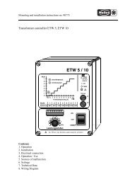
Picture Abb. 3 3<br />
1 Temperature-Pot (Version EH)<br />
2.1 Temperature cut out self resetting<br />
(Version EH)<br />
2.2 Temperature cut out not self resetting<br />
(Version EH)<br />
3 Frost thermostat for <strong>heat</strong> exchanger<br />
4 Condensate outlet<br />
5 Extract pre filter G3<br />
6 Inlet pre filter G3<br />
7 Inlet fine filrter F5<br />
8 Elecrtic <strong>heat</strong>er (Version EH)<br />
9 Supply fan<br />
10 Extract fan<br />
11 Heat exchanger<br />
12 Terminal box<br />
13 Operation switch<br />
14 Door<br />
15 Cover plate extract air<br />
16 Cover plate supply air<br />
17 Temperature sensor supply air<br />
18 Warm water <strong>heat</strong>er battery (Version WW)<br />
19 Flow & return pipes for the warm water(Version WW)<br />
20 Temperature sensor for frost protection ofthe water<br />
<strong>heat</strong>er battery (Version WW)<br />
Parts identification<br />
Input air outside air<br />
extract air extract air<br />
Duct connections<br />
Room side Outside<br />
Input air<br />
extract air outside air<br />
extract air<br />
Picture Abb. 4 4<br />
Hole 7mm dia for DDS<br />
12 mm pipe connections for<br />
the warm water coil<br />
(WW version only)<br />
Input air<br />
extract air<br />
outside air<br />
extract air<br />
Connection hole for DDS<br />
7mm dia hole for DDS<br />
Hole for operation<br />
switch cable<br />
Input air<br />
extract air<br />
outside air<br />
extract air<br />
Condensate outlet 15mm
!<br />
<strong>Central</strong> <strong>ventilation</strong> <strong>with</strong> <strong>heat</strong> <strong>recovery</strong> <strong>unit</strong> <strong>KWL</strong> <strong>250</strong><br />
Operation and installation instructions no. 91581<br />
Picture Abb. 5 5<br />
<strong>KWL</strong><br />
<strong>250</strong> EH<br />
SS-762<br />
Klemmenadapter<br />
Terminalblock<br />
-orange<br />
-blue<br />
-green<br />
-brown<br />
-yellow<br />
-red<br />
-white<br />
-black<br />
or<br />
bl<br />
gn<br />
br<br />
ge<br />
rt<br />
ws<br />
sw<br />
123 4 5 6 7 8<br />
/optional<br />
wahlweise<br />
8 x 0,25 mm² max. 50m<br />
or<br />
bl<br />
gn<br />
br<br />
ge<br />
rt<br />
ws<br />
sw<br />
Datenleitung mit RJ45-Stecker (Adern "gedreht")<br />
Dataline <strong>with</strong> RJ45 plug (wires rotated)<br />
1<br />
2<br />
3<br />
4<br />
5<br />
6<br />
7<br />
8<br />
Steuerplatine Heizung / Heater element<br />
Betriebsschalter<br />
Circuit board<br />
for/ bei <strong>KWL</strong> <strong>250</strong> optional:<br />
Main switch<br />
EHM <strong>250</strong><br />
MIN<br />
NORMAL<br />
MAX<br />
/ Ref.no.<br />
Standardeinstellung,<br />
siehe Montageanleitung<br />
°C<br />
Best.Nr.<br />
0853<br />
for/ bei<br />
<strong>KWL</strong> <strong>250</strong> WW<br />
bei<br />
<strong>KWL</strong> <strong>250</strong> EH<br />
for/<br />
2 3 4 5 6<br />
1<br />
N<br />
on<br />
off<br />
/ incl.<br />
PWW inkl.<br />
/ incl.<br />
inkl.<br />
<strong>KWL</strong>-WSU Best.Nr. 0856<br />
Wochenzeitschaltuhr<br />
Nachtabsenkung,<br />
optional<br />
88<br />
88<br />
Frostschutzthermostat<br />
Warmwasser<br />
potentialfrei<br />
L<br />
For switch settings<br />
see operation and<br />
maintenance manual<br />
Frost protection thermostat warm water<br />
Volt free contact from thermostat<br />
FI<br />
Weekly timer, night set back<br />
(lowers temperature at night)<br />
optional<br />
<strong>KWL</strong> <strong>250</strong><br />
/ Mains supply<br />
Netzstecker<br />
Externes<br />
Temperaturmodul,<br />
optional<br />
External temperature module<br />
optional<br />
15<br />
20<br />
10<br />
PE<br />
N<br />
L1<br />
P<br />
P<br />
/Ref.no.<br />
25<br />
5<br />
2<br />
1<br />
DDS<br />
Best.Nr.<br />
0445<br />
Drucksensor<br />
°C<br />
Trennschalter / On/off switch<br />
optional, VDE 0700 T1 7.12.2<br />
/Differential<br />
pressure switch<br />
optional<br />
92818 002 SS-762 04.02.04
<strong>Central</strong> <strong>ventilation</strong> <strong>with</strong> <strong>heat</strong> <strong>recovery</strong> <strong>unit</strong> <strong>KWL</strong> <strong>250</strong><br />
Operation and installation instructions no.<br />
Druckschrift-Nr. 91581/ 09.03<br />
Service und Information<br />
D <strong>HELIOS</strong> Ventilatoren GmbH & Co · Lupfenstraße 8 · 78056 VS-Schwenningen F <strong>HELIOS</strong> Ventilateurs · Z.I. La Fosse à la Barbière · 2, rue Louis Saillant · 93605 Aulnay sous Bois Cedex<br />
CH <strong>HELIOS</strong> Ventilatoren AG · Steinackerstraße 36 · 8902 Urdorf / Zürich GB <strong>HELIOS</strong> Ventilation Systems Ltd. · 5 Crown Gate · Wyncolls Road · Severalls Industrial Park ·<br />
A <strong>HELIOS</strong> Ventilatoren · Postfach 854 · Siemensstraße 15 · 6023 Innsbruck Colchester · Essex · CO4 9HZ