Download - Herion Systemtechnik GmbH
Download - Herion Systemtechnik GmbH
Download - Herion Systemtechnik GmbH

You also want an ePaper? Increase the reach of your titles
YUMPU automatically turns print PDFs into web optimized ePapers that Google loves.
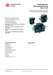
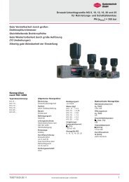
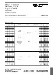
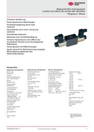
Directional control Valve<br />
size 16<br />
Pilot and directly operated<br />
Spool type valve<br />
Interface acc. to DIN 24340 and ISO 4401<br />
PN [p max. ] = 315 bar 7500901.06.12.08<br />
Description (Standard Appliances)<br />
Design<br />
The S 16 type valves are spool type valves available in<br />
4/2- and 4/3-way designs. The valves can be used as<br />
2- or 3-way designs by closing the appropriate ports.<br />
Actuation<br />
Pilot operated valves are preferably operated by<br />
solenoids. The auxiliary manual operation is only effective<br />
when control pressure is available. Directly operated<br />
versions are available for hydraulic and pneumatic<br />
operation.<br />
Mounting<br />
The units are bolted on subplates and sealed by<br />
O-rings.<br />
Line connector<br />
Subplate, interface to DIN 24340-A16 and<br />
ISO 4401-AD-07-4-A<br />
Characteristics<br />
• damped; facilitates smooth shifting partially throttled<br />
ensures smooth change over<br />
• low volume design<br />
• high power density<br />
• electrical, pneumatic and hydraulic operation<br />
Type key<br />
Directional valve<br />
S 16 ... ... ... G ... ... ... ... ...<br />
1 2 3 4 5 6 7 8<br />
1 Actuation: VH – DC-type solenoid,<br />
pressure-tight, with manual<br />
override<br />
Y – Hydraulic<br />
2 Control type<br />
Pilot Control oil- Control oil Timed<br />
inlet X outlet Y settings<br />
17- S 6 internal external none<br />
18- S 6 external external none<br />
19- S 6 internal external available<br />
20- S 6 external external available<br />
21- S 6 internal internal none<br />
22- S 6 external internal none<br />
23- S 6 internal internal available<br />
24- S 6 external internal available<br />
28- - external external 1) none<br />
29- - external external 1) available<br />
3 Electrical connection: For<br />
operation<br />
00 - Operation without<br />
electrical connection<br />
10 - PG 11 socket according VH<br />
to DIN 43650 mounted<br />
on solenoid<br />
11 - PG 11 socket according VH<br />
to DIN 43650 mounted<br />
on solenoid with integrated<br />
rectifier<br />
13 - PG11 socket according VH<br />
to DIN 43650 mounted<br />
on solenoid, signal indicator<br />
mounted on socket<br />
with timed settings: double-throttle non-return valve is<br />
available for hydraulic directly operated valves as an<br />
intermediate plate<br />
1)<br />
Y = control oil supply<br />
HERION <strong>Systemtechnik</strong> <strong>GmbH</strong><br />
Untere Talstraße 65<br />
D-71263 Weil der Stadt (Merklingen)<br />
Tel.: +49 (0) 70 33/30 18-0<br />
Fax: +49 (0) 70 33/30 18-10<br />
www.herion-systemtechnik.de<br />
info@herion-systemtechnik.de
Type key<br />
4 Symbols:<br />
Symbol No. Symbol<br />
Overlap<br />
020 +<br />
005 +<br />
5 Armature: 001 – Standard configuration<br />
6 Engineering version: 5 – with improved flow<br />
performance<br />
(spheroidal iron)<br />
7 Additional data: O – Standard configuration<br />
M – mechanical detend of the<br />
pilot valve<br />
R – Pilot cartridge in port P 2)<br />
(main valve)<br />
8 Seal material: O – Perbunan<br />
V – Viton<br />
019 1) +<br />
008 +<br />
009 +<br />
011 2) -<br />
Subplate<br />
P S 16 G ... 001 ... O O<br />
1 2<br />
1 Line connector: 5 – G 3/4 (Internal thread<br />
6 – G 1 according to<br />
DIN ISO 228/1)<br />
2 Engineering Revision: 2<br />
013 2) -<br />
For the symbols shown: Solenoid operated valve with<br />
control pattern 17<br />
1) Locking not possible with hydraulic and direct<br />
pneumatic operation.<br />
2) Control patterns 17, 19, 21 and 23 are only possible<br />
in conjunction with symbols 011 and 013 with a precharge<br />
cartridge valve in P.<br />
2 Design subject to change without notice<br />
7500901.06.12.08
Parameter to VDI 3267<br />
Type designation S 16 VH S 16 Y<br />
General parameters<br />
Designation<br />
Directional control valve<br />
Type<br />
Spool-type valve<br />
Symbol<br />
See type key<br />
Mounting type<br />
Flange<br />
Line connector<br />
Subplate<br />
Weight of valve<br />
[kg]<br />
1 actuator 9.7<br />
2 actuators 10,3<br />
Weight of subplate [kg]<br />
G 3/4 9.0<br />
G 1 9.0<br />
Weight ofdouble-throttle<br />
non-return valve [kg] 1.7<br />
Mounting position<br />
any<br />
Ambient temperature<br />
range ϑ u [°C] –20 to +50<br />
Nominal size 16<br />
Type description S 16 VH S 16 Y<br />
Hydraulic parameters<br />
Operating pressure<br />
range p [bar]<br />
X = extern 315<br />
Port P, A, B: X = intern 315 -<br />
Port T: X = extern 315<br />
Y = intern 160 -<br />
Control pressure 1) 8.5 1) 8.5<br />
to to<br />
p St [bar] 2) 315 315<br />
Control volume V St [cm 3 ]<br />
Symbol<br />
019, 020 8.4<br />
005, 008,<br />
009, 011 4.2<br />
013 4.9<br />
Temperature of<br />
max.<br />
pressure medium ϑ m [°C] +70<br />
Viscosity<br />
range ν [mm 2 /s] 12 to 500<br />
Flow valume Q [l/min] see characeristic<br />
curves<br />
1) V St min 10 bar for symbol 013<br />
2) For symbols 011 and 013 the control pressure is<br />
achieved by the precharge cartridge valve in P.<br />
Electrical parameters<br />
Operation<br />
VH<br />
Switching time 3) t e [ms] 50<br />
(pilot valve) t a [ms] 30<br />
No. of switchings/h approx. 15 000<br />
Rated voltage VU N [V] Standard voltages<br />
Connector input DC 24 AC 230 V<br />
40 ... 60 HZ<br />
± 10% + 5%/-10 %<br />
Special voltages on<br />
request<br />
Operation<br />
VH<br />
Current P 20 [W] 27<br />
draw<br />
P 20 [VA] ∼ -<br />
Duty cycle ED rel [%] 100<br />
Degree of protectionfor solenoid<br />
and elictrical connection to<br />
DIN 40 050 IP 65<br />
Electrical connection:<br />
see Type keys<br />
3) The main valve switching time is dependant on the<br />
control oil supply.<br />
Characteristic curves<br />
Pilot cartridge in P<br />
For all symbols apart from 013<br />
Symbol<br />
7500901.06.12.08 Design subject to change without notice<br />
3
Control modes<br />
Control type: 17<br />
detailed symbol<br />
simple symbol<br />
Internal control oil feed:<br />
Port “X“ in subplate closed.<br />
Port “p“ in main valve opened.<br />
External control oil feed:<br />
Connector for control oil return in “Y“ in subplate.<br />
Port “t“ in main valve closed.<br />
4/2-<br />
Control<br />
valve<br />
020<br />
4/2-<br />
Control<br />
valve<br />
019<br />
4/2-<br />
Control<br />
valve<br />
008<br />
Control type: 18<br />
External control oil feed:<br />
Connector for control oil in “X“ in subplate.<br />
Port “p“ in main valve closed.<br />
4/3-<br />
Control<br />
valve<br />
008<br />
External control oil return:<br />
Connector for control oil return in “Y“ in subplate.<br />
Port “t“ in main valve closed.<br />
Control type: 19<br />
Switching time settings:<br />
The switching times of the main valve can be<br />
influenced by a double throttle non-return valve,<br />
which throttles the control oil supply.<br />
4/3-<br />
Control<br />
valve<br />
008<br />
The switching times are changed with the following<br />
settings:<br />
Throttle 1: from 0 to a<br />
from b to 0<br />
Throttle 2: from 0 to b<br />
from a to 0<br />
Internal control oil flow<br />
External control oil return<br />
Control type: 28<br />
Direct hydraulic operation.<br />
Control oil feed “X“ and “Y“ in the subplate.<br />
4/2-<br />
Control<br />
valve<br />
020<br />
4 Design subject to change without notice<br />
7500901.06.12.08
Ordering<br />
The units are designated by their type number. The<br />
composition of this number can be drawn from the type<br />
code. The standard versions are listed in the type<br />
survey. When ordering any of the standard versions,<br />
please state type number as well as catalog number to<br />
preclude possible misinterpretations.<br />
When inquiring about ordering units not listed in our<br />
type survey of thid publication, the type number by you<br />
by means of the type code, however, will do. The<br />
corresponding catalog number will be than stated in our<br />
confirmation order.<br />
Flange valves are provided with O-rings. Subplate and<br />
mounting screws must be ordered seperately.<br />
Example of order<br />
4/3-way NG 16 directional valve, pilot operated;<br />
AC 230V 50 Hz, Electrical connection: Connector with<br />
rectifier on solenoid, symbol 008, internal control oil flow,<br />
external control oil return, with G 3/4" subplate.<br />
Directional control valve:<br />
Type description S 16 VH 17 11 G 008 001 5 O O<br />
Order No.: 5202399.7234 205 O O<br />
4/3-way NG 16 directional valve, pilot opersted;<br />
DC 24V; Electrical connection: Connector with rectifier on<br />
solenoid, symbol 008, internal control oil flow, external<br />
control oil return, with G 3/4" subplate.<br />
Directional control valve:<br />
Type description S 16 VH 17 10 G 008 001 5 O O<br />
Order no.: 5202388.7234<br />
Voltage:<br />
24 V<br />
Mounting plate:<br />
Type description P S 16 G 5 001 2 O O<br />
Order no.: 1065186<br />
Type survey (standard versions)<br />
1) Simplified main<br />
and pilot valve<br />
symbol<br />
Symbol No<br />
Overlap<br />
Control mode<br />
Actation<br />
Electrical<br />
connection<br />
Line<br />
connection<br />
Voltage<br />
Type<br />
Cat No.<br />
Valve<br />
Solenoid<br />
020 +<br />
019 +<br />
008 +<br />
009 +<br />
013 -<br />
17<br />
19<br />
17<br />
19<br />
17<br />
19<br />
17<br />
19<br />
17<br />
19<br />
Pilot valve: solenoid operation; pressure sealed main valve: hydraulic<br />
No. 10: PG 11 socket according to DIN 43650 mounted on solenoid<br />
Subplate: G 3/4" type: P S 16 G 5 001 2 O O order no. 1065186<br />
G 1” type: P S 16 G 6 001 2 O O order no. 1065187<br />
∼<br />
∼<br />
∼<br />
∼<br />
∼<br />
∼<br />
∼<br />
∼<br />
∼<br />
∼<br />
S 16 VH 17 10 G 020 001 5 O O<br />
S 16 VH 17 11 G 020 001 5 O O<br />
S 16 VH 19 10 G 020 001 5 O O<br />
S 16 VH 19 11 G 020 001 5 O O<br />
S 16 VH 17 10 G 019 001 5 M O<br />
S 16 VH 17 11 G 019 001 5 M O<br />
S 16 VH 19 10 G 019 001 5 M O<br />
S 16 VH 19 11 G 019 001 5 M O<br />
S 16 VH 17 10 G 008 001 5 O O<br />
S 16 VH 17 11 G 008 001 5 O O<br />
S 16 VH 19 10 G 008 001 5 O O<br />
S 16 VH 19 11 G 008 001 5 O O<br />
S 16 VH 17 10 G 009 001 5 O O<br />
S 16 VH 17 11 G 009 001 5 O O<br />
S 16 VH 19 10 G 009 001 5 O O<br />
S 16 VH 19 11 G 009 001 5 O O<br />
S 16 VH 17 10 G 013 001 5 R O<br />
S 16 VH 17 11 G 013 001 5 R O<br />
S 16 VH 19 10 G 013 001 5 R O<br />
S 16 VH 19 11 G 013 001 5 R O<br />
5203427.7234<br />
5203428.7234<br />
5203429.7234<br />
5203430.7234<br />
5203104.7234<br />
5204044.7234<br />
5203432.7234<br />
5204045.7234<br />
5202388.7234<br />
5202399.7234<br />
5202393.7234<br />
5202404.7234<br />
5202389.7234<br />
5202400.7234<br />
5202394.7234<br />
5202405.7234<br />
5202390.7234<br />
5202401.7234<br />
5202395.7234<br />
5202406.7234<br />
1) Symbols are shown in operation type 17 - electro-hydraulic<br />
with control type: 17<br />
7500901.06.12.08 Design subject to change without notice<br />
5
Dimensional Drawings<br />
Directional valve: See subplate dimensioned drawing for the dimensions of the connection layout.<br />
Interface S16<br />
DIN 24340 - A 16 / ISO 4401<br />
Tightening torque:<br />
M 15 DIN 912 - 10.9 = 17.6 Nm<br />
M 15 DIN 912 - 10.9 = 13 Nm<br />
M 10 DIN 912 - 10.9 = 62 NM<br />
El. connection<br />
11 and 13<br />
Solenoid can<br />
be rotated 90 o<br />
M 5<br />
Pilot valve<br />
S6 VH...<br />
∼190 AC version<br />
∼1188 DC version<br />
M6<br />
M10<br />
Main valve<br />
S16<br />
Section C-D<br />
Section A-B<br />
Screw not required for<br />
“internal control oil<br />
return“ version<br />
Screw not required for<br />
“internal control oil feed“<br />
version<br />
Pilot valve in connection P<br />
(depends on symbol and control type)<br />
6 Design subject to change without notice<br />
7500901.06.12.08
Dimensional Drawings<br />
Direct hydraulic<br />
operated<br />
S 16 Y 28 00 G ...<br />
Switching times set<br />
by double throttle<br />
non-return valve<br />
MU 2 S6 ...<br />
Control type<br />
19, 20, 23, 24, 29<br />
El. connection<br />
11 and 13<br />
M 5x70 DIN 912 - 10.9<br />
Tightening torque = 7.7 Nm<br />
∼228 DC version<br />
7500901.06.12.08 Design subject to change without notice<br />
7
Dimensional Drawings<br />
Subplate with port arrangement according to DIN 24340-A 16 and ISO 4401-AD-07-4-A<br />
Cut-out for<br />
connections in<br />
control face<br />
8 depth<br />
Section A-B<br />
Connection “L“ is only<br />
required for valves with<br />
switching speed<br />
monitoring which are<br />
available on request.<br />
Order no.:<br />
10 651 86<br />
10 651 81<br />
a<br />
G 3/4<br />
G 1<br />
b<br />
ø 41<br />
ø 47<br />
c<br />
16,5<br />
18,5<br />
8 Design subject to change without notice<br />
7500901.06.12.08
Spare Part Drawings<br />
Pilot valve<br />
S 6...<br />
Part section A-B<br />
Part section C-D<br />
Main valve<br />
S 16...<br />
Subplate<br />
Screw not required for “external control oil feed“ version<br />
M 5x70 DIN 912 - 10.9<br />
Tightening torque = 7.6 Nm<br />
El. – connection<br />
11 and 13<br />
Pilot valve<br />
Double throttle<br />
non-return valve<br />
MU 2 S6 ...<br />
Throttle 1<br />
Throttle 2<br />
Main valve<br />
7500901.06.12.08 Design subject to change without notice<br />
9
Spare Part Drawings<br />
Direct hydraulic operatied<br />
Piston position for spring operation<br />
and for spare parts in relationship to<br />
symbols 019 and 012 (compression<br />
spring is not required with symbol<br />
019).<br />
005<br />
008, 009, 011, 012, 013<br />
10 Design subject to change without notice<br />
7500901.06.12.08
Individual Spare Parts<br />
Part<br />
1<br />
2<br />
3<br />
4<br />
5<br />
6<br />
7<br />
8<br />
9<br />
10<br />
10<br />
11<br />
11<br />
12<br />
Description<br />
O-ring (22.4 x 2.5)<br />
O-ring (10 x 2)<br />
O-ring (33 x 2.6)<br />
O-ring (7.7 x 1.8)<br />
Compression spring<br />
Plug screw<br />
Plug screw<br />
Plug screw<br />
Plug screw<br />
1) Pilot valve complete<br />
O-ring (9.2 x 1.8)<br />
Double throttle non-return valve complete<br />
Connecting valve plate complete<br />
O-ring (9.2 x 1.8)<br />
S 16 VH ...<br />
S 16 ...<br />
4<br />
2<br />
2<br />
2<br />
1<br />
1<br />
1<br />
1<br />
1<br />
-<br />
-<br />
-<br />
-<br />
S 16 VH ...<br />
S 16 ...<br />
with double<br />
throttle<br />
non-return valve<br />
4<br />
2<br />
2<br />
2<br />
S 16 Y 2800<br />
see “Piston stroke for spring operation“ spare part diagram<br />
1<br />
1<br />
1<br />
1<br />
1<br />
-<br />
1<br />
-<br />
4<br />
4<br />
2<br />
2<br />
2<br />
1<br />
1<br />
-<br />
-<br />
-<br />
4<br />
-<br />
1<br />
-<br />
(PC B)<br />
(AC T)<br />
Order no.:<br />
0662256<br />
0659116<br />
0701300<br />
0701251<br />
-<br />
0700514<br />
0700514<br />
0701222<br />
0701222<br />
-<br />
0701252<br />
5400060<br />
2840093<br />
0701252<br />
Mounting screws<br />
-<br />
-<br />
Socket head screws<br />
(M6 x 55 DIN 912-10.9)<br />
Socket head screws<br />
(M10 x 60 DIN 912-10.9)<br />
2 2 2 0700415<br />
4 4 4 0700457<br />
1 Set of replacement wearing parts consists<br />
of the following:<br />
1 to 4 1 to 4,<br />
12 and 13<br />
1 to 4<br />
and 10<br />
-<br />
1) Pilot valve complete For 2-position valves with spring = 1 off or S 6 VH 10 G 020 001 1 O V<br />
return 1 off S 6 SH 10 G 020 001 1 O V<br />
For 2-position valves with = 1 off or S 6 VH 10 G 019 001 1 M V<br />
ocking 1 off S 6 VH 11 G 019 001 1 M V<br />
For 3-position valves with spring = 1 off or S 6 VH 10 G 009 001 1 O V<br />
return to central 0 position 1 off S 6 SH 10 G 009 001 1 O V<br />
+ Voltage<br />
+ Voltage<br />
+ Voltage<br />
See 7501292 for spare parts for NG 6 pilot valve.<br />
7500901.06.12.08 Design subject to change without notice<br />
11