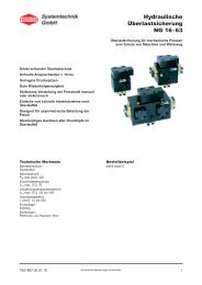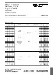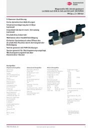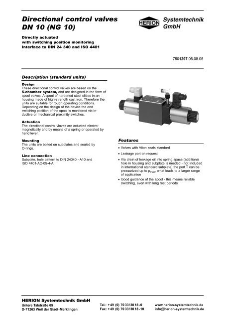
Directional control valves DN 10 - Herion Systemtechnik GmbH
Directional control valves DN 10 - Herion Systemtechnik GmbH
Directional control valves DN 10 - Herion Systemtechnik GmbH

You also want an ePaper? Increase the reach of your titles
YUMPU automatically turns print PDFs into web optimized ePapers that Google loves.
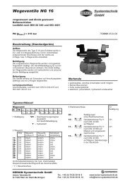
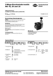
<strong>Directional</strong> <strong>control</strong> <strong>valves</strong><br />
<strong>DN</strong> <strong>10</strong> (NG <strong>10</strong>)<br />
Directly actuated<br />
with switching position monitoring<br />
Interface to DIN 24 340 and ISO 4401<br />
7501297.06.08.05<br />
Description (standard units)<br />
Design<br />
These directional <strong>control</strong> <strong>valves</strong> are based on the<br />
5-chamber system, and are designed in the form of<br />
spool <strong>valves</strong>. A spool of hardened steel slides in an<br />
housing made of high-strength cast iron. Therefore the<br />
units are suitable for rough operating conditions.<br />
Depending on the design of the device the end<br />
switching position of the spool is monitored via inductive<br />
or mechanical proximity switches.<br />
Actuation<br />
The directional <strong>control</strong> vlaves are actuated electromagnetically<br />
and by means of a spring or operated by<br />
hand lever.<br />
Mounting<br />
The units are bolted on subplates and sealed by<br />
O-rings.<br />
Line connection<br />
Subplate, hole pattern to DIN 24340 - A<strong>10</strong> and<br />
ISO 4401-AC-05-4-A.<br />
Features<br />
• Valves with Viton seals standard<br />
• Leakage port on request<br />
• Via drain of leakage oil into spring space (additional<br />
hole in housing and subplate is needed - not included<br />
in international standard subplate) the port T can be<br />
pressurized up to p max , what leads to a larger range<br />
of application<br />
• Good guidance of the spool - this means reliable<br />
switching, even with long rest periods<br />
HERION <strong>Systemtechnik</strong> <strong>GmbH</strong><br />
Untere Talstraße 65<br />
D-71263 Weil der Stadt-Merklingen<br />
Tel.: +49 (0) 70 33/30 18-0<br />
Fax: +49 (0) 70 33/30 18-<strong>10</strong><br />
www.herion-systemtechnik.de<br />
info@herion-systemtechnik.de
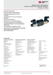
Type code<br />
<strong>Directional</strong> <strong>control</strong> valve<br />
S <strong>10</strong> ... ... G ... ... ... ... ...<br />
1 2 3 4 5 6 7<br />
1 Actuation: G – DC solenoid<br />
(with dry operation system)<br />
with manual override<br />
B – DC solenoid<br />
(with dry operation system)<br />
without manual override<br />
V – DC solenoid, pressuretight<br />
without manual override<br />
VH – DC solenoid, pressuretight<br />
with manual override<br />
H – manually operated<br />
2 Electrical connection:<br />
Code<br />
Actuation Number Symbol<br />
Description<br />
G, B <strong>10</strong> Connector Pg 11<br />
to DIN 43 650<br />
on solenoid<br />
124<br />
G, B 56 Connector<br />
(Tuchel) at<br />
connection box<br />
171<br />
3 Symbol: 020 – See type survey<br />
4 Code: Mechanical end switch<br />
039 – Position monitoring of<br />
switching position directly<br />
at spool, 1 end switch.<br />
Electrical connection:<br />
Tuchel-connector<br />
061 – Position monitoring of 3<br />
switching positions at the<br />
solenoid, 3 end switches.<br />
Electrical connection:<br />
Harting-connector R 15<br />
066 – Position monitoring of 2<br />
switching positions at the<br />
solenoid, 2 end switches.<br />
Electrical connection:<br />
Tuchel-connector<br />
4 Code: Inductive proximity<br />
switches<br />
221 – Position monitoring of 1<br />
switching position<br />
switch at side b C spool<br />
position b damped<br />
switch at side a C spool<br />
position a damped<br />
with 4/3-directional <strong>control</strong><br />
<strong>valves</strong> spool position 0<br />
damped<br />
222 – Position monitoring of 2<br />
switching positions<br />
1 switch at side a<br />
spool position a damped<br />
1 switch at side b<br />
spool position b damped<br />
224 – Position monitoring of<br />
1 switching position<br />
(2 switches) spool position<br />
0 damped<br />
225 – Position monitoring of<br />
1 switching position<br />
1 switch at side b<br />
spool position a damped<br />
5 Engineering version:5<br />
6 Additional data: O – Standard design<br />
M – Mechanical detent<br />
7 Sealing material: V – FKM (e.g. Viton)<br />
Subplate<br />
P S <strong>10</strong> G ... ... ... ... O O<br />
1 2 3<br />
1 Line connection: 4 – G 1/2 (Internal thread<br />
5 – G 3/4 to DIN ISO 228/1)<br />
2 Code: 001 – Standard design<br />
3 Engineering<br />
version: 2<br />
Parameters according to VDI 3267<br />
Type designation G B VH V<br />
General parameters<br />
Designation<br />
<strong>Directional</strong> <strong>control</strong> valve<br />
Symbol<br />
See type survey<br />
Design<br />
Spool-type valve<br />
Type of mounting<br />
Flange<br />
Line connection<br />
Subplate<br />
Mounting position<br />
Preferably horizontal<br />
Weight 1 actuator [kg] 7,2 6,5<br />
2 actuators 8,8 7,3<br />
Weight of subplate G 1/2 [kg] 2<br />
G 3/4 2,7<br />
Ambient temperature range ϑ u [°C] –20 to +50<br />
Size <strong>DN</strong> <strong>10</strong><br />
2 Subject to alteration<br />
7501297.06.08.05
Type designation G B VH V<br />
Hydraulic parameters<br />
Operating pressure range p e max. [bar]<br />
at port P, A, B ... 315<br />
at port T (without leakage port) ... <strong>10</strong>0 ... 50 2)<br />
at port T (with leakage port) ... 315 1) –<br />
Pressure fluid temperature ϑ m max. [°C] +70<br />
Viscosity range ν [mm 2 /s] 12 ... 500<br />
Flow Q max (l/min) See characteristic curve<br />
Filtration Oil purity class to ISO 4406: 18/15<br />
Other parameters<br />
1) on request; 2) > 50 bar on request<br />
PIN assignment for Tuchel-connection:<br />
Valve with 1 solenoid Solenoid ”a“ at 1 and 2 or –<br />
Solenoid ”b“ at 3 and 4<br />
Ground wire at<br />
Valve with 2 solenoids Solenoid ”a“ at 1 and 2 –<br />
Solenoid ”b“ at 3 and 4<br />
Ground wire at<br />
Switching times t approx. [ms]<br />
(measured at 315 bar, t on 70 ... 95 1)<br />
60 l/min) t off 70 ... 80 1)<br />
Approx. number of switchings/h 15.000 (3600 for symbol 039)<br />
Rated voltage U N [V] DC 24 ± <strong>10</strong> % (Other voltages available on request)<br />
Power consumption P 20 [W] 36 42<br />
Duty cycle ED rel [%] <strong>10</strong>0<br />
Degree of protection for solenoid and<br />
electrical connection to DIN 40 050 IP 54 IP 65<br />
Maunal override yes no yes no<br />
Characteristic curves: flow curves: ?p = f(Q)<br />
Power limits Q max:<br />
Flow direction<br />
Symbol<br />
Characteristic curve<br />
Symbol<br />
001<br />
003<br />
008, 004, 094<br />
013<br />
017<br />
019<br />
020, 039<br />
177<br />
P-A P-B A-T B-T P-T<br />
6<br />
1<br />
1<br />
3<br />
-<br />
1<br />
1<br />
1<br />
6<br />
1<br />
1<br />
3<br />
6<br />
1<br />
1<br />
1<br />
-<br />
3<br />
5<br />
2<br />
2<br />
3<br />
3<br />
3<br />
-<br />
3<br />
5<br />
7<br />
-<br />
3<br />
3<br />
-<br />
-<br />
-<br />
-<br />
8<br />
8<br />
-<br />
-<br />
-<br />
001, 117<br />
003<br />
008, 004, 094, 017, 019<br />
013, 020, 039<br />
2<br />
4<br />
1<br />
5<br />
7501297.06.08.05 Subject to alteration<br />
3
Electrical parameters and pin-plan (inductive proximity switches)<br />
Code 039<br />
Precision switch according to DIN 43 695<br />
Isolation Group ”C“ according to VDE 01<strong>10</strong><br />
Nominal voltage ~[V] 250<br />
Continuous current ~[A] 6<br />
Contact system<br />
Dual-circuit directional contact with 2 galvanical and thermical separated contact bridges<br />
Switching system<br />
Snap system with friction contacts<br />
Switching force [N] max. 4,4<br />
Reset force [N] min. 1,3<br />
Duration of bounce (at <strong>10</strong> mm/min contact velocity) [ms] ≤ 1,5<br />
Circuit time (at <strong>10</strong> mm/min contact velocity) [ms] ≤ <strong>10</strong><br />
Number of switching max. switching/min 300<br />
mechanical at 1,6 switchings/s > 50 million switching cycles (VDE 0660 E3)<br />
electrical<br />
dependance on load cycles/min<br />
Reproduceability of switching point [µm] ± 2<br />
Allowable ambient temperature t [°C] – 30 ... + 90<br />
Contact material<br />
Fine silver, system gold plated<br />
Contact arrangement normally closed contact 1 + 2<br />
normally open contact 3 + 4<br />
Dimensional drawing<br />
Pin plan (switch with Tuchel connector)<br />
Code 061 und 066<br />
Micro switch (mechanical end switch<br />
according to DIN 41 635)<br />
Type<br />
<strong>Directional</strong> contact<br />
VCS<br />
Reset force [N] max. 1,1<br />
Switching force [N] max. 3,3<br />
single line<br />
Allowable ambient temperature t [°C] – 20 ... + 85<br />
Dimensional drawing<br />
Switching performance<br />
DC === AC ~<br />
Resistive 24 V 6 A Resistive 125 V <strong>10</strong> A<br />
load 125 V 0,5 A load 250 V <strong>10</strong> A<br />
250 V 0,25 A<br />
Inductive 24 V 6 A Inductive 25 V 6 A<br />
load 125 V 0,07 A load 125 V 0,07 A<br />
250 V 0,03 A 250 V 0,03 A<br />
1 = common<br />
2 = normally closed<br />
3 = normally open<br />
Pin plan (switch with Harting-connector R15)<br />
Code 061<br />
Valve with 3 switching positions<br />
Pin plan (switch with Tuchel-connector)<br />
Code 066<br />
Valve with 2 switching positions<br />
4 Subject to alteration<br />
7501297.06.08.05
Electrical parameters and pin-plan (inductive proximity switches)<br />
Code 221, 222, 224, 225<br />
Inductive proximity switch (pressure tight)<br />
Inductive proximity switch M 12 x 1<br />
PNP-normally opened<br />
Rated voltage U e [V] DC 24<br />
Normal voltage U B [V] DC <strong>10</strong> to 30<br />
Voltage drop U D at I e [V] ≤ 1,5<br />
Rated current I e [mA] 200<br />
Safety against reverse polarity<br />
yes<br />
Short circuit proof<br />
yes / yes<br />
Allowable load [µF] ≤ 1,0<br />
Protection class according to IEC 529 IP 68 according to BWN Pr. 20<br />
(IP 67 plug compl.)<br />
Type of connection Connector M 12 x 1<br />
Pressure-tight up to [bar] 50 at active face<br />
Circuit diagram<br />
brown<br />
black<br />
blue<br />
Pin assignment end switch<br />
Attention! Switches will be adjusted before delivery.<br />
Female connector M 12 x 1 incl. beard with LED<br />
Pin assignment connector<br />
Type<br />
angled connector 4 line<br />
Wire pull relief<br />
Pg 7 for wire ø 4 to 6 mm<br />
Protection class IP 67<br />
LED-Indication yes (2)<br />
– Power on green<br />
– Function yellow<br />
Type survey (standard)<br />
Code 039<br />
Symbol 1)<br />
Code 061<br />
Symbol-No.<br />
Overlap<br />
Actuation<br />
001 5) + 01<br />
003<br />
020<br />
+<br />
+<br />
Solenoid-actuated,<br />
dry op. system<br />
Dimensional<br />
drawing<br />
Spare part<br />
drawing<br />
01<br />
01<br />
01<br />
01<br />
01<br />
Electrical<br />
connection<br />
(Solenoid)<br />
No. <strong>10</strong><br />
Connector<br />
(Pg 11)<br />
to DIN<br />
43 650<br />
on solenoid<br />
Line connection Type Cat. No.<br />
Subplate G 1/2<br />
P S <strong>10</strong> G 4 001 2 O O<br />
Cat. No.<br />
<strong>10</strong>65184<br />
Subplate G 3/4<br />
P S <strong>10</strong> G 5 001 2 O O<br />
Cat. No.<br />
<strong>10</strong>65185<br />
Voltage<br />
VDC<br />
VDC<br />
VDC<br />
VDC<br />
S <strong>10</strong> G <strong>10</strong> G 001 039 5 OV<br />
S <strong>10</strong> G <strong>10</strong> G 003 039 5 OV<br />
S <strong>10</strong> G <strong>10</strong> G 020 039 5 OV<br />
S <strong>10</strong> B <strong>10</strong> G 020 039 5 OV<br />
Valve<br />
Solenoid<br />
5205219.7623<br />
5205236.7623<br />
5205118.7623<br />
52052<strong>10</strong>.7624<br />
008 + 02<br />
009<br />
013<br />
+<br />
-<br />
Solenoid-actuated,<br />
dry op. system<br />
02<br />
02<br />
02<br />
02<br />
02<br />
No. 56<br />
Connector<br />
(Tuchel) at<br />
connection<br />
box<br />
Subplate G 1/2<br />
P S <strong>10</strong> G 4 001 2 O O<br />
Cat. No.<br />
<strong>10</strong>65184<br />
Subplate G 3/4<br />
P S <strong>10</strong> G 5 001 2 O O<br />
Cat. No.<br />
<strong>10</strong>65185<br />
VDC<br />
VDC<br />
VDC<br />
VDC<br />
S <strong>10</strong> G 56 G 008 061 5 OV<br />
S <strong>10</strong> G 56 G 009 061 5 OV<br />
S <strong>10</strong> G 56 G 013 061 5 OV<br />
S <strong>10</strong> B 56 G 013 061 5 OV<br />
5204988.9000 2)<br />
5204989.9000 2)<br />
5204990.9000 2)<br />
5204991.9000 3)<br />
Code 066<br />
001 5) + 03<br />
003<br />
020<br />
019<br />
-<br />
+<br />
+<br />
Solenoid-actuated, dry op. system<br />
03<br />
03<br />
04<br />
03<br />
03<br />
03<br />
02<br />
No. 56<br />
Connector<br />
(Tuchel) at<br />
connection<br />
box<br />
Subplate G 1/2<br />
P S <strong>10</strong> G 4 001 2 O O<br />
Cat. No.<br />
<strong>10</strong>65184<br />
Subplate G 3/4<br />
P S <strong>10</strong> G 5 001 2 O O<br />
Cat. No.<br />
<strong>10</strong>65185<br />
VDC<br />
VDC<br />
VDC<br />
VDC<br />
S <strong>10</strong> G 56 G 001 066 5 OV<br />
S <strong>10</strong> G 56 G 003 066 5 OV<br />
S <strong>10</strong> G 56 G 020 066 5 OV<br />
S <strong>10</strong> G 56 G 019 066 5 MV<br />
5205<strong>10</strong>1.7639<br />
5205121.7639<br />
5205192.7639<br />
5204987.9000 4)<br />
1) For other symbols, see Publication 7503297<br />
2) Solenoid-Cat.- No. 9000 means: Solenoid a = 7637, Solenoid b = 7601<br />
3) Solenoid-Cat.- No. 9000 means: Solenoid a = 7638, Solenoid b = 7605<br />
4) Solenoid-Cat.- No. 9000 means: Solenoid a = 7639, Solenoid b = 7601<br />
5) Port T of this 3/2 directional <strong>control</strong> <strong>valves</strong> is used as leak oil connection<br />
7501297.06.08.05 Subject to alteration<br />
5
Type survey (standard)<br />
Code-No.<br />
221<br />
Symbol<br />
Symbol-No.<br />
Overlap<br />
Actuation<br />
Dimensional<br />
drawing<br />
Spare part<br />
drawing<br />
001 2) + 05 04<br />
003<br />
020<br />
004<br />
005<br />
039<br />
-<br />
+<br />
+<br />
+<br />
+<br />
Solenoid-actuated, pressure tight<br />
05<br />
05<br />
05<br />
06<br />
06<br />
04<br />
04<br />
04<br />
04<br />
04<br />
Electrical<br />
connection<br />
(Solenoid)<br />
No. <strong>10</strong><br />
Connector<br />
(Pg 11)<br />
to DIN<br />
43650<br />
on solenoid<br />
Line connection Type Cat. No.<br />
Subplate G 1/2<br />
P S <strong>10</strong> G 4 001 2 O O<br />
Cat. No.<br />
<strong>10</strong>65184<br />
Subplate G 3/4<br />
P S <strong>10</strong> G 5 001 2 O O<br />
Cat. No.<br />
<strong>10</strong>65185<br />
Voltage<br />
VDC<br />
VDC<br />
VDC<br />
VDC<br />
VDC<br />
VDC<br />
VDC<br />
Valve<br />
Solenoid<br />
S <strong>10</strong> V <strong>10</strong> G 001 221 5 O V 5205145.7911<br />
S <strong>10</strong> V <strong>10</strong> G 003 221 5 O V<br />
S <strong>10</strong> VH <strong>10</strong> G 003 221 5 O V<br />
S <strong>10</strong> VH <strong>10</strong> G 020 221 5 O V 5205079.7908<br />
S <strong>10</strong> VH <strong>10</strong> G 004 221 5 O V 5205054.7911<br />
S <strong>10</strong> V <strong>10</strong> G 005 221 5 O V<br />
5205080.7911<br />
5205092.7908<br />
5205476.7911<br />
S <strong>10</strong> VH <strong>10</strong> G 039 221 5 O V 5205191.7908<br />
094<br />
+<br />
06<br />
04<br />
VDC<br />
S <strong>10</strong> V <strong>10</strong> G 094 221 5 O V 5205040.7911<br />
166<br />
+<br />
05<br />
04<br />
VDC<br />
S <strong>10</strong> V <strong>10</strong> G 166 221 5 C V<br />
5205070.7911<br />
008<br />
+<br />
07<br />
05<br />
VDC<br />
VDC<br />
S <strong>10</strong> V <strong>10</strong> G 008 221 5 O V<br />
S <strong>10</strong> V <strong>10</strong> G 008 221 5 C V<br />
5205085.7911<br />
5205398.7911<br />
117<br />
+<br />
07<br />
05<br />
VDC<br />
S <strong>10</strong> V <strong>10</strong> G 117 221 5 O V<br />
5205086.7911<br />
138 + 07 05<br />
VDC S <strong>10</strong> V <strong>10</strong> G 138 221 5 O V 5205380.7911<br />
198 + 07 05<br />
VDC S <strong>10</strong> VH <strong>10</strong> G 198 221 5 O V 5205331.7908<br />
241 + 07 05<br />
VDC S <strong>10</strong> V <strong>10</strong> G 241 221 5 O V 5205345.7911<br />
222<br />
019<br />
+<br />
08<br />
06<br />
VDC<br />
S <strong>10</strong> VH <strong>10</strong> G 019 222 5 M V 5205139.7908<br />
013<br />
-<br />
08<br />
06<br />
VDC<br />
VDC<br />
S <strong>10</strong> V <strong>10</strong> G 013 222 5 C V<br />
S <strong>10</strong> V <strong>10</strong> G 013 222 5 O V<br />
5205071.7911<br />
5205346.7911<br />
001 + 08 06<br />
VDC S <strong>10</strong> V <strong>10</strong> G 001 222 5 O V 5205279.7911<br />
008 + 08 06<br />
VDC S <strong>10</strong> V <strong>10</strong> G 008 222 5 O V 5205409.7911<br />
009 + 08 06<br />
VDC S <strong>10</strong> V <strong>10</strong> G 009 222 5 O V 5205311.7911<br />
011 - 08 06<br />
VDC S <strong>10</strong> VH <strong>10</strong> G 011 222 5 O V 5205332.7908<br />
003 - 08 06<br />
VDC S <strong>10</strong> V <strong>10</strong> G 003 222 5 O V 5205315.7911<br />
020 + 08 06<br />
VDC S <strong>10</strong> VH <strong>10</strong> G 020 222 5 O V 5205273.7908<br />
184 - 08 06<br />
VDC S <strong>10</strong> V <strong>10</strong> G 184 222 5 O V 5205340.7911<br />
271 + 08 06<br />
VDC S <strong>10</strong> VH <strong>10</strong> G 271 222 5 O V 5205464.7908<br />
224<br />
013<br />
-<br />
08<br />
06<br />
VDC<br />
S <strong>10</strong> V <strong>10</strong> G 013 224 5 C V<br />
5205185.7911<br />
225<br />
166<br />
+<br />
05<br />
04<br />
VDC<br />
S <strong>10</strong> V <strong>10</strong> G 166 225 5 C V<br />
5205186.7911<br />
019<br />
+<br />
09<br />
07<br />
VDC<br />
S <strong>10</strong> V <strong>10</strong> G 019 225 5 M V 5205090.7911<br />
019<br />
+<br />
manually<br />
operated<br />
<strong>10</strong><br />
09<br />
S <strong>10</strong> H 00 G 019 225 5 M V 5205546.0000<br />
1) For other symbols, see Publication 7503297.<br />
2) Port T of this 3/2 directional <strong>control</strong> <strong>valves</strong> is used as leak oil connection<br />
6 Subject to alteration<br />
7501297.06.08.05
Ordering<br />
The units are designated by their type number. The<br />
composition of this number can be drawn from the type<br />
code. The standard versions are listed in the type<br />
survey. When ordering any of the standard versions,<br />
please state type number as well as catalog number to<br />
preclude possible misinterpretations.<br />
Further valve versions can be composed via combination<br />
of types. The catalog number of these devices<br />
you will get on request.<br />
Flanges <strong>valves</strong> are provided with O-rings and<br />
connector. Subplate and mounting screws must be<br />
ordered separately.<br />
Example of order<br />
Wanted: 4/2 directional <strong>control</strong> valve <strong>DN</strong> <strong>10</strong>, 24 VDC,<br />
connector on solenoid, Symbol 020, along with<br />
corresponding subplate.<br />
<strong>Directional</strong> <strong>control</strong> valve:<br />
Type No.:<br />
S <strong>10</strong> G <strong>10</strong> G 020 039 5 O V<br />
Cat. No.: 5205118.7623<br />
Subplate:<br />
Type No.:<br />
P S <strong>10</strong> G 4 001 2 O O<br />
Cat. No.: <strong>10</strong>65184<br />
Mounting screws: (4 pcs. required)<br />
Socket-head screw: (M 6 x 60 DIN 912-<strong>10</strong>.9)<br />
Cat. No.: 0700416<br />
Dimensional drawings<br />
01 Code 039: S <strong>10</strong> G, S <strong>10</strong> B, 3/2- and<br />
4/2-directional <strong>control</strong> valve<br />
04 Code 066: S <strong>10</strong> G with mechanical detent,<br />
4/2-directional <strong>control</strong> valve<br />
02 Code 061: S <strong>10</strong> G, S <strong>10</strong> B,<br />
4/3-directional <strong>control</strong> valve<br />
05 Code 221: S <strong>10</strong> V, S <strong>10</strong> VH, 3/2- and<br />
4/2-directional <strong>control</strong> valve,<br />
Code 225: S <strong>10</strong> V, S <strong>10</strong> VH,<br />
4/2-directional <strong>control</strong> valve<br />
03 Code 066: S <strong>10</strong> G, 3/2- and<br />
4/2-directional <strong>control</strong> valve<br />
06 Code 221: S <strong>10</strong> V, S <strong>10</strong> VH,<br />
4/2-directional <strong>control</strong> valve<br />
7501297.06.08.05 Subject to alteration<br />
7
Dimensional drawings<br />
07 Code 221: S <strong>10</strong> V, S <strong>10</strong> VH, 3/2- and<br />
4/3-directional <strong>control</strong> valve<br />
09 Code 225: S <strong>10</strong> V, S <strong>10</strong> VH, 4/2-directional <strong>control</strong><br />
valve with mechanical detent<br />
08 Code 222: S <strong>10</strong> V, S <strong>10</strong> VH, 4/2-directional <strong>control</strong> valve with and without mechanical detent<br />
S <strong>10</strong> V, S <strong>10</strong> VH, 4/3-directional <strong>control</strong> valve<br />
Code 224: S <strong>10</strong> V, S <strong>10</strong> VH, 4/3-directional <strong>control</strong> valve<br />
<strong>10</strong> Code 225: S <strong>10</strong> H, 4/2-directional <strong>control</strong> valve<br />
Subplate G 1/2 with hole pattern according to DIN 24 340-A <strong>10</strong> and ISO 4401-AC-05-4-A<br />
A-B<br />
Aperture for connection in <strong>control</strong> panel<br />
concentrically position<br />
Subplate G 3/4 with hole pattern according to DIN 24 340-A <strong>10</strong> and ISO 4401-AC-05-4-A<br />
A-B<br />
Aperture for connection in <strong>control</strong> panel<br />
Subplate with leakage port on request<br />
8 Subject to alteration<br />
7501297.06.08.05
Spare parts drawings<br />
01 Code 039: S <strong>10</strong> G, S <strong>10</strong> B, 3/2- and<br />
4/2-directional <strong>control</strong> valve<br />
05 Code 221: S <strong>10</strong> V, S <strong>10</strong> VH,<br />
4/3-directional <strong>control</strong> valve<br />
08 Code 061: S <strong>10</strong> G, S <strong>10</strong> B,<br />
4/3-directional <strong>control</strong> valve<br />
Code 066: S <strong>10</strong> G, 4/2-directional <strong>control</strong> valve<br />
with mechanical detent<br />
for code 066<br />
for code 061<br />
06 Code 222: S <strong>10</strong> V, S <strong>10</strong> VH,<br />
4/2-directional <strong>control</strong> valve<br />
with mechanical detent<br />
S <strong>10</strong> V, S <strong>10</strong> VH,<br />
4/3-directional <strong>control</strong> valve<br />
Code 224: S <strong>10</strong> V, S <strong>10</strong> VH,<br />
4/3-directional <strong>control</strong> valve<br />
Nozzle M5x6 ø0,8 only for<br />
devices with switching delay<br />
03 Code 066: S <strong>10</strong> G, S <strong>10</strong> B, 3/2- and<br />
4/2-directional <strong>control</strong> valve<br />
07 Code 225: S <strong>10</strong> V, S <strong>10</strong> VH,<br />
4/2-directional <strong>control</strong> valve<br />
with mechanical detent<br />
04 Code 221: S <strong>10</strong> V, S <strong>10</strong> VH, 3/2- and<br />
4/2-directional <strong>control</strong> valve<br />
Code 225: S <strong>10</strong> V, S <strong>10</strong> VH,<br />
4/2-directional <strong>control</strong> valve<br />
09 Code 225: S <strong>10</strong> H, 4/2-directional <strong>control</strong> valve<br />
Nozzle M5x6 ø0,8 only for<br />
devices with switching delay<br />
7501297.06.08.05 Subject to alteration<br />
9
Spare parts (Number of pieces)<br />
Spare part drawing 01 01 02 02 03 02<br />
Code 039 039 061 061 066 066<br />
Part Designation S <strong>10</strong> G ... S <strong>10</strong> B ... S <strong>10</strong> G ... S <strong>10</strong> B ... S <strong>10</strong> G ...<br />
3/2- and 4/2 directional 4/3 directional 3/2- and 4/2-directional<br />
<strong>control</strong> valve <strong>control</strong> valve <strong>control</strong> valve with mech.<br />
detent<br />
Cat. No.<br />
1 O-ring (12,42 x 1,78) 5 5 5 5 5 5 0701623<br />
2 Lip seal (Pr. 41; 5 x 9 x 2,5) 2 2 2 2 2 2 0655794<br />
3 O-ring (23,47 x 2,62) 2 2 2 2 2 2 0701650<br />
4 Sealing ring (5,7 x 9 x 1) 1 1 1 1 1 1 0660227<br />
5 Position monitoring 1 1 – – – – 0722742<br />
6 O-ring (15,54 x 2,62) 2 2 – – – – 0651939<br />
7 DC solenoid with manual override – – 1 – – 1 7601<br />
(voltage) 1 – – – – – 7623<br />
DC solenoid without manual override – 1 – – – – 7624<br />
(voltage) – – – 1 – – 7605<br />
8 Lap 1 – 2 – 1 2 0570117<br />
9 DC solenoid with manual override – – 1 – – – 7637<br />
(voltage) – – – – 1 1 7639<br />
DC solenoid without manual override – – – 1 – – 7638<br />
<strong>10</strong> Micro switch – – 3 3 2 2 0659953<br />
1 1 – – – – 0662451<br />
Mounting bolts (valve) tightening torque M A = 13 Nm<br />
– Cylinder bolt 4 0700416<br />
(M 6 x 60 DIN 912-<strong>10</strong>.9)<br />
Spare part set<br />
Set of wearing parts 1, 2, 3, 4, 6, 8, 0999316<br />
consisting of:<br />
<strong>10</strong> Subject to alteration<br />
7501297.06.08.05
Spare parts (Number of pieces)<br />
Spare part drawing 04 05 06 06 04 07 09<br />
Code 221 221 222 224 225 225 225<br />
Part Designation S <strong>10</strong> V ... S <strong>10</strong> V ... S <strong>10</strong> V ... S <strong>10</strong> V ... S <strong>10</strong> V ... S <strong>10</strong> V ... S <strong>10</strong> H ...<br />
S <strong>10</strong> VH ... S <strong>10</strong> VH ... S <strong>10</strong> VH ... S <strong>10</strong> VH ... S <strong>10</strong> VH ... S <strong>10</strong> VH ... 4/2-directional<br />
3/2- and 4/2 4/3 4/2-directional 4/3-- 3/2- 3/2- and <strong>control</strong> valve<br />
directional directional <strong>control</strong> valve directional directional 4/2-directional with mech.<br />
<strong>control</strong> <strong>control</strong> with and <strong>control</strong> <strong>control</strong> <strong>control</strong> valve dentent<br />
valve valve without valve valve with mech.<br />
mech. detent dentent Cat. No.<br />
1 O-ring (12,42 x 1,78) 5 5 5 5 5 5 5 0701623<br />
2 O-ring (23,47 x 2,62) 2 3 4 4 2 4 2 0701650<br />
3 Sealing ring (5,7 x 9 x 1) 1 1 1 1 1 1 1 0660227<br />
4 DC solenoid without manual 1 2 2 2 1 2 - 7911<br />
override<br />
(voltage)<br />
DC solenoid with manual 1 2 2 2 1 2 - 7908<br />
override<br />
(voltage)<br />
5 Inductive proximity switch 1 1 2 2 1 1 1 0615392<br />
6 Angled socket compl. 1 1 2 2 1 1 1 0615517<br />
Mounting bolts (valve) tightening torque M A = 13 Nm<br />
– Cylinder bolt 4 0700416<br />
(M 6 x 60 DIN 912-<strong>10</strong>.9)<br />
Spare part set<br />
Set of wearing parts 1, 2, 3 0999317<br />
consisting of:<br />
Electrical spare parts<br />
Electrical connection, Symbol <strong>10</strong><br />
Cat. No.<br />
Electrical connection, Symbol 56<br />
Cat. No.<br />
Female connector<br />
Flange connector:<br />
Design A (grey) 0657859<br />
Design B (black) 0570275<br />
Number of poles: 4 + PE 0499980<br />
Male connector: 1)<br />
Number of poles: 4 + PE 0570290<br />
e. g. at solenoid 7637 or 7638 Cat. No.<br />
1) not included<br />
Circular plug-in connector:<br />
Number of poles: 7 + PE 0570722<br />
7501297.06.08.05 Subject to alteration<br />
11
Notes:<br />
12 Subject to alteration<br />
7501297.06.08.05