Internal Cooling of Blades and Vanes on Gas Turbine
Internal Cooling of Blades and Vanes on Gas Turbine
Internal Cooling of Blades and Vanes on Gas Turbine

You also want an ePaper? Increase the reach of your titles
YUMPU automatically turns print PDFs into web optimized ePapers that Google loves.
Project Report<br />
2013 MVK160 Heat <str<strong>on</strong>g>and</str<strong>on</strong>g> Mass Transport<br />
May 15, 2013, Lund, Sweden<br />
<str<strong>on</strong>g>Internal</str<strong>on</strong>g> <str<strong>on</strong>g>Cooling</str<strong>on</strong>g> <str<strong>on</strong>g>of</str<strong>on</strong>g> <str<strong>on</strong>g>Blades</str<strong>on</strong>g> <str<strong>on</strong>g>and</str<strong>on</strong>g> <str<strong>on</strong>g>Vanes</str<strong>on</strong>g> <strong>on</strong> <strong>Gas</strong> <strong>Turbine</strong><br />
Chengl<strong>on</strong>g Wang<br />
Dept. <str<strong>on</strong>g>of</str<strong>on</strong>g> Energy Sciences, Faculty <str<strong>on</strong>g>of</str<strong>on</strong>g> Engineering,<br />
Lund University, Box 118, 22100 Lund, Sweden<br />
ABSTRACT<br />
<strong>Gas</strong> turbines are extensively used for aircraft propulsi<strong>on</strong>, l<str<strong>on</strong>g>and</str<strong>on</strong>g>based<br />
power generati<strong>on</strong>, <str<strong>on</strong>g>and</str<strong>on</strong>g> industrial applicati<strong>on</strong>s. Thermal<br />
efficiency <str<strong>on</strong>g>and</str<strong>on</strong>g> power output <str<strong>on</strong>g>of</str<strong>on</strong>g> gas turbines increase with<br />
increasing turbine rotor inlet temperature (RIT). The current<br />
RIT level in advanced gas turbines is far above the melting<br />
point <str<strong>on</strong>g>of</str<strong>on</strong>g> the blade material. Therefore, al<strong>on</strong>g with high<br />
temperature material development, a sophisticated cooling<br />
scheme must be developed for c<strong>on</strong>tinuous safe operati<strong>on</strong> <str<strong>on</strong>g>of</str<strong>on</strong>g> gas<br />
turbines with high performance. <strong>Gas</strong> turbine blades are cooled<br />
internally <str<strong>on</strong>g>and</str<strong>on</strong>g> externally. This paper is focused <strong>on</strong> internal<br />
cooling <str<strong>on</strong>g>of</str<strong>on</strong>g> blades <str<strong>on</strong>g>and</str<strong>on</strong>g> vanes <strong>on</strong> gas turbine. <str<strong>on</strong>g>Internal</str<strong>on</strong>g> cooling is<br />
achieved by passing the coolant through several enhanced<br />
serpentine passages inside the blades <str<strong>on</strong>g>and</str<strong>on</strong>g> extracting the heat<br />
from the outside <str<strong>on</strong>g>of</str<strong>on</strong>g> the blades. Jet impingement cooling, rib<br />
turbulators, dimples <str<strong>on</strong>g>and</str<strong>on</strong>g> pin fin cooling are all utilized as<br />
methods <str<strong>on</strong>g>of</str<strong>on</strong>g> internal cooling, which are presented in this article.<br />
Due to the different heat transfer enhancement <str<strong>on</strong>g>and</str<strong>on</strong>g> pressure<br />
drop, they are used in specific part <str<strong>on</strong>g>of</str<strong>on</strong>g> the blades <str<strong>on</strong>g>and</str<strong>on</strong>g> vanes <strong>on</strong><br />
the gas turbine.<br />
INTRODUCTION<br />
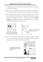
Figure 1 shows the heat flux distributi<strong>on</strong> around an inlet<br />
guide vane <str<strong>on</strong>g>and</str<strong>on</strong>g> a rotor blade. At the leading edge <str<strong>on</strong>g>of</str<strong>on</strong>g> the vane,<br />
the heat transfer coefficients are very high, <str<strong>on</strong>g>and</str<strong>on</strong>g> as the flow<br />
splits <str<strong>on</strong>g>and</str<strong>on</strong>g> travels al<strong>on</strong>g the vane, the heat flux decreases. Al<strong>on</strong>g<br />
the sucti<strong>on</strong> side <str<strong>on</strong>g>of</str<strong>on</strong>g> the vane, the flow transiti<strong>on</strong>s from laminar<br />
to turbulent, <str<strong>on</strong>g>and</str<strong>on</strong>g> the heat transfer coefficients increase. As the<br />
flow accelerates al<strong>on</strong>g the pressure surface, the heat transfer<br />
coefficients also increase. The trends are similar for the turbine<br />
blade: the heat flux at the leading edge is very high <str<strong>on</strong>g>and</str<strong>on</strong>g><br />
c<strong>on</strong>tinues decrease as the flow travels al<strong>on</strong>g the blade; <strong>on</strong> the<br />
sucti<strong>on</strong> surface, the flow transiti<strong>on</strong>s from laminar to turbulent,<br />
<str<strong>on</strong>g>and</str<strong>on</strong>g> the heat flux sharply increases; the heat transfer <strong>on</strong> the<br />
pressure surface increases as the flow accelerates around the<br />
blade.<br />
Fig. 1. Cross-Secti<strong>on</strong>al View <str<strong>on</strong>g>and</str<strong>on</strong>g> Heat Flux Distributi<strong>on</strong> <str<strong>on</strong>g>of</str<strong>on</strong>g><br />
a Cooled Vane <str<strong>on</strong>g>and</str<strong>on</strong>g> Blade<br />
PROBLEM STATEMENT<br />
New internal heat transfer data is needed to improve<br />
current rotor blade cooling performance. And also detailed flow<br />
<str<strong>on</strong>g>and</str<strong>on</strong>g> heat transfer data is necessary to underst<str<strong>on</strong>g>and</str<strong>on</strong>g> the flow<br />
physics <str<strong>on</strong>g>and</str<strong>on</strong>g> to improve the current internal cooling designs.<br />
Many techniques have been developed to enhance the heat<br />
transfer in these passages. The cooling passages located in the<br />
middle <str<strong>on</strong>g>of</str<strong>on</strong>g> the airfoils are <str<strong>on</strong>g>of</str<strong>on</strong>g>ten lined with rib turbulators. Near<br />
the leading edge <str<strong>on</strong>g>of</str<strong>on</strong>g> the blade, jet impingement (coupled with<br />
film cooling) is comm<strong>on</strong>ly used. Jet impingement is also used<br />
throughout the cross-secti<strong>on</strong> <str<strong>on</strong>g>of</str<strong>on</strong>g> the stator vanes. Pin-fins <str<strong>on</strong>g>and</str<strong>on</strong>g><br />
dimples can be used in the trailing edge porti<strong>on</strong> <str<strong>on</strong>g>of</str<strong>on</strong>g> the vanes<br />
<str<strong>on</strong>g>and</str<strong>on</strong>g> blades. These techniques have also been combined to<br />
further increase the heat transfer from the airfoil walls.<br />
A typical cooled turbine vane is shown in figure 2. As<br />
shown in the figure, the vane is hollow, so cooling air can pass<br />
through the vane internally. The coolant is extracted from the<br />
internal channel for impingement <str<strong>on</strong>g>and</str<strong>on</strong>g> pin-fin cooling. Jet<br />
impingement is a very aggressive cooling technique which very<br />
effectively removes heat from the vane wall. However, this<br />
technique is not readily applied to the narrow trailing edge. The<br />
vane trailing edge is cooled using pin-fins (an array <str<strong>on</strong>g>of</str<strong>on</strong>g> short<br />
cylinders). The pin-fins increase the heat transfer area while<br />
Copyright © 2013 by Chengl<strong>on</strong>g Wang
effectively mixing the coolant air to lower the wall temperature<br />
<str<strong>on</strong>g>of</str<strong>on</strong>g> the vanes. After impinging <strong>on</strong> the walls <str<strong>on</strong>g>of</str<strong>on</strong>g> the airfoil, the<br />
coolant exits the vane <str<strong>on</strong>g>and</str<strong>on</strong>g> provides a protective film <strong>on</strong> the<br />
vane’s external surface. Similarly, the coolant traveling through<br />
the pin-fin array is ejected from the trailing edge <str<strong>on</strong>g>of</str<strong>on</strong>g> the airfoil.<br />
lined with rib turbulators. Jet impingement is used to cool the<br />
leading edge <str<strong>on</strong>g>of</str<strong>on</strong>g> the blade, <str<strong>on</strong>g>and</str<strong>on</strong>g> pin-fin cooling with ejecti<strong>on</strong> is<br />
used near the trailing edge. Although the techniques used to<br />
cool the blades are similar to those used to cool the vanes, the<br />
heat transfer trends in the vanes <str<strong>on</strong>g>and</str<strong>on</strong>g> blades are very different.<br />
Because the blades are rotating, the flow <str<strong>on</strong>g>of</str<strong>on</strong>g> the coolant in the<br />
passages is altered. Therefore, the effect <str<strong>on</strong>g>of</str<strong>on</strong>g> rotati<strong>on</strong> <strong>on</strong> the<br />
internal heat transfer enhancement must be c<strong>on</strong>sidered.<br />
LITERATURE SURVEY<br />
A number <str<strong>on</strong>g>of</str<strong>on</strong>g> traditi<strong>on</strong>al cooling c<strong>on</strong>cepts are used in<br />
various combinati<strong>on</strong>s to adequately cool the turbine vanes <str<strong>on</strong>g>and</str<strong>on</strong>g><br />
blades; these techniques are identified <str<strong>on</strong>g>and</str<strong>on</strong>g> described in many<br />
papers <str<strong>on</strong>g>and</str<strong>on</strong>g> books. People who are interested can refer to the<br />
book ‘<strong>Gas</strong> <strong>Turbine</strong> Heat Transfer <str<strong>on</strong>g>and</str<strong>on</strong>g> <str<strong>on</strong>g>Cooling</str<strong>on</strong>g> Technology’ by<br />
Han et al., for a more in depth descripti<strong>on</strong> <str<strong>on</strong>g>of</str<strong>on</strong>g> turbine blade heat<br />
transfer <str<strong>on</strong>g>and</str<strong>on</strong>g> cooling [1]. In additi<strong>on</strong>, Lakshminarayana<br />
reviewed recent publicati<strong>on</strong>s involving turbine cooling <str<strong>on</strong>g>and</str<strong>on</strong>g> heat<br />
transfer, <str<strong>on</strong>g>and</str<strong>on</strong>g> Dunn put together a detailed review <str<strong>on</strong>g>of</str<strong>on</strong>g> c<strong>on</strong>vective<br />
heat transfer <str<strong>on</strong>g>and</str<strong>on</strong>g> aerodynamics in axial flow turbines [2,3]. A<br />
symposium volume discussing heat transfer in gas turbine<br />
systems is also available by Goldstein [4].<br />
Fig. 2. Schematic <str<strong>on</strong>g>of</str<strong>on</strong>g> a <strong>Turbine</strong> Vane Cross-Secti<strong>on</strong><br />
with Impingement <str<strong>on</strong>g>and</str<strong>on</strong>g> Trailing Edge Pin-Fin <str<strong>on</strong>g>Cooling</str<strong>on</strong>g><br />
Fig. 3. Schematic <str<strong>on</strong>g>of</str<strong>on</strong>g> a Modern <strong>Gas</strong> <strong>Turbine</strong> Blade<br />
with Comm<strong>on</strong> <str<strong>on</strong>g>Cooling</str<strong>on</strong>g> Techniques<br />
Figure 3 shows several techniques to cool a modern gas<br />
turbine blade. The blade c<strong>on</strong>sists <str<strong>on</strong>g>of</str<strong>on</strong>g> serpentine cooling passages<br />
PROJECT DESCRIPTION<br />
Rib Turbulated <str<strong>on</strong>g>Cooling</str<strong>on</strong>g><br />
Rib turbulators are the most frequently used method to<br />
enhance the heat transfer in the internal serpentine cooling<br />
passages. The rib turbulence promoters are typically cast <strong>on</strong><br />
two opposite walls <str<strong>on</strong>g>of</str<strong>on</strong>g> the cooling passage. Heat that c<strong>on</strong>ducts<br />
from the pressure <str<strong>on</strong>g>and</str<strong>on</strong>g> sucti<strong>on</strong> surfaces through the blade walls<br />
is transferred to the coolant passing internally through the blade.<br />
The heat transfer performance <str<strong>on</strong>g>of</str<strong>on</strong>g> the ribbed channel depends <strong>on</strong><br />
the channel aspect ratio, the rib c<strong>on</strong>figurati<strong>on</strong>s, <str<strong>on</strong>g>and</str<strong>on</strong>g> the<br />
Reynolds number <str<strong>on</strong>g>of</str<strong>on</strong>g> the coolant flow. Many fundamental<br />
studies have been c<strong>on</strong>ducted to underst<str<strong>on</strong>g>and</str<strong>on</strong>g> the coolant flow<br />
through a stati<strong>on</strong>ary ribbed channel [5,6,7,8]. The studies show<br />
as the coolant passes over a rib oriented 90° to the mainstream<br />
flow, the flow near the channel wall separates. Reattachment<br />
follows the separati<strong>on</strong>, <str<strong>on</strong>g>and</str<strong>on</strong>g> the boundary layer reattaches to the<br />
channel wall; this thinner, reattached boundary layer results in<br />
increased heat transfer coefficients in the ribbed channel. This<br />
rib induced sec<strong>on</strong>dary flow is shown in figure 4. If the rib<br />
turbulators are skewed to the mainstream flow directi<strong>on</strong>,<br />
counter-rotating vortices are created. Figure 4 shows in a<br />
channel with angled ribs, two counter-rotating vortices are<br />
formed in the cross-secti<strong>on</strong> <str<strong>on</strong>g>of</str<strong>on</strong>g> the cooling passage. However, if<br />
V-shaped rib turbulators are used, four vortices are generated.<br />
The additi<strong>on</strong>al set <str<strong>on</strong>g>of</str<strong>on</strong>g> counter-rotating vortices associated with<br />
the V-shaped ribs results in more heat transfer enhancement in<br />
a channel with V-shaped ribs than angled ribs. The ribs also<br />
create turbulent mixing in the areas <str<strong>on</strong>g>of</str<strong>on</strong>g> flow separati<strong>on</strong>. With<br />
this additi<strong>on</strong>al mixing, the heat is more effectively dissipated<br />
from the wall, <str<strong>on</strong>g>and</str<strong>on</strong>g> thus additi<strong>on</strong>al heat transfer enhancement.<br />
Because <strong>on</strong>ly the flow near the wall <str<strong>on</strong>g>of</str<strong>on</strong>g> the cooling channel is<br />
Copyright © 2013 by Chengl<strong>on</strong>g Wang
disturbed by the ribs, the pressure drop penalty by ribs<br />
affordable.<br />
calculated, <str<strong>on</strong>g>and</str<strong>on</strong>g> substituted into the following equati<strong>on</strong> to<br />
determine f, the four ribbed wall fricti<strong>on</strong> factor.<br />
Fig. 4. A Typical Test Model for Turbulated <str<strong>on</strong>g>Cooling</str<strong>on</strong>g><br />
Studies with Rib Induced Sec<strong>on</strong>dary Flow<br />
( ) ( ) (1)<br />
From f (the fricti<strong>on</strong> factor in a channel with ribs <strong>on</strong> all four<br />
walls) <str<strong>on</strong>g>and</str<strong>on</strong>g> the channel geometry (H/W), the average fricti<strong>on</strong><br />
factor in a channel with ribs <strong>on</strong> two walls, f , can be calculated<br />
using Eqn. 2.<br />
̅ ( ) ̅ (2)<br />
The fricti<strong>on</strong> factor in a channel with smooth walls, fs, is known<br />
from the existing Blasius correlati<strong>on</strong> for smooth channel flow.<br />
Using the four ribbed wall fricti<strong>on</strong> factor, f, the rib height,<br />
e/D, <str<strong>on</strong>g>and</str<strong>on</strong>g> the Reynolds number <str<strong>on</strong>g>of</str<strong>on</strong>g> the coolant flow, Re, the<br />
roughness Reynolds number, e+, can be calculated using the<br />
definiti<strong>on</strong> shown in figure 8. From e+ the top figure can be used<br />
to obtain G, the heat transfer roughness functi<strong>on</strong>, <str<strong>on</strong>g>and</str<strong>on</strong>g> Eqn. 3<br />
can be used to calculate the Stant<strong>on</strong> number <strong>on</strong> the ribbed walls,<br />
Str.<br />
The correlati<strong>on</strong> shown in figure 8 is for a Pr<str<strong>on</strong>g>and</str<strong>on</strong>g>tl number <str<strong>on</strong>g>of</str<strong>on</strong>g><br />
0.703. Because G is inversely proporti<strong>on</strong>al to the Stant<strong>on</strong><br />
number, a low heat transfer roughness functi<strong>on</strong> implies high<br />
heat transfer from the cooling passage wall.<br />
(3)<br />
With the underst<str<strong>on</strong>g>and</str<strong>on</strong>g>ing that skewed ribs yield higher heat<br />
transfer enhancement than orthog<strong>on</strong>al ribs, these correlati<strong>on</strong>s<br />
were extended to include the effect <str<strong>on</strong>g>of</str<strong>on</strong>g> the rib angle. Figure 6<br />
shows the correlati<strong>on</strong>s taking into account the rib angle, α.<br />
From the rib angle (α), rib spacing (P/e), <str<strong>on</strong>g>and</str<strong>on</strong>g> channel aspect<br />
ratio (W/H), the roughness functi<strong>on</strong>, R, can be determined. Eqn.<br />
1 can used to calculate f, <str<strong>on</strong>g>and</str<strong>on</strong>g> Eqn. 2 is used to determine the<br />
fricti<strong>on</strong> factor in a channel with two ribbed walls. Similar to<br />
channels with 90° ribs, R <str<strong>on</strong>g>and</str<strong>on</strong>g> e+ are then used to determine the<br />
Stant<strong>on</strong> number <strong>on</strong> the ribbed walls. These correlati<strong>on</strong>s can be<br />
used over a wide range <str<strong>on</strong>g>of</str<strong>on</strong>g> channel aspect ratios <str<strong>on</strong>g>and</str<strong>on</strong>g> rib<br />
c<strong>on</strong>figurati<strong>on</strong>s; however <strong>on</strong>e should refer to the original papers<br />
for specific restricti<strong>on</strong>s <str<strong>on</strong>g>of</str<strong>on</strong>g> the correlati<strong>on</strong>s.<br />
Fig. 5. Fricti<strong>on</strong> Factor <str<strong>on</strong>g>and</str<strong>on</strong>g> Heat Transfer Coefficient<br />
Correlati<strong>on</strong>s for 90 o Ribs<br />
Han <str<strong>on</strong>g>and</str<strong>on</strong>g> Han <str<strong>on</strong>g>and</str<strong>on</strong>g> Park developed correlati<strong>on</strong>s for both the<br />
pressure penalty <str<strong>on</strong>g>and</str<strong>on</strong>g> heat transfer enhancement in ribbed<br />
channels [7, 8]. Given the Reynolds number <str<strong>on</strong>g>of</str<strong>on</strong>g> the coolant flow<br />
<str<strong>on</strong>g>and</str<strong>on</strong>g> the rib geometry (e/D, P/e, W/H, <str<strong>on</strong>g>and</str<strong>on</strong>g> α), the average<br />
fricti<strong>on</strong> factor in a channel with two opposite ribbed walls, f ,<br />
<str<strong>on</strong>g>and</str<strong>on</strong>g> the centerline average Stant<strong>on</strong> number <strong>on</strong> the ribbed walls,<br />
Str, can be determined from the correlati<strong>on</strong>s. Figure 5<br />
dem<strong>on</strong>strates the correlati<strong>on</strong>s developed for cooling passages<br />
with 90° ribs. The fricti<strong>on</strong> roughness functi<strong>on</strong>, R, is <strong>on</strong>ly a<br />
functi<strong>on</strong> <str<strong>on</strong>g>of</str<strong>on</strong>g> rib spacing for the range <str<strong>on</strong>g>of</str<strong>on</strong>g> the roughness Reynolds<br />
number, e+, shown. Based <strong>on</strong> the rib spacing (P/e), R can be<br />
Fig. 6. Fricti<strong>on</strong> Factor <str<strong>on</strong>g>and</str<strong>on</strong>g> Heat Transfer Coefficient in<br />
Rectangular Ribbed Channels<br />
Copyright © 2013 by Chengl<strong>on</strong>g Wang
Because ribs are the most comm<strong>on</strong> heat transfer<br />
enhancement technique for the serpentine cooling passages,<br />
many studies have been c<strong>on</strong>ducted to study the effects <str<strong>on</strong>g>of</str<strong>on</strong>g><br />
channel cross-secti<strong>on</strong>, rib c<strong>on</strong>figurati<strong>on</strong>, <str<strong>on</strong>g>and</str<strong>on</strong>g> coolant flow<br />
Reynolds number. As shown in figure 6, the aspect ratio <str<strong>on</strong>g>of</str<strong>on</strong>g> the<br />
channels changes from the leading to the trailing edge <str<strong>on</strong>g>of</str<strong>on</strong>g> the<br />
blade. Near the leading edge <str<strong>on</strong>g>of</str<strong>on</strong>g> the blade, the channel may have<br />
an aspect ratio around ¼, but near the trailing edge, much<br />
broader channels are present with aspect ratios around 4.<br />
Multiple studies have shown that by skewing the ribs, so<br />
they are angled into the mainstream flow, the heat transfer<br />
coefficients can be further enhanced. Placing the ribs with an<br />
attack angle between 30° <str<strong>on</strong>g>and</str<strong>on</strong>g> 60° results in increased heat<br />
transfer <str<strong>on</strong>g>and</str<strong>on</strong>g> reduces the pressure penalty. Most studies focus <strong>on</strong><br />
Reynolds numbers ranging from 10,000 to 80,000, but for<br />
today’s advanced gas turbines the coolant in the channel can<br />
have a Reynolds number up to 500,000. The height <str<strong>on</strong>g>of</str<strong>on</strong>g> the ribs<br />
is typically 5-10% <str<strong>on</strong>g>of</str<strong>on</strong>g> the channel hydraulic diameter, <str<strong>on</strong>g>and</str<strong>on</strong>g> the<br />
rib spacing-to-height ratio varies from 5 to 15. In additi<strong>on</strong>, a<br />
limited number <str<strong>on</strong>g>of</str<strong>on</strong>g> studies have focused <strong>on</strong> the more closely<br />
spaced ribs with much larger blockage ratios.<br />
[9]. Numerous other studies have shown the same c<strong>on</strong>clusi<strong>on</strong><br />
that V-shaped ribs perform better than the traditi<strong>on</strong>al angled<br />
ribs in a variety <str<strong>on</strong>g>of</str<strong>on</strong>g> channels <str<strong>on</strong>g>and</str<strong>on</strong>g> flow c<strong>on</strong>diti<strong>on</strong>s [10]. In an<br />
effort to further increase the heat transfer performance <str<strong>on</strong>g>of</str<strong>on</strong>g> the<br />
rib turbulators, discrete rib c<strong>on</strong>figurati<strong>on</strong>s were introduced.<br />
Figure 7 shows discrete (or broken) ribs are similar to the<br />
traditi<strong>on</strong>al ribs, but they are broken in <strong>on</strong>e or more locati<strong>on</strong>s, so<br />
the rib is not c<strong>on</strong>tinuous. In the majority <str<strong>on</strong>g>of</str<strong>on</strong>g> cooling channels,<br />
discrete ribs were shown to outperform the c<strong>on</strong>tinuous angled<br />
or V-shaped ribs <str<strong>on</strong>g>and</str<strong>on</strong>g> Cho et al. [11]. Han <str<strong>on</strong>g>and</str<strong>on</strong>g> Zhang compared<br />
the performance <str<strong>on</strong>g>of</str<strong>on</strong>g> many high performance rib c<strong>on</strong>figurati<strong>on</strong>s,<br />
<str<strong>on</strong>g>and</str<strong>on</strong>g> the comparis<strong>on</strong> is shown in figure 8 [9]. As shown in this<br />
figure, the broken 45° angled ribs create more heat transfer<br />
enhancement than the c<strong>on</strong>tinuous 45° angled ribs at a given<br />
fricti<strong>on</strong> factor ratio, <str<strong>on</strong>g>and</str<strong>on</strong>g> this c<strong>on</strong>clusi<strong>on</strong> can be extended to<br />
other broken versus c<strong>on</strong>tinuous rib c<strong>on</strong>figurati<strong>on</strong>s.<br />
Fig. 8. Comparis<strong>on</strong> <str<strong>on</strong>g>of</str<strong>on</strong>g> Heat Transfer Performance for<br />
Broken <str<strong>on</strong>g>and</str<strong>on</strong>g> N<strong>on</strong>-Broken Rib C<strong>on</strong>figurati<strong>on</strong>s<br />
Fig. 7. High Performance Rib Turbulators for <strong>Turbine</strong><br />
Blade <str<strong>on</strong>g>Internal</str<strong>on</strong>g> <str<strong>on</strong>g>Cooling</str<strong>on</strong>g><br />
With angled ribs performing superior to orthog<strong>on</strong>al ribs,<br />
many researchers have extended their studies to include a wide<br />
variety <str<strong>on</strong>g>of</str<strong>on</strong>g> rib c<strong>on</strong>figurati<strong>on</strong>s. Han et al. showed that V-shaped<br />
ribs (figure 7) outperform the angled ribs; for a given pressure<br />
drop, the V-shaped ribs give more heat transfer enhancement<br />
Impingement <str<strong>on</strong>g>Cooling</str<strong>on</strong>g><br />
Impingement cooling is comm<strong>on</strong>ly used near the leading<br />
edge <str<strong>on</strong>g>of</str<strong>on</strong>g> the airfoils, where the heat loads are the greatest. With<br />
the cooling jets striking (impinging) the blade wall, the leading<br />
edge is well suited for impingement cooling because <str<strong>on</strong>g>of</str<strong>on</strong>g> the<br />
relatively thick blade wall in this area. Impingement can also be<br />
used near the mid-chord <str<strong>on</strong>g>of</str<strong>on</strong>g> the vane. Figure 2 shows jet<br />
impingement located throughout the cross-secti<strong>on</strong> <str<strong>on</strong>g>of</str<strong>on</strong>g> an inlet<br />
guide vane. Several aspects must be c<strong>on</strong>sidered when<br />
developing efficient cooling designs. The effect <str<strong>on</strong>g>of</str<strong>on</strong>g> jet-hole size<br />
<str<strong>on</strong>g>and</str<strong>on</strong>g> distributi<strong>on</strong>, cooling channel cross-secti<strong>on</strong>, <str<strong>on</strong>g>and</str<strong>on</strong>g> target<br />
surface shape all have significant effects <strong>on</strong> the heat transfer<br />
coefficient distributi<strong>on</strong>. Jet impingement near the mid-chord <str<strong>on</strong>g>of</str<strong>on</strong>g><br />
the blade is very similar to impingement <strong>on</strong> a flat plate;<br />
however, the sharp curvature at the leading edge <str<strong>on</strong>g>of</str<strong>on</strong>g> the vane<br />
must be c<strong>on</strong>sidered when utilizing impingement in this regi<strong>on</strong>.<br />
Copyright © 2013 by Chengl<strong>on</strong>g Wang
As shown in figure 2, many jets are used to increase the<br />
heat transfer from the vane wall. It has been shown by Metzger<br />
et al. that multiple jets perform very differently from a single jet<br />
striking a target surface [12]. They c<strong>on</strong>cluded that for multiple<br />
jets, the Nusselt number is str<strong>on</strong>gly dependent <strong>on</strong> the Reynolds<br />
number, while there is no significant dependence <strong>on</strong> the jet-totarget<br />
plate spacing.<br />
The difference is due to the jet cross-flow from the spent<br />
jets. Studies by Florschuetz et al. <str<strong>on</strong>g>and</str<strong>on</strong>g> Koopman <str<strong>on</strong>g>and</str<strong>on</strong>g> Sparrow<br />
showed that the mass from <strong>on</strong>e jet moves in the cross-jet flow<br />
directi<strong>on</strong>, <str<strong>on</strong>g>and</str<strong>on</strong>g> this flow can alter the performance <str<strong>on</strong>g>of</str<strong>on</strong>g><br />
neighbouring jets5. The cross-flow attempts to deflect a jet<br />
away from its impinging locati<strong>on</strong> <strong>on</strong> the target plate. In<br />
situati<strong>on</strong>s with very str<strong>on</strong>g cross-flow <str<strong>on</strong>g>and</str<strong>on</strong>g> sufficiently large jetto-target<br />
plate spacing, the cross-flow can completely deflect<br />
the jet away from the impingement surface. Florschuetz <str<strong>on</strong>g>and</str<strong>on</strong>g> Su<br />
reported that cross-flow decreases the overall heat transfer from<br />
the impingement surface [13]. They determined that cross-flow<br />
enhances the c<strong>on</strong>vective heat transfer, but the enhancement<br />
from the jets decreases, as the jets are deflected. Because the<br />
enhancement from the impingement jets is much greater than<br />
the c<strong>on</strong>vective enhancement, the overall Nusselt numbers<br />
decrease in the presence <str<strong>on</strong>g>of</str<strong>on</strong>g> cross-flow.<br />
A typical test model used by Florschuetz et al. is shown in<br />
figure 9. As shown in this figure, the coolant jets impinge <strong>on</strong><br />
the target surface from the jet plate in an inline array. As the<br />
coolant travels al<strong>on</strong>g the test surface, the spent air from the<br />
upstream jets effects the heat transfer coefficient distributi<strong>on</strong>s<br />
<str<strong>on</strong>g>of</str<strong>on</strong>g> the downstream jets, <str<strong>on</strong>g>and</str<strong>on</strong>g> this effect increases as more spent<br />
air accumulates <strong>on</strong> the target surface.<br />
Fig. 9. A Typical Test Model for Impingement <str<strong>on</strong>g>Cooling</str<strong>on</strong>g><br />
Studies<br />
Correlati<strong>on</strong>s based <strong>on</strong> experimental data were developed<br />
by Kercher <str<strong>on</strong>g>and</str<strong>on</strong>g> Tabak<str<strong>on</strong>g>of</str<strong>on</strong>g>f <str<strong>on</strong>g>and</str<strong>on</strong>g> Florschuetz et al. to estimate the<br />
heat transfer enhancement from an array <str<strong>on</strong>g>of</str<strong>on</strong>g> impinging jets [14].<br />
Although the correlati<strong>on</strong>s are in different forms, they both<br />
dem<strong>on</strong>strate the dependence <str<strong>on</strong>g>of</str<strong>on</strong>g> the heat transfer enhancement<br />
<strong>on</strong> the amount <str<strong>on</strong>g>of</str<strong>on</strong>g> cross-flow. Florschuetz et al. also showed the<br />
cross-flow effect is much str<strong>on</strong>ger in staggered arrays <str<strong>on</strong>g>of</str<strong>on</strong>g> jets<br />
than an inline array [15]. Bailey <str<strong>on</strong>g>and</str<strong>on</strong>g> Bunker extended the<br />
correlati<strong>on</strong> developed by Florschuetz et al. to include the effect<br />
<str<strong>on</strong>g>of</str<strong>on</strong>g> jet spacing [16]. The correlati<strong>on</strong> has been extended to<br />
include dense impingement arrays.<br />
Huang et al. c<strong>on</strong>trolled the directi<strong>on</strong> <str<strong>on</strong>g>of</str<strong>on</strong>g> the cross-flow <str<strong>on</strong>g>and</str<strong>on</strong>g><br />
obtained detailed distributi<strong>on</strong>s <str<strong>on</strong>g>of</str<strong>on</strong>g> the heat transfer coefficients<br />
for three target plates [17]. Their results clearly indicate when<br />
the cross-flow travels in two opposite directi<strong>on</strong>s, the heat<br />
transfer enhancement <strong>on</strong> the target plate is much greater than<br />
when the cross-flow is restricted to <strong>on</strong>e directi<strong>on</strong>. This study<br />
was extended by Ekkad et al. to include the effect <str<strong>on</strong>g>of</str<strong>on</strong>g> coolant<br />
extracti<strong>on</strong> for film cooling [18]. The heat transfer enhancement<br />
<strong>on</strong> the target plate decreases near the edges due to the decreased<br />
coolant flow (for film cooling). Wang et al. investigated crossflow<br />
through a c<strong>on</strong>fined space; they also c<strong>on</strong>sidered cross-flow<br />
traveling in <strong>on</strong>e directi<strong>on</strong> <str<strong>on</strong>g>and</str<strong>on</strong>g> two directi<strong>on</strong>s [19]. This study<br />
also c<strong>on</strong>cluded that increasing cross-flow results in degraded<br />
heat transfer; however, the heat transfer coefficient distributi<strong>on</strong><br />
is much more uniform.The heat transfer coefficient<br />
distributi<strong>on</strong>s <strong>on</strong> target plates with stretched arrays <str<strong>on</strong>g>of</str<strong>on</strong>g> impinging<br />
jets were studied by Gao et al.[20]. This array varies from the<br />
traditi<strong>on</strong>al square array in which the jets are evenly spaced.<br />
They c<strong>on</strong>cluded the existing correlati<strong>on</strong>s for square arrays overpredict<br />
the effect <str<strong>on</strong>g>of</str<strong>on</strong>g> cross-flow in the target surface. The<br />
presence <str<strong>on</strong>g>of</str<strong>on</strong>g> initial cross-flow also effects the heat transfer<br />
enhancement from the target plate. The cross-flow described<br />
above is created by the spent flow from the jets. Therefore, the<br />
first row <str<strong>on</strong>g>of</str<strong>on</strong>g> jets is not affected by the cross-flow. However, in<br />
many situati<strong>on</strong>s, cross-flow may develop upstream <str<strong>on</strong>g>of</str<strong>on</strong>g> the first<br />
row. The flow from upstream <str<strong>on</strong>g>of</str<strong>on</strong>g> the impingement jets can<br />
significantly alter the flow near the jets, <str<strong>on</strong>g>and</str<strong>on</strong>g> thus alter the heat<br />
transfer coefficients <strong>on</strong> the target surface. Florschuetz et al.<br />
investigated the effect <str<strong>on</strong>g>of</str<strong>on</strong>g> initial cross-flow <strong>on</strong> the heat transfer<br />
enhancement [21]. The results <str<strong>on</strong>g>of</str<strong>on</strong>g> this study were similar to<br />
those menti<strong>on</strong>ed above describing cross-flow: the heat transfer<br />
enhancement <strong>on</strong> the target plate decreases when initial crossflow<br />
is present.<br />
The above studies investigated the heat transfer <strong>on</strong> flat<br />
target plates. The results obtained for flat plates can be applied<br />
to impingement near the mid-chord <str<strong>on</strong>g>of</str<strong>on</strong>g> the blade. However, the<br />
effect <str<strong>on</strong>g>of</str<strong>on</strong>g> target surface curvature must be c<strong>on</strong>sidered when<br />
implementing jet impingement near the leading edge <str<strong>on</strong>g>of</str<strong>on</strong>g> the<br />
airfoil. The curvature <str<strong>on</strong>g>of</str<strong>on</strong>g> the airfoil creates different cross-flow<br />
behavior, <str<strong>on</strong>g>and</str<strong>on</strong>g> therefore, the heat transfer coefficients <strong>on</strong> the<br />
curved surface are different than those <strong>on</strong> the flat surface.<br />
Chupp et al. studied impingement <strong>on</strong> a curved surface, <str<strong>on</strong>g>and</str<strong>on</strong>g> this<br />
group c<strong>on</strong>cluded that the average Nusselt number ratio<br />
increases as the curvature <str<strong>on</strong>g>of</str<strong>on</strong>g> the target plate increases [22]. The<br />
effect <str<strong>on</strong>g>of</str<strong>on</strong>g> target surface shape was also pursued by Bunker <str<strong>on</strong>g>and</str<strong>on</strong>g><br />
Metzger [23]. They c<strong>on</strong>cluded that a sharper nose radius yields<br />
a more uniform Nusselt number distributi<strong>on</strong> compared to a<br />
smooth-nosed chamber. This study was also extended to<br />
include the effect <str<strong>on</strong>g>of</str<strong>on</strong>g> coolant extracti<strong>on</strong> for film cooling [24].<br />
When the bleed from the pressure <str<strong>on</strong>g>and</str<strong>on</strong>g> sucti<strong>on</strong> surfaces is equal,<br />
the greatest reducti<strong>on</strong> in the Nusselt numbers occurs.<br />
Pin-Fin <str<strong>on</strong>g>Cooling</str<strong>on</strong>g><br />
Copyright © 2013 by Chengl<strong>on</strong>g Wang
Due to manufacturing c<strong>on</strong>straints in the very narrow<br />
trailing edge <str<strong>on</strong>g>of</str<strong>on</strong>g> the blade, pin-fin cooling is typically used to<br />
enhance the heat transfer from the blade wall in this regi<strong>on</strong>. The<br />
pins typically have a height-to-diameter ratio between ½ <str<strong>on</strong>g>and</str<strong>on</strong>g> 4.<br />
In a pin-fin array heat is transferred from both the smooth<br />
channel end-wall <str<strong>on</strong>g>and</str<strong>on</strong>g> the numerous pins. Flow around the pins<br />
in the array is comparable to flow around a single cylinder. As<br />
the coolant flows past the pin, the flow separates <str<strong>on</strong>g>and</str<strong>on</strong>g> wakes are<br />
shed downstream <str<strong>on</strong>g>of</str<strong>on</strong>g> the pin. In additi<strong>on</strong> to this wake formati<strong>on</strong>,<br />
a horseshoe vortex forms just upstream <str<strong>on</strong>g>of</str<strong>on</strong>g> the base <str<strong>on</strong>g>of</str<strong>on</strong>g> the pin,<br />
<str<strong>on</strong>g>and</str<strong>on</strong>g> the vortex wraps around the pins. This horseshoe vortex<br />
creates additi<strong>on</strong>al mixing, <str<strong>on</strong>g>and</str<strong>on</strong>g> thus enhanced heat transfer.<br />
Many factors must be c<strong>on</strong>sidered when investigating pin-fin<br />
cooling. The type <str<strong>on</strong>g>of</str<strong>on</strong>g> pin-fin array <str<strong>on</strong>g>and</str<strong>on</strong>g> the spacing <str<strong>on</strong>g>of</str<strong>on</strong>g> the pins in<br />
the array affect the heat transfer distributi<strong>on</strong> in the channel. The<br />
pin size <str<strong>on</strong>g>and</str<strong>on</strong>g> shape also have a pr<str<strong>on</strong>g>of</str<strong>on</strong>g>ound impact <strong>on</strong> the heat<br />
transfer in the cooling passage. Because pin-fins are comm<strong>on</strong>ly<br />
coupled with trailing edge ejecti<strong>on</strong> (as shown in figure 2), the<br />
effect <str<strong>on</strong>g>of</str<strong>on</strong>g> this coolant extracti<strong>on</strong> must also be c<strong>on</strong>sidered. There<br />
are two array structures comm<strong>on</strong>ly used. One is the inline array<br />
<str<strong>on</strong>g>and</str<strong>on</strong>g> the other is the staggered array. Figure 10 shows a typical<br />
experimental test model with a staggered array <str<strong>on</strong>g>of</str<strong>on</strong>g> pin-fins.<br />
effects <str<strong>on</strong>g>of</str<strong>on</strong>g> partial length pins in a rectangular channel [28]. The<br />
surface c<strong>on</strong>taining pins is not affected by the pin tip clearance.<br />
Whereas the opposite surface, that does not have pins, shows a<br />
decrease in heat transfer coefficient with an increase in the pin<br />
tip clearance. The fricti<strong>on</strong> factor is lower for partial pins<br />
compared to full-length pins. In general, the heat transfer<br />
coefficient decreases with partial length pins.<br />
Dimple <str<strong>on</strong>g>Cooling</str<strong>on</strong>g><br />
In recent years, dimples have been c<strong>on</strong>sidered as an<br />
alternative to pin-fin cooling. Dimpled cooling is a very<br />
desirable alternative due to the relatively low pressure loss<br />
penalty (compared with pins) <str<strong>on</strong>g>and</str<strong>on</strong>g> moderate heat transfer<br />
enhancement.<br />
Fig. 11. A Typical Test Model for Dimple <str<strong>on</strong>g>Cooling</str<strong>on</strong>g><br />
Studies with a C<strong>on</strong>ceptual View <str<strong>on</strong>g>of</str<strong>on</strong>g> Dimple induced Sec<strong>on</strong>dary<br />
Flow<br />
Fig. 10. A Typical Test Model <str<strong>on</strong>g>and</str<strong>on</strong>g> Sec<strong>on</strong>dary Flow for<br />
Pin-Fin <str<strong>on</strong>g>Cooling</str<strong>on</strong>g> Studies<br />
Metzger et al. used staggered arrays <str<strong>on</strong>g>of</str<strong>on</strong>g> circular pins with<br />
1.5 to 5 pin diameter spacing in a rectangular channel [25]. A<br />
closer spaced array (smaller x/D) shows a higher heat transfer<br />
coefficient. Their observati<strong>on</strong>s clearly indicate that additi<strong>on</strong> <str<strong>on</strong>g>of</str<strong>on</strong>g><br />
pin-fins significantly enhances the heat transfer coefficient.<br />
However, the additi<strong>on</strong> <str<strong>on</strong>g>of</str<strong>on</strong>g> pins also increases the pressure drop<br />
in the flow channel. Chyu et al. showed that the heat transfer<br />
coefficient <strong>on</strong> the pin surface for both arrays is c<strong>on</strong>sistently<br />
higher than that <str<strong>on</strong>g>of</str<strong>on</strong>g> the channel end-wall [26]. The pin surface<br />
heat transfer is observed to be 10 to 20 percent higher for the<br />
presented case. Experimental results have been correlated by<br />
Metzger et al. <str<strong>on</strong>g>and</str<strong>on</strong>g> VanFossen to predict the Nusselt number in<br />
channels with pin-fin arrays [27]. The average Nusselt number<br />
in a channel with short pin-fins is primarily dependent <strong>on</strong> the<br />
Reynolds number <str<strong>on</strong>g>of</str<strong>on</strong>g> the flow, <str<strong>on</strong>g>and</str<strong>on</strong>g> a weaker dependence is<br />
shown for the pin spacing. Arora <str<strong>on</strong>g>and</str<strong>on</strong>g> Abdel-Messeh studied the<br />
A typical test secti<strong>on</strong> for dimple cooling studies is shown<br />
in figure 11; this figure also shows the dimple induced<br />
sec<strong>on</strong>dary flow. These c<strong>on</strong>cave dimples induce flow separati<strong>on</strong><br />
<str<strong>on</strong>g>and</str<strong>on</strong>g> reattachment with pairs <str<strong>on</strong>g>of</str<strong>on</strong>g> vortices. The areas <str<strong>on</strong>g>of</str<strong>on</strong>g> high heat<br />
transfer include the areas <str<strong>on</strong>g>of</str<strong>on</strong>g> flow reattachment <strong>on</strong> the flat<br />
surface immediately downstream <str<strong>on</strong>g>of</str<strong>on</strong>g> the dimple. The heat<br />
transfer in the dimpled channel is typically 2 to 2.5 times<br />
greater than the heat transfer in a smooth channel with a<br />
pressure loss penalty <str<strong>on</strong>g>of</str<strong>on</strong>g> 2 to 4 times that <str<strong>on</strong>g>of</str<strong>on</strong>g> a smooth channel.<br />
These values show little dependence <strong>on</strong> Reynolds number <str<strong>on</strong>g>and</str<strong>on</strong>g><br />
channel aspect ratio. However, the dimple size, dimple depth<br />
(depth-to-print diameter ratio = 0.1 to 0.3), distributi<strong>on</strong>, <str<strong>on</strong>g>and</str<strong>on</strong>g><br />
shape (cylindrical, hemispheric, teardrop) each effect the heat<br />
transfer distributi<strong>on</strong> in the channel. Recent studies have<br />
investigated the influence <str<strong>on</strong>g>of</str<strong>on</strong>g> these factors <strong>on</strong> the heat transfer in<br />
rectangular channels [29]. Dimples have also been investigated<br />
in a circular channel <str<strong>on</strong>g>and</str<strong>on</strong>g> similar levels <str<strong>on</strong>g>of</str<strong>on</strong>g> heat transfer<br />
enhancement <str<strong>on</strong>g>and</str<strong>on</strong>g> fricti<strong>on</strong>al losses were measured [30]. Syred et<br />
al. compared the heat transfer enhancement due a single dimple<br />
<strong>on</strong> both flat <str<strong>on</strong>g>and</str<strong>on</strong>g> curved surfaces [31]. From this study it was<br />
shown that the surface curvature significantly influences the<br />
heat transfer enhancement. The heat transfer is further<br />
enhanced <strong>on</strong> a surface that is c<strong>on</strong>cavely shaped (compared to a<br />
flat surface); however, a c<strong>on</strong>vexly curved surface with a dimple<br />
decreases the level <str<strong>on</strong>g>of</str<strong>on</strong>g> heat transfer enhancement.<br />
Overall Comparis<strong>on</strong>s<br />
Figures 12 <str<strong>on</strong>g>and</str<strong>on</strong>g> 13 present comparis<strong>on</strong>s <str<strong>on</strong>g>of</str<strong>on</strong>g> globally<br />
Copyright © 2013 by Chengl<strong>on</strong>g Wang
averaged Nusselt number ratios <str<strong>on</strong>g>and</str<strong>on</strong>g> fricti<strong>on</strong> factor ratios for rib<br />
turbulators, pin fins, swirl chambers, dimple-smooth<br />
arrangements, dimple-protrusi<strong>on</strong> arrangements, dimple-dimple<br />
arrangements, surface roughness, <str<strong>on</strong>g>and</str<strong>on</strong>g> smooth-walled channels.<br />
The fricti<strong>on</strong> ratios scale in Figure 13 ranges from 0 to 20<br />
(compared to 0 to 80 in Figure 12) to provide a detailed view <str<strong>on</strong>g>of</str<strong>on</strong>g><br />
variati<strong>on</strong>s over this fricti<strong>on</strong> factor ratio range [32].<br />
Fig. 12. Comparis<strong>on</strong> <str<strong>on</strong>g>of</str<strong>on</strong>g> relative performance <str<strong>on</strong>g>of</str<strong>on</strong>g> rib<br />
turbulators, pin fins, swirl chambers, dimple-smooth<br />
arrangements, dimpleprotrusi<strong>on</strong> arrangements, dimple-dimple<br />
arrangements, surface roughness, <str<strong>on</strong>g>and</str<strong>on</strong>g> smooth-walled channels<br />
Many <str<strong>on</strong>g>of</str<strong>on</strong>g> the rib turbulator c<strong>on</strong>figurati<strong>on</strong>s produce levels <str<strong>on</strong>g>of</str<strong>on</strong>g> heat<br />
transfer augmentati<strong>on</strong> that are higher than those produced by<br />
the dimple-protrusi<strong>on</strong> smooth c<strong>on</strong>figurati<strong>on</strong>s. However,<br />
generally, the increases in pressure losses due to the rib<br />
turbulators are also larger than those associated with the<br />
dimple-protrusi<strong>on</strong>-smooth c<strong>on</strong>figurati<strong>on</strong>s. Fricti<strong>on</strong> ratios<br />
magnitudes are as highas 71 for channels with rib turbulators,<br />
<str<strong>on</strong>g>and</str<strong>on</strong>g> as high as 25 for swirl chambers, whereas magnitudes for<br />
dimple-protrusi<strong>on</strong>-smooth c<strong>on</strong>figurati<strong>on</strong>s reach <strong>on</strong>ly up to 4.5.<br />
Nusselt number ratios in channels with pin fins lie near the<br />
bottom <str<strong>on</strong>g>of</str<strong>on</strong>g> or below the values for rib turbulators when<br />
compared at the same fricti<strong>on</strong> factor ratio value. Pin fin fricti<strong>on</strong><br />
factor ratios are then as high as 76.<br />
Also included in Figures 12 <str<strong>on</strong>g>and</str<strong>on</strong>g> 13 are Nusselt number<br />
ratios <str<strong>on</strong>g>and</str<strong>on</strong>g> fricti<strong>on</strong> factor ratios for a smooth channel, <str<strong>on</strong>g>and</str<strong>on</strong>g> for a<br />
channel with three-dimensi<strong>on</strong>al, irregular surface roughness.<br />
Such surface roughness augmenters work as micro-turbulators<br />
<str<strong>on</strong>g>and</str<strong>on</strong>g> micro-vortex generators. These act to increase mixing <str<strong>on</strong>g>and</str<strong>on</strong>g><br />
levels <str<strong>on</strong>g>of</str<strong>on</strong>g> turbulence transport locally near surfaces. With this<br />
mechanism, Nusselt number ratios range from1.06 to 1.53, <str<strong>on</strong>g>and</str<strong>on</strong>g><br />
fricti<strong>on</strong> factor ratios range from 1.18 to 1.75 in Figures 12 <str<strong>on</strong>g>and</str<strong>on</strong>g><br />
13.<br />
Combined <str<strong>on</strong>g>and</str<strong>on</strong>g> New <str<strong>on</strong>g>Cooling</str<strong>on</strong>g> Technology<br />
Several internal heat transfer enhancement techniques are<br />
discussed in previous secti<strong>on</strong>s. Most comm<strong>on</strong> methods <str<strong>on</strong>g>of</str<strong>on</strong>g> heat<br />
transfer augmentati<strong>on</strong> in gas turbine airfoils are ribs, pins, <str<strong>on</strong>g>and</str<strong>on</strong>g><br />
jet impingement. It is shown that these enhancement techniques<br />
increase heat transfer coefficients, but can combining these<br />
techniques increase the heat transfer coefficient more?<br />
Several researchers have combined these heat transfer<br />
enhancement techniques to improve the heat transfer<br />
coefficient. However, it is not always recommended to combine<br />
more than <strong>on</strong>e heat transfer augmentati<strong>on</strong> technique. In additi<strong>on</strong><br />
to compounding more than <strong>on</strong>e heat transfer enhancement<br />
technique, there are attempts to incorporate new c<strong>on</strong>cepts (e.g.,<br />
jet swirlers <str<strong>on</strong>g>and</str<strong>on</strong>g> heat pipes) in the turbomachinery cooling. An<br />
introducti<strong>on</strong> <str<strong>on</strong>g>of</str<strong>on</strong>g> several new cooling techniques with their<br />
applicati<strong>on</strong>s is presented here.<br />
Impingement <strong>on</strong> Ribbed, Pinned, <str<strong>on</strong>g>and</str<strong>on</strong>g> Dimpled Walls<br />
Fig. 13. Comparis<strong>on</strong> <str<strong>on</strong>g>of</str<strong>on</strong>g> relative performance <str<strong>on</strong>g>of</str<strong>on</strong>g> rib<br />
turbulators, pin fins, swirl chambers, dimple-smooth<br />
arrangements, dimpleprotrusi<strong>on</strong> arrangements, dimple-dimple<br />
arrangements, surface roughness, <str<strong>on</strong>g>and</str<strong>on</strong>g> smooth-walled channels<br />
According to Ligrani et al. [32], <str<strong>on</strong>g>of</str<strong>on</strong>g> the techniques<br />
c<strong>on</strong>sidered, swirl chambers give some <str<strong>on</strong>g>of</str<strong>on</strong>g> the highest levels <str<strong>on</strong>g>of</str<strong>on</strong>g><br />
heat transfer augmentati<strong>on</strong> when compared at the same value <str<strong>on</strong>g>of</str<strong>on</strong>g><br />
fricti<strong>on</strong> factor ratio. In some cases, several <str<strong>on</strong>g>of</str<strong>on</strong>g> the rib turbulator<br />
c<strong>on</strong>figurati<strong>on</strong>s produce comparable Nusselt number ratios.<br />
However, pressure losses <str<strong>on</strong>g>and</str<strong>on</strong>g> fricti<strong>on</strong> factor ratios associated<br />
with swirl chambers <str<strong>on</strong>g>and</str<strong>on</strong>g> rib turbulators are also relatively high.<br />
Because the dimples <str<strong>on</strong>g>and</str<strong>on</strong>g> pins are circular depressi<strong>on</strong>s <str<strong>on</strong>g>and</str<strong>on</strong>g><br />
protrusi<strong>on</strong>s, respectively, these two target surfaces <str<strong>on</strong>g>of</str<strong>on</strong>g>fer an<br />
interesting comparis<strong>on</strong> <str<strong>on</strong>g>of</str<strong>on</strong>g> the heat transfer enhancement. At<br />
lower Reynolds number the pinned surface performs better than<br />
the dimpled surface. At higher Reynolds numbers, the dimpled<br />
surface performs better than the pinned surface for a certain<br />
flow orientati<strong>on</strong>. Taslim et al. reported a significant increase in<br />
the heat transfer enhancement <strong>on</strong> a curved target surface<br />
roughened with c<strong>on</strong>ical bumps [33]. This study was extended to<br />
include film cooling holes, similar to the showerhead-type film<br />
cooling <strong>on</strong> the leading edge. They c<strong>on</strong>cluded that the presence<br />
<str<strong>on</strong>g>of</str<strong>on</strong>g> leading edge extracti<strong>on</strong> also significantly increases the heat<br />
transfer <strong>on</strong> the target surface.<br />
Copyright © 2013 by Chengl<strong>on</strong>g Wang
Combined Effect <str<strong>on</strong>g>of</str<strong>on</strong>g> Swirl <str<strong>on</strong>g>and</str<strong>on</strong>g> Impingement<br />
A new jet impingement <str<strong>on</strong>g>and</str<strong>on</strong>g> swirl technique was<br />
investigated by Glezer et al. [34]. A preliminary test showed<br />
significant improvement in the heat transfer performance.<br />
Based <strong>on</strong> that study, a new airfoil has been designed with<br />
swirling impingement in the leading edge. This new airfoil is<br />
tested in a hot cascade test secti<strong>on</strong>. Results indicate that screw<br />
shaped swirl cooling can significantly improve the heat transfer<br />
coefficient over a smooth channel <str<strong>on</strong>g>and</str<strong>on</strong>g> this improvement is not<br />
significantly dependent <strong>on</strong> the temperature ratio <str<strong>on</strong>g>and</str<strong>on</strong>g> rotati<strong>on</strong>al<br />
forces. Moreover, it was c<strong>on</strong>cluded that optimizati<strong>on</strong> <str<strong>on</strong>g>of</str<strong>on</strong>g> the<br />
internal passage geometry in relati<strong>on</strong> to locati<strong>on</strong> <str<strong>on</strong>g>and</str<strong>on</strong>g> size <str<strong>on</strong>g>of</str<strong>on</strong>g> the<br />
tangential slots is very important in achieving the best<br />
performance <str<strong>on</strong>g>of</str<strong>on</strong>g> the screw-shaped swirl in the leading edge<br />
cooling.<br />
Combined Effect <str<strong>on</strong>g>of</str<strong>on</strong>g> Swirl Flow <str<strong>on</strong>g>and</str<strong>on</strong>g> Ribs<br />
Kieda et al. experimentally investigated the single-phase<br />
water flow <str<strong>on</strong>g>and</str<strong>on</strong>g> heat transfer in a rectangular cross-secti<strong>on</strong>ed<br />
twisted channel [35]. Several aspect ratios <str<strong>on</strong>g>and</str<strong>on</strong>g> twist pitches<br />
were used. Results indicate that in a cooling applicati<strong>on</strong>, this<br />
twisted channel performs similar to a ribbed pipe. Zhang et al.<br />
used different types <str<strong>on</strong>g>of</str<strong>on</strong>g> inserts to study the combined rib <str<strong>on</strong>g>and</str<strong>on</strong>g><br />
twisted tape inserts in square ducts [36]. Four test<br />
c<strong>on</strong>figurati<strong>on</strong>s were used: twisted tape, twisted tape with<br />
interrupted ribs, hemi-circular wavy tape, <str<strong>on</strong>g>and</str<strong>on</strong>g> hemi-triangular<br />
wavy tape. The twisted tape with interrupted ribs provides<br />
higher overall heat transfer performance over the twisted tape<br />
without ribs <str<strong>on</strong>g>and</str<strong>on</strong>g> hemi-circular wavy tape. The performance <str<strong>on</strong>g>of</str<strong>on</strong>g><br />
the hemi-triangular wavy tape is comparable with the twisted<br />
tape plus interrupted ribs. Hemi-circular wavy tapes show the<br />
lowest heat transfer performance in this group.<br />
New <str<strong>on</strong>g>Cooling</str<strong>on</strong>g> C<strong>on</strong>cepts<br />
Heat pipes have very high effective thermal performance<br />
[37]. Therefore, they can transfer heat from high temperature to<br />
the low temperature regi<strong>on</strong>s. This c<strong>on</strong>cept may be used in the<br />
airfoil cooling. Heat is removed from the initial stage stator<br />
airfoils <str<strong>on</strong>g>and</str<strong>on</strong>g> the heat is delivered at a later stage to heat up the<br />
main flow. This way the heat extracted can be recycled to the<br />
main flow. In a c<strong>on</strong>cept developed by Yamawaki et al., the heat<br />
is c<strong>on</strong>ducted away from the hot airfoil to the fin assembly [38].<br />
This passive heat extracti<strong>on</strong> reduces the required cooling air.<br />
Most heat pipe applicati<strong>on</strong>s are designed for the stator airfoils,<br />
where it is easier to mount the c<strong>on</strong>necting pipes or fins.<br />
Comm<strong>on</strong>ly a closed loop steam cooled nozzle with thermal<br />
barrier coatings (TBC) is used in order to reduce the hot gas<br />
temperature drop through the first stage nozzle.<br />
CONCLUSIONS<br />
The internal heat transfer can be enhanced with jet<br />
impingement, pin-fin cooling (used in the trailing edge), <str<strong>on</strong>g>and</str<strong>on</strong>g><br />
internal passages lined with turbulence promoters.<br />
More studies are needed for the effect <str<strong>on</strong>g>of</str<strong>on</strong>g> rotati<strong>on</strong> in ribbed<br />
channels, cooling channels with dimples, jet impingement <str<strong>on</strong>g>and</str<strong>on</strong>g><br />
pin-fin cooling. And in the recent years, such studies have<br />
become available. More studies are needed for the blade-shaped<br />
coolant passages with high performance turbulators <str<strong>on</strong>g>and</str<strong>on</strong>g> with or<br />
without film cooling holes under realistic coolant flow, thermal,<br />
<str<strong>on</strong>g>and</str<strong>on</strong>g> rotating c<strong>on</strong>diti<strong>on</strong>s. Also, more studies are needed for<br />
rotating impingement cooling with or without film coolant<br />
extracti<strong>on</strong> as well as rotating pin-fin cooling with or without<br />
trailing edge ejecti<strong>on</strong> in order to guide the efficient rotor blade<br />
internal cooling designs.<br />
REFERENCES<br />
[1] J.C. Han, S. Dutta, <str<strong>on</strong>g>and</str<strong>on</strong>g> S.V. Ekkad, 2000, “<strong>Gas</strong><br />
<strong>Turbine</strong> Heat Transfer <str<strong>on</strong>g>and</str<strong>on</strong>g> <str<strong>on</strong>g>Cooling</str<strong>on</strong>g> Technology,”<br />
Taylor & Francis, Inc., New York, New York, ISBN #<br />
1-56032-841-X, 646 pages. Book<br />
[2] B. Lakshminryana, 1996, “<strong>Turbine</strong> <str<strong>on</strong>g>Cooling</str<strong>on</strong>g> <str<strong>on</strong>g>and</str<strong>on</strong>g> Heat<br />
Transfer,” Fluid Dynamics <str<strong>on</strong>g>and</str<strong>on</strong>g> Heat Transfer <str<strong>on</strong>g>of</str<strong>on</strong>g><br />
Turbomachinery, John Wiley, New York, pp. 597-721.<br />
Journal article<br />
[3] M.G. Dunn, 2001, “C<strong>on</strong>vecti<strong>on</strong> Heat Transfer <str<strong>on</strong>g>and</str<strong>on</strong>g><br />
Aerodynamics in Axial Flow <strong>Turbine</strong>s, ” ASME<br />
Journal <str<strong>on</strong>g>of</str<strong>on</strong>g> Turbomachinery. 123 no.4:637-686.<br />
[4] R.J. Goldstein, 2001, “Heat Transfer in <strong>Gas</strong> <strong>Turbine</strong><br />
Systems,” Annuals <str<strong>on</strong>g>of</str<strong>on</strong>g> The New York Academy <str<strong>on</strong>g>of</str<strong>on</strong>g><br />
Sciences, New York, New York, Vol. 934, 520 pages.<br />
Book<br />
[5] J.C. Han, L.R. Glicksman, <str<strong>on</strong>g>and</str<strong>on</strong>g> W.M. Rohsenow, 1978,<br />
“An Investigati<strong>on</strong> <str<strong>on</strong>g>of</str<strong>on</strong>g> Heat Transfer <str<strong>on</strong>g>and</str<strong>on</strong>g> Fricti<strong>on</strong> for<br />
Rib-Roughened Surfaces,” Internati<strong>on</strong>al Journal <str<strong>on</strong>g>of</str<strong>on</strong>g><br />
Heat <str<strong>on</strong>g>and</str<strong>on</strong>g> Mass Transfer 21: 1143-1156. Journal article<br />
[6] J.C. Han, J.S. Park, <str<strong>on</strong>g>and</str<strong>on</strong>g> C.K. Lei, 1985, “Heat<br />
Transfer Enhancement in Channels with Turbulence<br />
Promoters,” ASME Journal <str<strong>on</strong>g>of</str<strong>on</strong>g> Engineering for <strong>Gas</strong><br />
<strong>Turbine</strong>s <str<strong>on</strong>g>and</str<strong>on</strong>g> Power 107: 628-635. Journal article<br />
[7] J.C. Han, 1988, “ Heat Transfer <str<strong>on</strong>g>and</str<strong>on</strong>g> Fricti<strong>on</strong><br />
Characteristics in Rectangular Channels with Rib<br />
Turbulators,” ASME Journal <str<strong>on</strong>g>of</str<strong>on</strong>g> Heat Transfer 110:<br />
321-328. Journal article<br />
[8] J.C. Han <str<strong>on</strong>g>and</str<strong>on</strong>g> J.S. Park, 1988, “ Developing Heat<br />
Transfer in Rectangular Channels with Rib<br />
Turbulators,” Internati<strong>on</strong>al Journal <str<strong>on</strong>g>of</str<strong>on</strong>g> Heat <str<strong>on</strong>g>and</str<strong>on</strong>g> Mass<br />
Transfer 31: 183-195. Journal article<br />
[9] J.C. Han, Y.M. Zhang, <str<strong>on</strong>g>and</str<strong>on</strong>g> C.P. Lee, 1991, “<br />
Augmented Heat Transfer in Square Channels with<br />
Parallel, Crossed, <str<strong>on</strong>g>and</str<strong>on</strong>g> V-shaped Angled Ribs, ”<br />
Journal <str<strong>on</strong>g>of</str<strong>on</strong>g> Heat Transfer, Transacti<strong>on</strong>s ASME 113:<br />
590-596. Journal article<br />
Copyright © 2013 by Chengl<strong>on</strong>g Wang
[10] S.C. Lau, R.T. Kukreja, <str<strong>on</strong>g>and</str<strong>on</strong>g> R.D. McMillin, 1991, “<br />
Effects <str<strong>on</strong>g>of</str<strong>on</strong>g> V-shaped Rib Arrays <strong>on</strong> Turbulent Heat<br />
Transfer <str<strong>on</strong>g>and</str<strong>on</strong>g> Fricti<strong>on</strong> <str<strong>on</strong>g>of</str<strong>on</strong>g> Fully Developed Flow in a<br />
Square Channel,” Internati<strong>on</strong>al Journal <str<strong>on</strong>g>of</str<strong>on</strong>g> Heat <str<strong>on</strong>g>and</str<strong>on</strong>g><br />
Mass Transfer 34: 1605-1616. Journal article<br />
[11] H.H. Cho, S.J. Wu, <str<strong>on</strong>g>and</str<strong>on</strong>g> H.J. Kw<strong>on</strong>, 2000, “Local<br />
Heat/Mass Transfer Measurements in a Rectangular<br />
Duct with Discrete Ribs, ” ASME Journal <str<strong>on</strong>g>of</str<strong>on</strong>g><br />
Turbomachinery 122: 579-586. Journal article<br />
[12] D.E. Metzger, L.W. Florschuetz, D.I. Takeuchi, R.D.<br />
Behee, <str<strong>on</strong>g>and</str<strong>on</strong>g> R.A. Berry, 1979, “ Heat Transfer<br />
Characteristics for Inline <str<strong>on</strong>g>and</str<strong>on</strong>g> Staggered Arrays <str<strong>on</strong>g>of</str<strong>on</strong>g><br />
Circular Jets with Crossflow <str<strong>on</strong>g>of</str<strong>on</strong>g> Spent Air,” ASME<br />
Journal <str<strong>on</strong>g>of</str<strong>on</strong>g> Heat Transfer, 101: 526-531. Journal article<br />
[13] L.W. Florschuetz <str<strong>on</strong>g>and</str<strong>on</strong>g> C.C. Su, 1987, “Effects <str<strong>on</strong>g>of</str<strong>on</strong>g><br />
Crossflow Temperature <strong>on</strong> Heat Transfer Within an<br />
Array <str<strong>on</strong>g>of</str<strong>on</strong>g> Impinging Jets,” ASME Journal <str<strong>on</strong>g>of</str<strong>on</strong>g> Heat<br />
Transfer 109: 74-82. Journal article<br />
[14] D.M. Kercher <str<strong>on</strong>g>and</str<strong>on</strong>g> W. Tabak<str<strong>on</strong>g>of</str<strong>on</strong>g>f, 1970, “ Heat<br />
Transfer by a Square Array <str<strong>on</strong>g>of</str<strong>on</strong>g> Round Air Jets<br />
Impinging Perpendicular to a Flat Surface Including<br />
the Effect <str<strong>on</strong>g>of</str<strong>on</strong>g> Spent Air, ” ASME Journal <str<strong>on</strong>g>of</str<strong>on</strong>g><br />
Engineering for Power, Vol. 92 : 73-82. Journal article<br />
[15] Florschuetz, C.R. Truman, <str<strong>on</strong>g>and</str<strong>on</strong>g> D.E. Metzger, 1981,<br />
“Streamwise Flow <str<strong>on</strong>g>and</str<strong>on</strong>g> Heat Transfer Distributi<strong>on</strong>s<br />
for Jet Array Impingement with Crossflow,” ASME<br />
Journal <str<strong>on</strong>g>of</str<strong>on</strong>g> Heat Transfer 103: 337-342. Journal article<br />
[16] J.C. Bailey <str<strong>on</strong>g>and</str<strong>on</strong>g> R.S. Bunker, 2002, “Local Heat<br />
Transfer <str<strong>on</strong>g>and</str<strong>on</strong>g> Flow Distributi<strong>on</strong>s for Impinging Jet<br />
Arrays <str<strong>on</strong>g>of</str<strong>on</strong>g> Dense <str<strong>on</strong>g>and</str<strong>on</strong>g> Sparse Extent,” ASME Paper<br />
No. GT-2002-30473. Paper in C<strong>on</strong>ference<br />
Proceedings<br />
[17] Y. Huang, S.V. Ekkad, <str<strong>on</strong>g>and</str<strong>on</strong>g> J.C. Han, 1998, “Detailed<br />
Heat Transfer Distributi<strong>on</strong>s Under an Array <str<strong>on</strong>g>of</str<strong>on</strong>g><br />
Orthog<strong>on</strong>al Impinging Jets, ” AIAA Journal <str<strong>on</strong>g>of</str<strong>on</strong>g><br />
Thermophysics <str<strong>on</strong>g>and</str<strong>on</strong>g> Heat Transfer 12: pp. 73-79.<br />
Journal article<br />
[18] S.V. Ekkad, Y. Huang, <str<strong>on</strong>g>and</str<strong>on</strong>g> J.C. Han, 1999, “<br />
Impingement Heat Transfer <strong>on</strong> a Target Plate with<br />
Film Holes,” AIAA Journal <str<strong>on</strong>g>of</str<strong>on</strong>g> Thermophysics <str<strong>on</strong>g>and</str<strong>on</strong>g><br />
Heat Transfer 13: pp. 522-528. Journal article<br />
[19] T. Wang, M. Lin, <str<strong>on</strong>g>and</str<strong>on</strong>g> R.S. Bunker, 2000, “Flow <str<strong>on</strong>g>and</str<strong>on</strong>g><br />
Heat Transfer <str<strong>on</strong>g>of</str<strong>on</strong>g> C<strong>on</strong>fined Impingement Jets <str<strong>on</strong>g>Cooling</str<strong>on</strong>g>,<br />
” ASME Paper No. 2000-GT-223. Paper in<br />
C<strong>on</strong>ference Proceedings<br />
[20] L. Gao, S.V. Ekkad, <str<strong>on</strong>g>and</str<strong>on</strong>g> R.S. Bunker, 2003, “<br />
Impingement Heat Transfer Under Linearly Stretched<br />
Arrays <str<strong>on</strong>g>of</str<strong>on</strong>g> Holes,” ASME Paper No. GT2003-38178.<br />
Paper in C<strong>on</strong>ference Proceedings<br />
[21] L.W. Florschuetz, D.E. Metzger, <str<strong>on</strong>g>and</str<strong>on</strong>g> C.C. Su, 1984,<br />
“ Heat Transfer Characteristics for Jet Array<br />
Impingement with Initial Crossflow,” ASME Journal<br />
<str<strong>on</strong>g>of</str<strong>on</strong>g> Heat Transfer 106: pp. 34-41. Journal article<br />
[22] R.E. Chupp, H.E. Helms, P.W. McFadden, <str<strong>on</strong>g>and</str<strong>on</strong>g> T.R.<br />
Brown, 1969, “Evaluati<strong>on</strong> <str<strong>on</strong>g>of</str<strong>on</strong>g> <str<strong>on</strong>g>Internal</str<strong>on</strong>g> Heat Transfer<br />
Coefficients for Impingement Cooled <strong>Turbine</strong> Airfoils,<br />
” AIAA Journal <str<strong>on</strong>g>of</str<strong>on</strong>g> Aircraft 6: pp.203-208. Journal<br />
article<br />
[23] R.S Bunker <str<strong>on</strong>g>and</str<strong>on</strong>g> D.E. Metzger, 1990, “Local Heat<br />
Transfer in <str<strong>on</strong>g>Internal</str<strong>on</strong>g>ly Cooled <strong>Turbine</strong> Airfoil Leading<br />
Edge Regi<strong>on</strong>s. Part I: Impingement <str<strong>on</strong>g>Cooling</str<strong>on</strong>g> Without<br />
Film Coolant Extracti<strong>on</strong>, ” ASME Journal <str<strong>on</strong>g>of</str<strong>on</strong>g><br />
Turbomachinery 112: 451-458. Journal article<br />
[24] D.E. Metzger <str<strong>on</strong>g>and</str<strong>on</strong>g> R.S. Bunker, 1990, “Local Heat<br />
Transfer in <str<strong>on</strong>g>Internal</str<strong>on</strong>g>ly Cooled <strong>Turbine</strong> Airfoil Leading<br />
Edge Regi<strong>on</strong>s. Part II: Impingement <str<strong>on</strong>g>Cooling</str<strong>on</strong>g> with<br />
Film Coolant Extracti<strong>on</strong>, ” ASME Journal <str<strong>on</strong>g>of</str<strong>on</strong>g><br />
Turbomachinery. 112: 459-466. Journal article<br />
[25] D.E. Metzger, R.A. Berry, <str<strong>on</strong>g>and</str<strong>on</strong>g> J.P. Br<strong>on</strong>s<strong>on</strong>, 1982, “<br />
Developing Heat Transfer in Rectangular Ducts With<br />
Staggered Arrays <str<strong>on</strong>g>of</str<strong>on</strong>g> Short Pin Fins,” ASME Journal<br />
<str<strong>on</strong>g>of</str<strong>on</strong>g> Heat Transfer 104: 700-706. Journal article<br />
[26] M.K. Chyu, Y.C. Hsing, T.I.P. Shih, <str<strong>on</strong>g>and</str<strong>on</strong>g> V. Natarajan,<br />
1998, “ Heat Transfer C<strong>on</strong>tributi<strong>on</strong>s <str<strong>on</strong>g>of</str<strong>on</strong>g> Pins <str<strong>on</strong>g>and</str<strong>on</strong>g><br />
Endwall in Pin-Fin Arrays: Effects <str<strong>on</strong>g>of</str<strong>on</strong>g> Thermal<br />
Boundary C<strong>on</strong>diti<strong>on</strong> Modeling,” ASME Paper No.<br />
98-GT-175. Paper in C<strong>on</strong>ference Proceedings<br />
[27] VanFossen, G.J., 1982, “Heat-Transfer Coefficients<br />
for Staggered Arrays <str<strong>on</strong>g>of</str<strong>on</strong>g> Short Pin Fins,” ASME<br />
Journal <str<strong>on</strong>g>of</str<strong>on</strong>g> Engineering for Power, Vol. 104, pp. 268-<br />
274. Journal article<br />
[28] S.C. Arora <str<strong>on</strong>g>and</str<strong>on</strong>g> W. Abdel-Messeh, 1989, “<br />
Characteristics <str<strong>on</strong>g>of</str<strong>on</strong>g> Partial Length Circular Pin Fins as<br />
Heat Transfer Augmentors for Airfoil <str<strong>on</strong>g>Internal</str<strong>on</strong>g> <str<strong>on</strong>g>Cooling</str<strong>on</strong>g><br />
Passages,” ASME Paper No. 89-GT-87. Paper in<br />
C<strong>on</strong>ference Proceedings<br />
[29] M.K. Chyu, Y. Yu, H. Ding, J.P. Downs, <str<strong>on</strong>g>and</str<strong>on</strong>g> O.<br />
Soechting, 1997, “ C<strong>on</strong>cavity Enhanced Heat<br />
Transfer in an <str<strong>on</strong>g>Internal</str<strong>on</strong>g> <str<strong>on</strong>g>Cooling</str<strong>on</strong>g> Passage,” ASME<br />
Paper No. 97-GT-437. Paper in C<strong>on</strong>ference<br />
Proceedings<br />
[30] R.S. Bunker <str<strong>on</strong>g>and</str<strong>on</strong>g> K.F. D<strong>on</strong>nellan, 2003, “ Heat<br />
Transfer <str<strong>on</strong>g>and</str<strong>on</strong>g> Fricti<strong>on</strong> Factors for Flows Inside Circular<br />
Tubes with C<strong>on</strong>cavity Surfaces,” ASME Paper No.<br />
GT-2003-38053. Paper in C<strong>on</strong>ference Proceedings<br />
Copyright © 2013 by Chengl<strong>on</strong>g Wang
[31] N. Syred, A. Khalatov, A. Kozlov, A. Shchukin, <str<strong>on</strong>g>and</str<strong>on</strong>g> R.<br />
Agachev, 2000, “Effect <str<strong>on</strong>g>of</str<strong>on</strong>g> Surface Curvature <strong>on</strong><br />
Heat Transfer <str<strong>on</strong>g>and</str<strong>on</strong>g> Hydrodynamics within a Single<br />
Hemispherical Dimple,” ASME Paper No. 2000-GT-<br />
236. Paper in C<strong>on</strong>ference Proceedings<br />
[32] P. M. Ligrani, M. M. Oliveira, <str<strong>on</strong>g>and</str<strong>on</strong>g> T. Blaskovich,<br />
2003, “Comparis<strong>on</strong> <str<strong>on</strong>g>of</str<strong>on</strong>g> heat transfer augmentati<strong>on</strong><br />
techniques,” AIAA Journal, vol. 41, no. 3, pp. 337–<br />
362. Journal article<br />
[33] . M.E. Taslim, L. Setayeshgar, <str<strong>on</strong>g>and</str<strong>on</strong>g> S.D. Spring, 2000,<br />
“An Experimental Evaluati<strong>on</strong> <str<strong>on</strong>g>of</str<strong>on</strong>g> Advanced Leading<br />
Edge Impingement <str<strong>on</strong>g>Cooling</str<strong>on</strong>g> C<strong>on</strong>cepts, ” ASME<br />
Paper No. 2000-GT-222. Paper in C<strong>on</strong>ference<br />
Proceedings<br />
[34] B. Glezer, H.K. Mo<strong>on</strong>, J. Kerrebrock, J. B<strong>on</strong>s, <str<strong>on</strong>g>and</str<strong>on</strong>g> G.<br />
Guenette, 1998, “Heat Transfer in a Rotating Radial<br />
Channel With Swirling <str<strong>on</strong>g>Internal</str<strong>on</strong>g> Flow, ” the<br />
Internati<strong>on</strong>al <strong>Gas</strong> <strong>Turbine</strong> & Aeroengine C<strong>on</strong>gress <str<strong>on</strong>g>and</str<strong>on</strong>g><br />
Exhibiti<strong>on</strong>, Stockholm, Sweden, June 2-5, ASME<br />
Paper No. 98-GT-214. Paper in C<strong>on</strong>ference<br />
Proceedings<br />
[35] S. Kieda, T. Torii, <str<strong>on</strong>g>and</str<strong>on</strong>g> K. Fujie, 1984, “Heat Transfer<br />
Enhancement in a Twisted Tube Having a Rectangular<br />
Cross Secti<strong>on</strong> With or Without <str<strong>on</strong>g>Internal</str<strong>on</strong>g> Ribs, ”<br />
ASME Paper No. 84-HT-75. Paper in C<strong>on</strong>ference<br />
Proceedings<br />
[36] Y.M. Zhang, G.M.S. Azad, J.C. Han, <str<strong>on</strong>g>and</str<strong>on</strong>g> C.P. Lee,<br />
2000, “Heat Transfer <str<strong>on</strong>g>and</str<strong>on</strong>g> Fricti<strong>on</strong> Characteristics <str<strong>on</strong>g>of</str<strong>on</strong>g><br />
Turbulent Flow in Square Ducts with Wavy, <str<strong>on</strong>g>and</str<strong>on</strong>g><br />
Twisted Tape Inserts <str<strong>on</strong>g>and</str<strong>on</strong>g> Axial Interrupted Ribs,”<br />
Journal <str<strong>on</strong>g>of</str<strong>on</strong>g> Enhanced Heat Transfer 7: 35-49. Journal<br />
article<br />
[37] Z.J. Zuo, A. Faghri, <str<strong>on</strong>g>and</str<strong>on</strong>g> L. Langst<strong>on</strong>, 1997, “ A<br />
Parametric Study <str<strong>on</strong>g>of</str<strong>on</strong>g> Heat Pipe <strong>Turbine</strong> Vane <str<strong>on</strong>g>Cooling</str<strong>on</strong>g>,<br />
” presented at the Internati<strong>on</strong>al <strong>Gas</strong> <strong>Turbine</strong> <str<strong>on</strong>g>and</str<strong>on</strong>g><br />
Aeroengine C<strong>on</strong>gress <str<strong>on</strong>g>and</str<strong>on</strong>g> Exhibiti<strong>on</strong>, Orl<str<strong>on</strong>g>and</str<strong>on</strong>g>o,<br />
Florida, June 2-5, ASME Paper No. 97-GT- 443.<br />
Paper in C<strong>on</strong>ference Proceedings<br />
[38] S. Yamawaki, T. Yoshida, M. Taki, <str<strong>on</strong>g>and</str<strong>on</strong>g> F. Mimura,<br />
1997, “Fundamental Heat Transfer Experiments <str<strong>on</strong>g>of</str<strong>on</strong>g><br />
Heat Pipes for <strong>Turbine</strong> <str<strong>on</strong>g>Cooling</str<strong>on</strong>g>,” ASME Paper No.<br />
97-GT-438. Paper in C<strong>on</strong>ference Proceedings<br />
Copyright © 2013 by Chengl<strong>on</strong>g Wang