Chef de projet : NOM Prnom - Repositório Aberto da Universidade ...
Chef de projet : NOM Prnom - Repositório Aberto da Universidade ...
Chef de projet : NOM Prnom - Repositório Aberto da Universidade ...

Create successful ePaper yourself
Turn your PDF publications into a flip-book with our unique Google optimized e-Paper software.
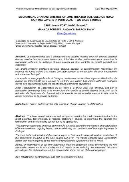
Premier Symposium Méditerranéen <strong>de</strong> Géoengineering «SMGE09» Alger 20 et 21 juin 2009<br />
MECHANICAL CHARACTERISTICS OF LIME TREATED SOIL USED ON ROAD<br />
CAPPING LAYERS IN PORTUGAL - TWO CASE STUDIES<br />
CRUZ. Joana 1 FORTUNATO. Eduardo 2,1<br />
VIANA DA FONSECA. António 1 & BARROS. Paulo 3<br />
jfscruz@gmail.com<br />
1 Facul<strong>da</strong><strong>de</strong> <strong>de</strong> Engenharia <strong>da</strong> Universi<strong>da</strong><strong>de</strong> do Porto (FEUP), Portugal<br />
2 Laboratório Nacional <strong>de</strong> Engenharia Civil (LNEC), Lisboa, Portugal<br />
3 Brisa Engenharia e Gestão (BEG), Lisboa, Portugal<br />
Résumé : Le traitement <strong>de</strong>s sols à la chaux est une solution reconnu pour son énorme potentiel<br />
<strong>da</strong>ns la construction <strong>de</strong>s routes. Néanmoins, il faut <strong>de</strong>s étu<strong>de</strong>s préliminaires pour déterminer la<br />
formulation optimum du mélange et pour assurer un strict contrôle <strong>de</strong> qualité pen<strong>da</strong>nt son<br />
exécution.<br />
Cet article présente quelques résultats obtenus pen<strong>da</strong>nt la caractérisation mécanique <strong>de</strong><br />
couches <strong>de</strong> forme traités à la chaux exécutée pen<strong>da</strong>nt la construction <strong>de</strong> <strong>de</strong>ux importantes<br />
autoroutes au Portugal.<br />
Les essais <strong>de</strong> charge performés et l’analyse postérieure <strong>de</strong>s résultats a permis l’évaluation du<br />
module <strong>de</strong> déformabilité <strong>de</strong> la couche <strong>de</strong> sol traité à la chaux. Les valeurs obtenues sont plus<br />
élevés que ceux stipulés <strong>da</strong>ns les spécifications techniques applicables.<br />
Ainsi, l’optimisation <strong>de</strong> l’application du sol traité à la chaux peut être effectué, soit par la<br />
formulation du mélange basé <strong>da</strong>ns les résultats <strong>de</strong> contrôle <strong>de</strong> qualité obtenus in situ, soit par la<br />
réduction <strong>de</strong> l’épaisseur du chaussé selon le module <strong>de</strong> déformabilité mesuré in situ <strong>da</strong>ns le<br />
niveau supérieur <strong>de</strong> la couche <strong>de</strong> forme.<br />
Mots-Clefs : Chaux, traitement <strong>de</strong>s sols, essais <strong>de</strong> charge, module <strong>de</strong> déformation<br />
Abstract : The lime treated soils is a well recognized solution for road construction due to its<br />
great potential. Nevertheless, it requires preliminary studies to <strong>de</strong>termine the optimal mix<br />
formulation and a strict quality control during its application.<br />
This paper presents and analyses some results obtained during the mechanical characterization<br />
of lime treated road capping layers, performed during the construction of two major highways in<br />
Portugal.<br />
The load tests performed and the back analysis of their results have allowed an evaluation of<br />
the <strong>de</strong>formation modulus of the lime treated soil layer. The values obtained were significantly<br />
higher than those required by the technical specifications applicable to these works.<br />
Hence, an optimization of soil lime application might be performed, either by changing the mix<br />
formulation based on in situ quality control results or by reducing the pavement thickness<br />
according to the <strong>de</strong>formation modulus measured in situ at the top of the capping layer.<br />
Key-Words: lime, soil treatment, load test, <strong>de</strong>formation modulus
Premier Symposium Méditerranéen <strong>de</strong> Géoengineering «SMGE09» Alger 20 et 21 juin 2009<br />
1. Introduction<br />
The lime treatment of soils is one of the ol<strong>de</strong>st techniques used (more than 5000 years old).<br />
In<strong>de</strong>ed, even before the Romans, 2000 years ago, other peoples were already acquainted with<br />
that procedure. For instance, Shersi pyramids in Tibet were built with clay and lime compacted<br />
mixtures. Also, throughout the years, in China and India, lime treatment was used in various<br />
ways (Anca<strong>de</strong>, 1997).<br />
Presently, the lime potential in reducing the water content and the plasticity of soils is well<br />
recognized and, therefore, its application in soil mixtures, namely within the framework of<br />
geotechnical works, is normally taken into account in technical specifications.<br />
These mixtures have also been often used to improve the mechanical characteristics<br />
(<strong>de</strong>formability and strength) of compacted soils, particularly soils that, due their significant<br />
amount of fines, are usually discar<strong>de</strong>d, both in fills and in the substructure of transportation<br />
infra-structures, roads or railways. This aspect is very important, because the consequences of<br />
unbalanced earth works (embankments and excavation/cuttings) are <strong>de</strong>cisive, in terms of<br />
economic and environmental costs.<br />
Nevertheless, the lack of knowledge of the long term performances of these mixtures, together<br />
with the specific equipment <strong>de</strong>mands, the insufficient knowledge about the application<br />
techniques and, sometimes, the lack of an a<strong>de</strong>quate cost-benefit analysis, have placed major<br />
obstacles to accepting the use of such treatment in Portugal. Therefore, its use has not been<br />
systematically adopted. In fact, apart from the works indicated in this paper, regarding highways<br />
A2 (subsection Almodôvar – São Bartolomeu <strong>de</strong> Messines) and A10 (subsection Arru<strong>da</strong> dos<br />
Vinhos – IC11), which were carried out by the Brisa, SA in 2001 and 2005, respectively, the<br />
lime treatment of soils has only been used in a very few works. Furthermore, special reference<br />
is ma<strong>de</strong> to the works studied by Neves (1993), regarding the construction of the “North-South<br />
Axle Road (subsection Telheiras - Sete Rios)” and the “Lisbon Inner Ring Road – CRIL”<br />
(subsection Alto do Duque – Buraca), as well as to the earthworks inclu<strong>de</strong>d in the<br />
mo<strong>de</strong>rnization of the North Line (subsections Azambuja - Vale <strong>de</strong> Santarém and Entroncamento<br />
Norte – Albergaria tunnel), which were performed in 2003 by the railway administration.<br />
Nevertheless, this scenario has been significantly changing in construction pratice. In fact, the<br />
technical and environmental requirements placed by the new transportation infra-structures, in<br />
particular the high speed railway network and the new Lisbon airport, is most likely to promote<br />
the use of the lime treatment of soils, as an alternative to their replacement.<br />
2. Case Studies<br />
This paper presents various studies related with the lime treatment of embankment and capping<br />
layers of pavements. Those studies concern two major roads constructed in Portugal: highways<br />
A2 and A10.<br />
The 240 km long highway A2, constructed in 2002, is the main link between Lisbon and Algarve<br />
project has taken into account the possibility of using lime treated soils on the pavement<br />
capping layer. The insufficient amount of appropriate soils to be used in capping layer within an<br />
acceptable distance was the main reason for adopting the lime treatment of soils.<br />
Highway A10 is a multi-purpose road aimed for those traveling from the Central and the West<br />
region of Lisbon towards the North of the country. It also serves those traveling from the West<br />
central part and from the north of Portugal down to Algarve, thus avoiding passing through<br />
Lisbon. The lay-out solution which was <strong>de</strong>veloped for the section of highway A10 led to a<br />
significant volume of excavations and embankments. Furthermore, it required the use of borrow<br />
materials with appropriate characteristics and in sufficient quantities, which were unavailable<br />
within acceptable distances. These factors have led to the solution of treating soils for the<br />
construction of embankments.<br />
Quicklime was the bin<strong>de</strong>r used in both works. Table 1 indicates the lime properties. In<br />
accor<strong>da</strong>nce with the specifications of the Portuguese Stan<strong>da</strong>rd NP EN 459-1 (2002), this lime is<br />
classified as CL90-Q.
Premier Symposium Méditerranéen <strong>de</strong> Géoengineering «SMGE09» Alger 20 et 21 juin 2009<br />
Table 1. Lime characteristics<br />
Properties<br />
Values<br />
CO 2 ≤ 3.5%<br />
CaO ≥ 92%<br />
SiO 2 ≤ 0.3%<br />
S ≤ 0.3%<br />
Retained on sieve #2.0 mm < 5%<br />
Bulk <strong>de</strong>nsity ≈ 1.0<br />
3. Study of the Mechanical Caracteristics After Treatment<br />
3.1. General aspects<br />
The quality control during the execution of earthworks and the evaluation of the bearing<br />
capacity of platforms, within the framework of transportation infra-structures, can be based on<br />
the <strong>de</strong>finition of minimum values of the <strong>de</strong>formation modulus measured at the top of the layers<br />
by means of non-<strong>de</strong>structive load tests. Despite the possibility of the imposed load and the<br />
associated response being rather different from those actually obtained during the passage of<br />
vehicles, the in situ characterization resulting from that class of tests has been proving to be<br />
very useful and reliable for assessing the different structural layers.<br />
3.2. Numerical mo<strong>de</strong>ling of the load test<br />
Based on the <strong>de</strong>flections obtained from falling weight <strong>de</strong>flectometer (FWD) load tests, it was<br />
possible to <strong>de</strong>termine the equivalent <strong>de</strong>formation modulus. Even more, it was possible to<br />
<strong>de</strong>termine the values of the <strong>de</strong>formation modulus of the different layers, by employing a<br />
numerical mo<strong>de</strong>l using the finite element method (FEM), by means of mo<strong>de</strong>ling in axysymmetric<br />
conditions. Using the commercial software Plaxis ® , it was possible to mo<strong>de</strong>l the load test on a<br />
linear elastic stratified medium. In an iterative way, <strong>de</strong>formation modulus of the different layers<br />
were changed as to converge the calculated <strong>de</strong>flection curves with those obtained in situ with<br />
the FWD.<br />
3.2.1 Highway A2<br />
The upper part (25 to 30 cm) of the capping layer (40 to 45 cm) was lime treated. Thus, two<br />
structures were consi<strong>de</strong>red for the load test mo<strong>de</strong>ling (Figure 1).<br />
Figure 1. Structures consi<strong>de</strong>red for the load test mo<strong>de</strong>ling (A2).<br />
Falling weight <strong>de</strong>flectometer tests<br />
In each FWD test point, three impacts were performed on a 30 cm diameter plate load,<br />
corresponding to 20, 30 and 45 kN. The <strong>de</strong>flection transducers (geophones) were placed at the<br />
following distances (in cm) from the load plate centre: 0 (Df1); 30 (Df2); 45 (Df3); 60 (Df4); 90<br />
(Df5); 120 (Df6); 150 (Df7); 180 (Df8) e 210 (Df9).<br />
Figure 2 presents the finite element mesh used for structure 1, taking into account the boun<strong>da</strong>ry<br />
conditions and the different layers of the pavement substructure. All the finite element meshes<br />
consi<strong>de</strong>red in the other cases presented in this paper are i<strong>de</strong>ntical, except for the thicknesses of<br />
the different layers.
Premier Symposium Méditerranéen <strong>de</strong> Géoengineering «SMGE09» Alger 20 et 21 juin 2009<br />
Figure 2. Mesh used – structure 1 (A2).<br />
Calculation of the <strong>de</strong>formation modulus based on the numerical analysis<br />
First of all, it should be highlighted that a significant variability was obtained in the in situ<br />
displacements measured by geophones on the different test points. The calculation of the<br />
<strong>de</strong>formation modulus was done based on results obtained from the first height impact, i.e., for a<br />
peak load of approximately 20 kN.<br />
Initially, an attempt was ma<strong>de</strong> to find the <strong>de</strong>formation modulus of both the subgra<strong>de</strong> and the<br />
bottom capping layer, in or<strong>de</strong>r to <strong>de</strong>termine the outer part of the <strong>de</strong>flection basin (the most<br />
distant from the load application place). For this purpose, the <strong>de</strong>formation modulus of the<br />
treated soils was fixed on 200 MPa and the <strong>de</strong>formation modulus of the subgra<strong>de</strong> and of the<br />
untreated soil (indicated as “soil”) varied as showed in Table 2.<br />
Table 2. Hypotheses consi<strong>de</strong>red for the <strong>de</strong>formation modulus of the subgra<strong>de</strong> and untreated soil.<br />
E treated<br />
Deflections [μm]<br />
E soil E<br />
Hypothesis<br />
subgra<strong>de</strong><br />
soil<br />
Df1 Df2 Df3 Df4 Df5 Df6 Df7 Df8 Df9<br />
[MPa] 0 30 45 60 90 120 150 180 210<br />
1 50 80 434 218 144 99 55 35 25 19 16<br />
2 60 80 423 210 140 98 55 36 26 20 16<br />
3 80 100 372 170 111 77 44 29 21 16 13<br />
4 80 120 348 149 94 64 35 23 17 13 10<br />
200<br />
5 60 140 346 143 85 55 29 19 14 11 9<br />
6 80 160 317 122 72 47 26 17 13 10 8<br />
7 100 170 300 111 66 43 24 16 12 9 7<br />
8<br />
120 170 292 107 64 43 25 17 12 9 7<br />
The minimum and maximum <strong>de</strong>flection basins indicated in Figure 3, correspond to the minimum<br />
and maximum displacements measured by geophones. Hence, the minimum basin corresponds<br />
to the structure with the best mechanical characteristics and the maximum basin corresponds to<br />
the structure with the worst mechanical characteristics.
Premier Symposium Méditerranéen <strong>de</strong> Géoengineering «SMGE09» Alger 20 et 21 juin 2009<br />
Figure 3. Deflection basins obtained for the hypotheses consi<strong>de</strong>red for subgra<strong>de</strong> and soil <strong>de</strong>formation<br />
modulus.<br />
Based on this analysis, hypothesis 5 was chosen, because it was assumed to represent an<br />
average curve. As consequence, a subgra<strong>de</strong> with a <strong>de</strong>formation modulus of about 140 MPa,<br />
and a untreated soil with a modulus of 60 MPa, were consi<strong>de</strong>red.<br />
A parametric study was then performed, in which the following calculation conditions were<br />
consi<strong>de</strong>red:<br />
- subgra<strong>de</strong> with a <strong>de</strong>formation modulus of 140 MPa;<br />
- untreated soil with a <strong>de</strong>formation modulus of 60 MPa; and<br />
- lime treated soil layer with a varying the <strong>de</strong>formation modulus on 120, 200, 400 and 600 MPa.<br />
The calculations have taken into account this range of values for the different structures,<br />
allowing to <strong>de</strong>termine the <strong>de</strong>flections presented at the Table 3 and Table 4.<br />
Table 3. Deflections obtained with PLAXIS ® for different hypotheses (structure 1)<br />
Deflections [μm]<br />
E soil E subgra<strong>de</strong><br />
soil<br />
Df1 Df2 Df3 Df4 Df5 Df6 Df7 Df8 Df9<br />
[MPa] 0 30 45 60 90 120 150 180 210<br />
120 458 149 81 51 28 19 14 11 9<br />
200 346 143 85 55 29 19 14 11 9<br />
60 140<br />
400 247 131 87 59 31 20 14 11 9<br />
600<br />
206 123 86 61 33 20 14 11 9<br />
E treated<br />
Table 4. Deflections obtained with PLAXIS ® for different hypotheses (structure 2)<br />
Deflections [μm]<br />
E soil E subgra<strong>de</strong><br />
soil<br />
Df1 Df2 Df3 Df4 Df5 Df6 Df7 Df8 Df9<br />
[MPa] 0 30 45 60 90 120 150 180 210<br />
120 452 149 84 53 28 19 14 11 9<br />
200 332 138 86 57 30 20 14 11 9<br />
60 140<br />
400 229 122 85 60 33 21 14 11 9<br />
600<br />
188 112 83 61 35 21 15 11 9<br />
E treated
Premier Symposium Méditerranéen <strong>de</strong> Géoengineering «SMGE09» Alger 20 et 21 juin 2009<br />
From the analysis of the <strong>de</strong>flections obtained on structures 1 and 2, it was possible to observe,<br />
as expected, that the <strong>de</strong>flections on structure 1 are higher, when the treated soil layer is thinner.<br />
Nevertheless, the difference is not significant, and, therefore, the interpretation was done using<br />
only structure 1, i.e., the most unfavorable one.<br />
Figure 4 <strong>de</strong>picts the <strong>de</strong>flection basin of structure 1, taking into account the various hypotheses<br />
consi<strong>de</strong>red. Furthermore, the normalised <strong>de</strong>flections for 20 kN load of FWD tests performed in<br />
situ on the treated soil (mixture with 4% of lime) are also represented (Pk26525 and Pk26550).<br />
Figure 4. Deflections obtained with PLAXIS ® for different hypotheses (structure 1) and normalized<br />
<strong>de</strong>flections for 20 kN load (layer with 4% lime)<br />
The comparison of the different <strong>de</strong>flection basins – measured in situ and obtained with<br />
PLAXIS® – allowed to conclu<strong>de</strong> that the best fit corresponds to <strong>de</strong>formation modulus values of<br />
lime treated soils of about 200 to 400 MPa.<br />
The equivalent <strong>de</strong>formation modulus calculated using the maximum <strong>de</strong>flection obtained at the<br />
Pk26550 test (375 μm) is 170 MPa. This value is higher than the one specified in the <strong>de</strong>sign.<br />
3.2.2 Highway A10<br />
The <strong>de</strong>sign of this highway specifies that the pavement substructure should present<br />
characteristics that will ensure that the <strong>de</strong>formation modulus at the top of the capping layer<br />
would be higher than 120 MPa at long term.<br />
In a first stage, a test section was constructed in or<strong>de</strong>r to confirm if the substructure <strong>de</strong>formation<br />
characteristics required in the <strong>de</strong>sign could be achieved, and also to assess the effectiveness of<br />
the equipment used and to verify the homogeneity of the work performed. In a second stage,<br />
two evaluation campaigns were performed on previously completed work sections.<br />
As a result, and in accor<strong>da</strong>nce with the layout presented in Figure 5, the pavement structure is<br />
expected to be as follows:<br />
- the bottom capping layer of lime treated soils (LT1) with a 40 cm thickness;<br />
- the top capping layer consist of two layers: a 20 cm layer of lime treated soils (LT2) overlaid by<br />
a 20 cm layer of a well gra<strong>de</strong>d crushed aggregate (ABGC).
Premier Symposium Méditerranéen <strong>de</strong> Géoengineering «SMGE09» Alger 20 et 21 juin 2009<br />
The subgra<strong>de</strong> was consi<strong>de</strong>red to be divi<strong>de</strong>d into two separate layers, a top layer with a 60 cm<br />
thickness and a bottom layer (SubR) more rigid and semi-infinite in <strong>de</strong>pth as often adopted for<br />
mo<strong>de</strong>ling purposes.<br />
Figure 5. Pavement structure (A10).<br />
Falling weight <strong>de</strong>flectometer tests<br />
The load tests using the falling weight <strong>de</strong>flectometer (FWD) were performed on a well i<strong>de</strong>ntified<br />
section, on the top of the capping layer. The configuration adopted for the FWD as follows:<br />
- 20 kN load applied on a 45 cm diameter plate;<br />
- <strong>de</strong>flection transducers placed at the following distances (in cm) from the load plate center: 0<br />
(Df1); 30 (Df2); 45 (Df3); 60 (Df4); 90 (Df5); 120 (Df6); 150 (Df7); 180 (Df8) and 210 (Df9).<br />
Calculation of the <strong>de</strong>formation modulus based on a numerical analysis<br />
The <strong>de</strong>formation of the different substructure layers were estimated using the results of the<br />
FWD load tests, the thickness of the layers and the characteristics of the materials.<br />
Nevertheless, a great variability in results was observed on campaigns performed both on the<br />
test section and during the construction of the highway.<br />
The values of the <strong>de</strong>formation modulus (E) consi<strong>de</strong>red are indicated in Table 5, while the<br />
corresponding <strong>de</strong>flections obtained through numerical mo<strong>de</strong>ling are indicated in Table 6.<br />
Table 5. Hypotheses consi<strong>de</strong>red in the numerical mo<strong>de</strong>ling.<br />
E [MPa]<br />
Hypotheses<br />
LT1 Top of<br />
ABGC and the Subgra<strong>de</strong><br />
LT2 Subgra<strong>de</strong><br />
1 280 550 55 810<br />
2 220 350 50 750<br />
3 300 600 100 800<br />
4 600 600 100 800<br />
5 300 400 100 800<br />
6 150 300 100 800<br />
7 300 600 200 800
Premier Symposium Méditerranéen <strong>de</strong> Géoengineering «SMGE09» Alger 20 et 21 juin 2009<br />
Table 6. Deflections obtained with PLAXIS ® .<br />
Hypotheses<br />
Deflections [μm]<br />
Df 1 Df 2 Df 3 Df 4 Df 5 Df 6 Df 7 Df 8 Df 9<br />
1 118 66 44 35 24 16 10 6 3<br />
2 156 88 57 44 27 17 10 6 3<br />
3 101 53 34 26 17 11 7 5 3<br />
4 76 49 33 26 17 11 7 5 3<br />
5 90 60 40 30 18 11 7 4 3<br />
6 177 83 45 32 18 10 6 4 3<br />
7 92 45 26 19 12 8 6 4 3<br />
Figure 6 shows the <strong>de</strong>flection basins obtained taking into account the various hypotheses. The<br />
same figure also shows the <strong>de</strong>flections of three FWD tests (20 kN load) performed in situ during<br />
one of the campaigns (Pk3+750, Pk3+875, Pk3+975).<br />
Figure 6. Deflection basins obtained through numerical mo<strong>de</strong>ling and in situ test campaign.<br />
From the analysis of results, it is possible to conclu<strong>de</strong> that the layers of lime treated soil can<br />
present values of the <strong>de</strong>formation modulus ranging from 300 to 600 MPa. The equivalent<br />
<strong>de</strong>formation modulus calculated using the maximum <strong>de</strong>flection obtained at the Pk3+750 test<br />
(210 μm) is 200 MPa. This value is higher than the one specified in the <strong>de</strong>sign (120 MPa).<br />
4. CONCLUSIONS<br />
The use of lime treated soils during the construction of the substructure of road pavements is an<br />
ancient technique, yet not common in transportation infrastructure construction practice in<br />
Portugal. Nevertheless, during the construction of the two highways that technical solution was<br />
applied. The falling weight <strong>de</strong>flectometer equipment was used to perform in situ tests.<br />
The use of numerical analysis of obtained results allowed to estimate the values of the<br />
<strong>de</strong>formation modulus of the lime treated capping layer. It was observed that the values of the<br />
<strong>de</strong>formation modulus obtained are higher than the pre-established ones.
Premier Symposium Méditerranéen <strong>de</strong> Géoengineering «SMGE09» Alger 20 et 21 juin 2009<br />
Within certain limits, higher lime percentages are expected to provi<strong>de</strong> layers with better<br />
performance, yet leading to expensive structures. Consequently, the lime content must be<br />
<strong>de</strong>termined in or<strong>de</strong>r to reach the pre-established <strong>de</strong>formation modulus value. Only this<br />
procedure enables to reach a technical and economical solution that can be compared with<br />
traditional ones.<br />
The quality control during the construction of stabilized layers by performance based tests<br />
should be a current practice leading to a consistent evaluation of the a<strong>de</strong>quate lime dosages to<br />
be used.<br />
5. ACKNOWLEDGEMENTS<br />
This work is integrated within the framework of a research work for obtaining the MSc <strong>de</strong>gree in<br />
Civil Engineering and it was performed un<strong>de</strong>r a protocol for co-operation established between<br />
the Instituto <strong>da</strong> Construção of Facul<strong>da</strong><strong>de</strong> <strong>de</strong> Engenharia <strong>da</strong> Universi<strong>da</strong><strong>de</strong> do Porto (IC-FEUP)<br />
and the company LUSICAL Companhia Lusitana <strong>de</strong> Cal, SA - Société Balthazard & Cotte,<br />
member of the Lhoist Group with the purpose of conducting the studies intitled “Estudos <strong>de</strong><br />
solos portugueses tratados com cal com vista à sua aplicação nas infra-estruturas <strong>de</strong><br />
transporte”. Therefore, acknowledgements are due to Mr Paulo Correia and Mr Mário Marques,<br />
for their kind support.<br />
Furthermore, thanks are also due to the company Brisa for providing all the necessary<br />
elements, which were essential for carrying out the study and the comparison of results<br />
obtained in the numerical simulation with those observed in situ.<br />
6. REFERENCES<br />
Anca<strong>de</strong> (1997). Asociación Nacional <strong>de</strong> Fabricantes <strong>de</strong> Cales y Derivados <strong>de</strong> España - Manual <strong>de</strong><br />
estabilización <strong>de</strong> suelos con cal. Madrid, España.<br />
CAeMD (2005). Publicações e Projectos <strong>de</strong> Engenharia, L<strong>da</strong> - A10 - Auto Estra<strong>da</strong><br />
Bucelas/Carregado/A13. Sublanço Arru<strong>da</strong> dos Vinhos/IC11. Nota Técnica: Avaliação <strong>da</strong>s<br />
características <strong>de</strong> <strong>de</strong>formabili<strong>da</strong><strong>de</strong> do leito <strong>de</strong> pavimento. Portugal.<br />
Neves, J. M. C. (1993). Estabilização <strong>de</strong> Solos com Cal - Estudos e Aplicações Rodoviárias. MSc thesis.<br />
Universi<strong>da</strong><strong>de</strong> Nova <strong>de</strong> Lisboa, Portugal.<br />
NP EN 459-1 (2002) Cal <strong>de</strong> Construção: Definições, especificações e critérios <strong>de</strong> conformi<strong>da</strong><strong>de</strong>.<br />
Portuguese Stan<strong>da</strong>rd. Instituto Português <strong>da</strong> Quali<strong>da</strong><strong>de</strong>.