L10 - blain hydraulics Gmbh
L10 - blain hydraulics Gmbh
L10 - blain hydraulics Gmbh

You also want an ePaper? Increase the reach of your titles
YUMPU automatically turns print PDFs into web optimized ePapers that Google loves.
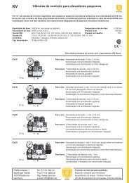
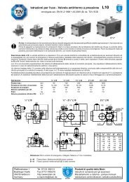
Pressure Lock Valve<br />
Certifi ed EN 81-2 (A3)<br />
TÜV SÜD<br />
½“ ¾“<br />
1 ½“ 2“<br />
2 ½“<br />
GB<br />
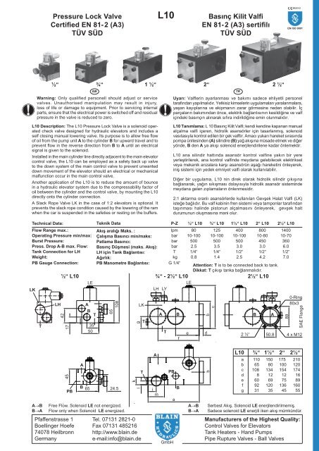
Warning: Only qualified personell should adjust or service<br />
valves. Unauthorised manipulation may result in injury,<br />
loss of life or damage to equipment. Prior to servicing internal<br />
parts, ensure that the electrical power is switched off and residual<br />
pressure in the valve is reduced to zero.<br />
<strong>L10</strong> Description: The <strong>L10</strong> Pressure Lock Valve is a solenoid operated<br />
check valve designed for hydraulic elevators and includes a<br />
self closing manual lowering valve. Its purpose is to allow free fl ow<br />
of oil from the pump unit A to the cylinder B for upward travel and to<br />
prevent fl ow in the reverse direction from B to A until an electrical<br />
signal is given to the solenoid.<br />
Installed in the main cylinder line directly adjacent to the main elevator<br />
control valve, the <strong>L10</strong> can be employed as a safety back up valve<br />
to the down system of the main control valve to prevent unwanted<br />
down movement of the elevator should an electrical or mechanical<br />
malfunction occur in the main control valve.<br />
Another application of the <strong>L10</strong> is to reduce the amount of bounce<br />
in a hydraulic elevator system due to the compressability factor of<br />
oil between the cylinder and the control valve, by mounting the <strong>L10</strong><br />
directly onto the cylinder connection.<br />
A Slack Rope Valve LK in the case of 1:2 elevators is optional. It<br />
prevents the slack rope condition caused by the lowering of the ram<br />
when the car is suspended in the safeties or resting on the buffers.<br />
Flow Range max.: � ��������������������<br />
lpm 80 125 400 800 1400<br />
Operating Pressure min/max: � ������������������������� bar 10-100 10-100 10-100 10-80 10-70<br />
Burst Pressure: � ����������������<br />
bar 500 500 500 450 360<br />
Press. Drop A-B max. Flow: � ���������������������������� bar 2.5 3.5 3.0 3.0 6.0<br />
Tank Connection for LH � ������������������������<br />
T 1/4“ 1/4“ 1/2“ 1/2“ 1/2“<br />
Weight: � ��������<br />
kg 0.8 1.4 2.5 4.2 7.0<br />
PB Gauge Connection: � ������������������������<br />
G 1/4“<br />
Attention: T is to be connected back to tank.<br />
�������������������������������������<br />
½“ <strong>L10</strong> ¾“ - 2½“ <strong>L10</strong> 2½“ <strong>L10</strong><br />
LE<br />
LE<br />
LK<br />
LH LY<br />
T<br />
LH<br />
42<br />
17<br />
45<br />
PB<br />
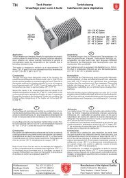
A�B Free Flow. Solenoid LE not energized.<br />
B�A Flow only when Solenoid LE energized.<br />
A<br />
A<br />
B<br />
B 65<br />
65<br />
108<br />
24.5<br />
k<br />
g<br />
l<br />
Pfaffenstrasse 1 Tel. 07131 2821-0<br />
Boellinger Hoefe Fax 07131 485216<br />
74078 Heilbronn http://www.<strong>blain</strong>.de<br />
Germany e-mail:info@<strong>blain</strong>.de<br />
T<br />
LK<br />
T<br />
T<br />
A<br />
i<br />
m<br />
<strong>L10</strong><br />
Technical Data: � �����������<br />
P-Z ½“ <strong>L10</strong> ¾“ <strong>L10</strong> 1½“ <strong>L10</strong> 2“ <strong>L10</strong> 2½“ <strong>L10</strong><br />
35<br />
50<br />
A B<br />
T<br />
PB<br />
GmbH<br />
a<br />
f<br />
B<br />
e<br />
������������������<br />
EN 81-2 (A3) sertifi lı<br />
TÜV SÜD<br />
b<br />
d<br />
b<br />
c<br />
TR<br />
B A<br />
89<br />
EN 81-2<br />
EN ISO 9001<br />
������� ���������� ������������ ��� ������� ������� ���������� ���������<br />
�������������������������������������������������������������������������<br />
��������������������������������������������������������������� ���<br />
�����������������������������������������������������������������������<br />
�����������������������������������������������������������������<br />
���������������������������������������������������������������������<br />
�������� ������ �������� ��������� ����������� ����� ������������� ���������<br />
���������������������������������������������������������������������������<br />
����������������������������������������������������������������������<br />
��������������������������������������������������������������������<br />
���� ���� ��������� ��������� �������� �������� �������� ������ ���� �����<br />
����������������������������������������������������������������������<br />
�������������������������������������������������������������������<br />
������������������������������������������������������������<br />
������ ���� ���������� ���� ���� ������ ������� ��������� ��������� ���������<br />
��������������������������������������������������������������������<br />
����������������������������������������<br />
�������������������������������������������������������������������<br />
������������������������������������������������������������������������<br />
���������� �������� ��������� ������������ ����������� � ������� �����<br />
�������������������������������<br />
0-Ring<br />
80x3<br />
SAE Flange<br />
2 ½“ 50.8 4 x M12<br />
<strong>L10</strong> ¾“ 1½“ 2“ 2½“<br />
a 110 150 175 210<br />
b 65 80 100 120<br />
c 108 134 154 174<br />
d 8 12 12 16<br />
e 60 69 75 89<br />
f 92 120 136 160<br />
g 31 35 45 55<br />
���� ����������������������������������������������<br />
���� ������������������������������������������������<br />
Manufacturers of the Highest Quality:<br />
Control Valves for Elevators<br />
Tank Heaters - Hand Pumps<br />
Pipe Rupture Valves - Ball Valves
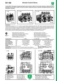
Rest Position: The condition of rest of the <strong>L10</strong> valve is with the<br />
solenoid LE de-energized and the main fl ow guide LV closed, preventing<br />
fl ow from cylinder to tank.<br />
Up Travel: During up travel with the pump running, oil fl ows through<br />
port A, through fl ow guide LV and out through port B to the main<br />
cylinder. Solenoid LE is not energized.<br />
Down Travel: For the elevator to travel downwards, in addition to the<br />
down solenoids C and D of the EV 100 control valve, solenoid LE of<br />
the Pressure Lock Valve is energized causing the fl ow guide LV to<br />
open and allowing oil from the cylinder to fl ow in the direction, port B<br />
to port A, of the Pressure Lock Valve and through the EV 100 control<br />
valve to tank.<br />
To slow down the elevator, solenoid C of the EV 100 is de-energized.<br />
Only upon completion of down levelling, is the solenoid LE of the <strong>L10</strong><br />
together with solenoid D of the EV 100 de-energized, causing both fl ow<br />
guides, X of the EV 100 and LV of the <strong>L10</strong> to close.<br />
Manual Down: In the event of an emergency, self closing Manual Down<br />
LH can be opened to pilot operated adjustable lowering speed valve<br />
LY to lower the elevator. In the case of the operation of the safeties<br />
in a 2:1 hydraulic lift system where the weight of the car is no longer<br />
carried by the ropes, the optional Slack Rope Valve LK prevents the<br />
ram being lowered when the manual lowering valve is opened which<br />
would cause a slack rope condition.<br />
Adjustments<br />
Manual Down Speed LY (3/4“, 1½“, 2“ and 2½“ valves): ‘In‘<br />
(clockwise) provides a slower, ‘out‘ a faster down lowering speed.<br />
Slack Rope Valve LK: The LK is adjusted with a 3 mm Allan Key by<br />
turning the screw LK ‘in‘ for higher pressure and ‘out‘ for lower pressure.<br />
With LK turned all the way ‘in‘, then half a turn back out, the<br />
unloaded car should descend when the LE solenoid alone is energised.<br />
Should the car not descend, LK must be backed off until the car just<br />
begins to descend, then backed off a further half turn to ensure that<br />
with cold oil, the car can be lowered as required.<br />
Hydraulic Circuit<br />
�������������<br />
Pressure Lock Valve<br />
GB<br />
No. Parts List<br />
� ���� �������������<br />
LF Flange<br />
� ��� �����<br />
LFO 0-Ring- Flange<br />
� ���� ������<br />
LB Ball<br />
� ��� ����<br />
LVF Spring - Flow Guide<br />
� ���� �����������������<br />
LFG Flow Guide<br />
� ���� �������������<br />
LVO Seal - Flow Guide<br />
� ���� ������������������<br />
LVB Body - Flow Guide<br />
� ���� ��������������������<br />
LUO O-Ring - Flow Guide<br />
� ���� ��������������������<br />
LH Manual Down - Self Closing � ��� ����������������<br />
LY Manual Down Speed Adjuster � ��� ������������������������<br />
HO Seal - Manual Low. (5.28x1.78) � ��� �������������������������������<br />
MM Nut Solenoid<br />
� ��� �����<br />
M Coil Solenoid (indicate voltage) � �� �����<br />
MD Emergency Dual Power Coil � ��� ���������������������<br />
DR Tube - Solenoid<br />
� ��� ������������<br />
MO 0-Ring Solenoid<br />
� ��� ���������������<br />
DF Spring Solenoid<br />
� ��� ������������<br />
DN Needle Solenoid<br />
� ��� �������������<br />
DK Core Solenoid<br />
� ��� �����������������<br />
DG Seat Housing (with screen) � ��� ����������������<br />
DS Seat Solenoid<br />
� ��� �������������<br />
PB<br />
B<br />
T<br />
LK LH<br />
LY<br />
LV<br />
LE<br />
<strong>L10</strong> EV 100<br />
A Z<br />
<strong>L10</strong><br />
Control Elements<br />
LV Check Valve<br />
LH Manual Lowering<br />
LK Slack Rope Valve (option)<br />
LE Solenoid<br />
PB Pressure Gauge<br />
LY Manual Down Speed<br />
Adjust. (not with 1/2“ <strong>L10</strong>)<br />
Connections<br />
A Control Valve Connection<br />
B Cylinder Side Connection<br />
T Tank Return Line<br />
LVO LVB LUO<br />
2 jan 12 BLAIN HYDRAULICS Designers and Builders of High Quality Valves for Hydraulic Elevators Printed in Germany<br />
LK<br />
HO<br />
LH<br />
������������������<br />
TR<br />
������������������������������������������������������������������<br />
�����������������������������������������������������������������������<br />
�������������������������������<br />
������� ��������� ������ ������� ������������ ������� �������� ����������<br />
������������������������������������������������������������������������<br />
���������������������������������������������������������������������<br />
���������������������������������������������������������������������<br />
��������������������������������������������������������������������������<br />
��������������������������������������������������������������������������<br />
����������������������������������������������������������������������<br />
������������<br />
�����������������������������������������������������������������������<br />
�����������������������������������������������������������������������<br />
��������������������������������������������������������������������������<br />
���������������������������������������������������������������������������<br />
�������������������<br />
�������������������������������������������������������������������<br />
��������������������������������������������������������������������������<br />
������������������������������������������������������������������������<br />
������������������������������������������������������������������������<br />
���������������������������������������������������������������������<br />
�����������������������������������������������������������������������<br />
�������������������������������<br />
�������<br />
���������������������3/4“, 1½“, 2“����2½“���������������������������������<br />
��������������������������������������������������������������������������<br />
�������������������������������������������������������������������<br />
������� ���������� ����� ������ ������ ��� ������ ���������� ����� ������� ������<br />
����������������������������������������������������������������������<br />
�����������������������������������������������������������������������<br />
�����������������������������������������������������������������������<br />
��������� ������������� ������ ������� ������ ��� ����������� ���� ������<br />
�������������������������������������������������������������������������<br />
���������������������<br />
�����������������<br />
��������������<br />
T<br />
LY<br />
LFG<br />
PB<br />
DR<br />
LVF<br />
LV<br />
<strong>L10</strong> 1 1/2“ - 2 1/2“<br />
Do not reduce G 1/2“ - Use 1/2“ tubing ( 18 x 1,5)<br />
G 1/2“������������������������1/2“������������������������<br />
LE<br />
������������������<br />
��� ��������<br />
��� ���������������������<br />
��� ����������������������������<br />
��� ���������<br />
��� ���������<br />
��� ����������������������<br />
� �1/2“��������������<br />
�����������<br />
�� �����������������������<br />
�� �������������������<br />
�� �����������������<br />
MM<br />
DK<br />
DF<br />
DN<br />
DG<br />
MO<br />
LB<br />
DS<br />
LF<br />
LFO