GENESIS STANDARD (GR) SERIES - HVAC Tech Support
GENESIS STANDARD (GR) SERIES - HVAC Tech Support
GENESIS STANDARD (GR) SERIES - HVAC Tech Support

You also want an ePaper? Increase the reach of your titles
YUMPU automatically turns print PDFs into web optimized ePapers that Google loves.
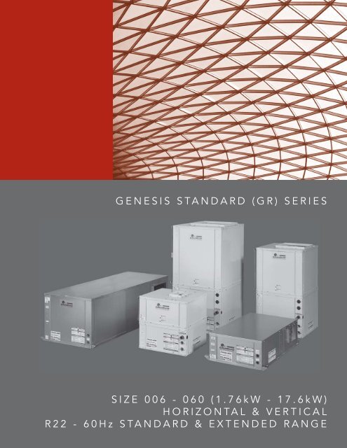
<strong>GENESIS</strong> <strong>STANDARD</strong> (<strong>GR</strong>) <strong>SERIES</strong><br />
SIZE 006 - 060 (1.76kW - 17.6kW)<br />
HORIZONTAL & VERTICAL<br />
R22 - 60Hz <strong>STANDARD</strong> & EXTENDED RANGE
<strong>GENESIS</strong> <strong>STANDARD</strong> (<strong>GR</strong>) <strong>SERIES</strong><br />
SIZE 006 - 060 (1.76kW - 17.6kW)<br />
HORIZONTAL & VERTICAL<br />
R22 - 60Hz <strong>STANDARD</strong> AND EXTENDED RANGE
THE SMART SOLUTION FOR ENERGY EFFICIENCY<br />
Genesis Standard (<strong>GR</strong>) Series<br />
Rev.: 05/23/07D<br />
THE <strong>GENESIS</strong> <strong>STANDARD</strong> (<strong>GR</strong>) <strong>SERIES</strong><br />
The <strong>GR</strong> series offers high efficiency, quiet operation<br />
with advanced features and application flexibility at<br />
competitive prices. <strong>GR</strong> series exceeds ASHRAE 90.1<br />
efficiencies, yet maintains small cabinet dimensions.<br />
Available in sizes 1/2 ton (1.76 kW) through 5 tons (17.6<br />
kW) with multiple vertical and horizontal cabinet options<br />
the <strong>GR</strong> series offers a wide range of units for most any<br />
installation. The <strong>GR</strong> has an extended range refrigerant<br />
circuit, capable of ground loop (geothermal) applications<br />
as well as water loop (boiler-tower) applications. Standard<br />
features are many. Microprocessor controls, galvanized<br />
steel cabinet, polyester powder coat paint (vertical units)<br />
and TXV refrigerant metering device are just some of the<br />
features of the flexible <strong>GR</strong> series.<br />
ClimateMaster’s exclusive double isolation compressor<br />
mounting system makes the <strong>GR</strong> series the quietest unit<br />
on the market. Compressors are mounted on vibration<br />
isolation springs to a heavy gauge mounting plate,<br />
which is then isolated from the cabinet base with rubber<br />
grommets for maximized vibration/sound attenuation.<br />
Options such as e-coated air coil, DDC controls, internal<br />
pump and factory-installed water solenoid valves allow<br />
customized design solutions.<br />
The <strong>GR</strong> Series water-source heat pumps are designed to<br />
meet the challenges of today’s <strong>HVAC</strong> demands with a low<br />
cost/high value solution.<br />
UNIT FEATURES<br />
• Sizes 006 (1/2 ton, 1.76 kW) through 060 (5 tons, 17.6 kW)<br />
• Rotary, reciprocating and scroll compressors<br />
• Exceeds ASHRAE 90.1 efficiencies<br />
• Galvanized steel construction with polyester powder<br />
coat paint (vertical units)<br />
• Unique double isolation compressor mounting with<br />
vibration isolation springs for quiet operation<br />
• Insulated divider and separate compressor/air<br />
handler compartments<br />
• TXV metering device<br />
• Extended range (20 to 120°F, -6.7 to 48.9°C) operation<br />
• Microprocessor controls standard (optional DXM and/or<br />
DDC controls)<br />
• LonWorks, BACnet, Modbus and Johnson N2<br />
compatibility options for DDC controls<br />
• Field convertible discharge air arrangement for<br />
horizontal units<br />
• Factory-mounted hanger brackets for horizontal units<br />
• Internally trapped condensate drain line (vertical<br />
units only)<br />
• Flush securely-mounted corner post water connections<br />
(no backup wrench required)<br />
• Unit Performance Sentinel performance<br />
monitoring system<br />
• Eight Safeties Standard<br />
• Wide variety of options including e-coated air coils and<br />
internal pumps<br />
www.climatemaster.com<br />
<strong>GR</strong><br />
3
CLIMATEMASTER WATER-SOURCE HEAT PUMPS<br />
Genesis Standard (<strong>GR</strong>) Series<br />
Rev.: 05/23/07D<br />
Selection Procedure<br />
Reference Calculations<br />
Heating<br />
LWT = EWT -<br />
LAT = EAT +<br />
HE<br />
GPM x 500<br />
HC<br />
CFM x1.08<br />
HR<br />
LWT = EWT +<br />
GPM x 500<br />
LAT (DB) = EAT (DB) -<br />
Cooling<br />
SC<br />
CFM x1.08<br />
LC = TC - SC<br />
S/T = SC<br />
TC<br />
Legend and Glossary of Abbreviations<br />
BTUH = BTU( British Thermal Unit) per hour<br />
CFM = airfl ow, cubic feet/minute<br />
COP = coeffi cient of performance = BTUH output/BTUH input<br />
DB = dry bulb temperature (°F)<br />
EAT = entering air temperature, Fahrenheit (dry bulb/wet bulb)<br />
EER = energy effi ciency ratio = BTUH output/Watt input<br />
EPT = external pipe thread<br />
ESP = external static pressure (inches w.g.)<br />
EWT = entering water temperature<br />
GPM = water fl ow in U.S. gallons/minute<br />
HE = total heat of extraction, BTUH<br />
HC = air heating capacity, BTUH<br />
HR = total heat of rejection, BTUH<br />
HWC = hot water generator (desuperheater) capacity, Mbtuh<br />
IPT = internal pipe thread<br />
KW = total power unit input, kilowatts<br />
LAT = leaving air temperature, °F<br />
LC = latent cooling capacity, BTUH<br />
LWT = leaving water temperature, °F<br />
MBTUH = 1000 BTU per hour<br />
S/T = sensible to total cooling ratio<br />
SC = sensible cooling capacity, BTUH<br />
TC = total cooling capacity, BTUH<br />
WB = wet bulb temperature (°F)<br />
WPD = waterside pressure drop (psi & ft. of hd.)<br />
Conversion Table - to convert inch-pound (English) to SI (Metric)<br />
Air Flow Water Flow Ext Static Pressure Water Pressure Drop<br />
Airflow (L/s) = CFM x 0.472 Water Flow (L/s) = gpm x 0.0631 ESP (Pa) = ESP (in of wg) x 249 PD (kPa) = PD (ft of hd) x 2.99<br />
<strong>GR</strong><br />
4 ClimateMaster Water-Source Heating and Cooling Systems
THE SMART SOLUTION FOR ENERGY EFFICIENCY<br />
Genesis Standard (<strong>GR</strong>) Series<br />
Rev.: 05/23/07D<br />
Selection Procedure<br />
Step 1 Determine the actual heating and cooling loads at the<br />
desired dry bulb and wet bulb conditions.<br />
Step 2 Obtain the following de sign parameters: Entering water<br />
temperature, water flow rate in GPM, air flow in CFM,<br />
water fl ow pressure drop and design wet and dry bulb<br />
temperatures. Air flow CFM should be between 300 and<br />
450 CFM per ton. Unit water pressure drop should be<br />
kept as close as possible to each other to make water<br />
balancing easier. Go to the ap pro pri ate tables and find<br />
the proper indicated water flow and water tem per a ture.<br />
Step 3 Select a unit based on total and sensible cooling<br />
conditions. Select a unit which is closest to, but no<br />
larger than, the actual cooling load.<br />
Step 4 Enter tables at the design water fl ow and water<br />
temperature. Read the total and sensible cooling<br />
capacities (Note: interpolation is per mis si ble,<br />
ex trap o la tion is not).<br />
Step 5 Read the heating capacity. If it exceeds the design<br />
criteria it is acceptable. It is quite normal for Water-<br />
Source Heat Pumps to be selected on cooling capacity<br />
only since the heating output is usually greater than the<br />
cooling capacity.<br />
Step 6 Determine the correction factors associated with the<br />
variable factors of dry bulb and wet bulb (page 14).<br />
Corrected Total Cooling =<br />
tabulated total cooling x wet bulb correction.<br />
Corrected Sensible Cooling =<br />
tabulated sensible cooling x wet/dry bulb correction.<br />
Step 7 Compare the corrected capacities to the load<br />
re quire ments. Normally if the capacities are within 10%<br />
of the loads, the equipment is ac cept able. It is better<br />
to undersize than oversize, as undersizing improves<br />
humidity control, reduces sound levels and extends the<br />
life of the equip ment.<br />
Step 8 When completed, calculate water temperature rise<br />
and assess the selection. If the units selected are not<br />
within 10% of the load cal cu la tions, then review what<br />
effect chang ing the GPM, water temperature and/or air<br />
fl ow and air tem per a ture would have on the corrected<br />
capacities. If the desired capacity cannot be achieved,<br />
select the next larger or smaller unit and repeat the<br />
procedure. Remember, when in doubt, undersize<br />
slightly for best performance.<br />
Example Equipment Selection For Cool ing<br />
Step 1 Load Determination:<br />
Assume we have determined that the appropriate cooling load at the<br />
desired dry bulb 80°F and wet bulb 65°F con di tions is as follows:<br />
Total Cooling ...................................... 21,100 BTUH<br />
Sensible Cooling ................................. 15,900 BTUH<br />
Entering Air Temp .... 80°F Dry Bulb / 65°F Wet Bulb<br />
Step 2 Design Conditions:<br />
Similarly, we have also obtained the following design pa ram e ters:<br />
Entering Water Temp ....................................... 90°F<br />
Water Flow (Based upon 12°F rise in temp.) 4.5 GPM<br />
Air Flow .................................................... 700 CFM<br />
Step 3, 4 & 5 HP Selection:<br />
After making our preliminary selection (<strong>GR</strong>H024), we enter the<br />
tables at design water fl ow and water tem per a ture and read<br />
Total Cooling, Sens. Cooling and Heat of Rej. ca pac i ties:<br />
Total Cooling ....................................... 21,900 BTUH<br />
Sensible Cooling ................................. 16,700 BTUH<br />
Heat of Rejection ................................ 29,000 BTUH<br />
Step 6 & 7 Entering Air and Airfl ow Corrections:<br />
Next, we determine our correction factors.<br />
Table Ent Air Air Flow Cor rect ed<br />
Corrected Total Cooling = 21,900 x 0.971 x 0.985 = 20,946<br />
Corrected Sens Cooling = 16,700 x 1.070 x 0.938 = 16,761<br />
Corrected Heat of Reject = 29,000 x 0.969 x 0.983 = 27,623<br />
Step 8 Water Temperature Rise Calculation & As sess ment:<br />
Actual Temperature Rise<br />
12.3°F<br />
When we compare the Corrected Total Cooling and Corrected<br />
Sensible Cooling fi gures with our load re quire ments stated<br />
in Step 1, we discover that our selection is within +/- 10%<br />
of our sensible load requirement. Fur ther more, we see that<br />
our Cor rect ed Total Cooling fi gure is slightly undersized as<br />
recommended, when compared to the actual load.<br />
www.climatemaster.com<br />
<strong>GR</strong><br />
5
CLIMATEMASTER WATER-SOURCE HEAT PUMPS<br />
Genesis Standard (<strong>GR</strong>) Series<br />
Rev.: 05/23/07D<br />
<strong>GR</strong> Series Nomenclature<br />
Model Type<br />
<strong>GR</strong> = Genesis Reciprocating<br />
1 2 3 4 5 6 7 8 9 10 11 12 13 14 15<br />
G R H<br />
0 3 6 B G C<br />
3 0 C L B S<br />
Standard<br />
S = Standard<br />
Configuration<br />
H = Horizontal<br />
V = Vertical<br />
Unit Size<br />
006 (<strong>GR</strong>H Only)<br />
009<br />
012<br />
015<br />
019<br />
024<br />
030<br />
036<br />
042<br />
048<br />
060<br />
Revision Level<br />
A = Current Revision For Sizes 006 - 012 & 042 - 060<br />
B = Current Revision For 019 - 036<br />
C = Current Revision For 015<br />
Voltage<br />
G = 208-230/60/1<br />
E = 265/60/1<br />
H = 208-230/60/3<br />
F = 460/60/3<br />
N = 575/60/3<br />
Controls<br />
C = CXM<br />
D = DXM<br />
L = CXM w/LON<br />
M = DXM w/LON<br />
N = CXM w/MPC<br />
P = DXM w/MPC<br />
Water Circuit Options<br />
Cabinet Insulation<br />
1 = Extended Range<br />
Supply Air<br />
B = Back Discharge, Horizontal Only<br />
Y = Back Discharge, High Static (<strong>GR</strong>H048)<br />
T = Top Discharge, Vertical Only<br />
V = Top Discharge, High Static (<strong>GR</strong>V048)<br />
S = Straight Discharge, Horizontal Only<br />
Z = Straight Discharge, High Static (<strong>GR</strong>H048)<br />
Return Air<br />
L = Left Return<br />
R = Right Return<br />
Heat Exchanger Options<br />
Standard<br />
Motorized Valve<br />
0 = None<br />
5 = Internal Secondary Pump<br />
8 = Auto Flow Regulator 2.5 GPM/Ton<br />
9 = Auto Flow Regulator 3 GPM/Ton<br />
2 = Extended Range w/UltraQuiet<br />
3 = Standard Range<br />
4 = Standard Range w/UltraQuiet<br />
Non Coated Air Coil Coated Air Coil<br />
Copper Cupro-Nickel Copper Cupro-Nickel<br />
C<br />
T<br />
N<br />
S<br />
A<br />
U<br />
J<br />
W<br />
Rev.: 09/13/06D<br />
<strong>GR</strong><br />
6 ClimateMaster Water-Source Heating and Cooling Systems
THE SMART SOLUTION FOR ENERGY EFFICIENCY<br />
Genesis Standard (<strong>GR</strong>) Series<br />
Rev.: 05/23/07D<br />
ASHRAE/ARI/ISO 13256-1. English (IP) Units<br />
Model<br />
Performance Data<br />
ARI/ASHRAE/ISO 13256-1<br />
Water Loop Heat Pump Ground Water Heat Pump Ground Loop Heat Pump<br />
Cooling 86°F Heating 68°F Cooling 59°F Heating 50°F Cooling 77°F Heating 32°F<br />
Capacity<br />
Btuh<br />
EER<br />
Btuh/W<br />
Capacity<br />
Btuh<br />
COP<br />
Capacity<br />
Btuh<br />
EER<br />
Btuh/W<br />
Capacity<br />
Btuh<br />
COP<br />
Capacity<br />
Btuh<br />
EER<br />
Btuh/W<br />
Capacity<br />
Btuh<br />
<strong>GR</strong>H/V006 5,400 12.8 7,400 4.2 5,900 17.6 5,500 3.8 5,600 14.3 4,400 3.4<br />
<strong>GR</strong>H/V009 8,100 12.8 10,300 4.3 8,800 17.6 7,700 3.8 8,300 14.2 6,200 3.4<br />
<strong>GR</strong>H/V012 11,800 12.7 14,600 4.2 12,500 17.6 11,000 3.6 12,100 14.2 8,700 3.4<br />
<strong>GR</strong>H/V015 14,100 13.3 16,800 4.6 15,200 17.6 13,500 4.1 14,500 14.8 10,700 3.5<br />
<strong>GR</strong>H/V019 18,900 12.5 22,500 4.2 20,100 17.6 16,700 3.6 19,100 13.4 11,800 3.2<br />
<strong>GR</strong>H/V024 23,000 12.3 27,600 4.2 26,100 18.2 21,300 3.7 23,000 13.3 16,700 3.3<br />
<strong>GR</strong>H/V030 28,500 13.2 33,300 4.4 31,100 18.3 27,000 3.9 28,700 14.4 20,100 3.4<br />
<strong>GR</strong>H/V036 34,000 13.0 41,700 4.2 37,500 18.2 33,400 3.9 35,200 14.7 25,500 3.4<br />
<strong>GR</strong>H/V042 40,000 13.0 46,700 4.3 46,500 18.6 38,300 3.9 42,000 15.0 29,400 3.4<br />
<strong>GR</strong>H/V048 47,000 12.8 58,000 4.2 54,000 18.1 46,000 3.8 48,500 14.3 35,300 3.3<br />
<strong>GR</strong>H/V060 59,000 12.8 68,000 4.2 64,500 16.8 56,000 3.8 60,600 14.1 44,000 3.2<br />
Cooling capacities based upon 80.6°F DB, 66.2°F WB entering air temperature<br />
Heating capacities based upon 68°F DB, 59°F WB entering air temperature<br />
All air fl ow is rated on high speed<br />
All ratings based upon operation at lower voltage of dual voltage rated models<br />
COP<br />
ASHRAE/ARI/ISO 13256-1. Metric (SI) Units<br />
Model<br />
Water Loop Heat Pump Ground Water Heat Pump Ground Loop Heat Pump<br />
Cooling 30°C Heating 20°C Cooling 15°C Heating 10°C Cooling 25°C Heating 0°C<br />
Capacity<br />
Watts<br />
EER<br />
W/W<br />
Capacity<br />
Watts<br />
COP<br />
Capacity<br />
Watts<br />
EER<br />
W/W<br />
Capacity<br />
Watts<br />
COP<br />
Capacity<br />
Watts<br />
EER<br />
W/W<br />
Capacity<br />
Watts<br />
<strong>GR</strong>H/V006 1,583 3.8 2,169 4.2 1,729 5.2 1,612 3.8 1,641 4.2 1,290 3.4<br />
<strong>GR</strong>H/V009 2,374 3.8 3,019 4.3 2,579 5.2 2,257 3.8 2,433 4.2 1,817 3.4<br />
<strong>GR</strong>H/V012 3,458 3.7 4,279 4.2 3,664 5.2 3,224 3.6 3,546 4.2 2,550 3.4<br />
<strong>GR</strong>H/V015 4,131 3.9 4,982 4.6 4,454 5.2 3,956 4.1 4,249 4.3 3,135 3.5<br />
<strong>GR</strong>H/V019 5,539 3.7 6,594 4.2 5,891 5.2 4,894 3.6 5,598 3.9 3,458 3.2<br />
<strong>GR</strong>H/V024 6,741 3.6 8,089 4.2 7,649 5.3 6,243 3.7 6,741 3.9 4.894 3.3<br />
<strong>GR</strong>H/V030 8,353 3.9 9,760 4.4 9,115 5.4 7,913 3.9 8,411 4.2 5.891 3.4<br />
<strong>GR</strong>H/V036 9,965 3.8 12,222 4.2 10,991 5.3 9,789 3.9 10,317 4.3 7,474 3.4<br />
<strong>GR</strong>H/V042 11,720 3.8 13,687 4.3 13,628 5.4 11,225 3.9 12,309 4.4 8,617 3.4<br />
<strong>GR</strong>H/V048 13,775 3.8 16,999 4.2 15,826 5.3 13,482 3.8 14,215 4.2 10,346 3.3<br />
<strong>GR</strong>H/V060 17,292 3.8 19,930 4.2 18,904 4.9 16,413 3.8 17,761 4.1 12,896 3.2<br />
Cooling capacities based upon 27°C DB, 19°C WB entering air temperature<br />
Heating capacities based upon 20°C DB, 15°C WB entering air temperature<br />
All air fl ow is rated on high speed<br />
All ratings based upon operation at lower voltage of dual voltage rated models<br />
COP<br />
www.climatemaster.com<br />
<strong>GR</strong><br />
7
CLIMATEMASTER WATER-SOURCE HEAT PUMPS<br />
Genesis Standard (<strong>GR</strong>) Series<br />
Rev.: 05/23/07D<br />
Performance Data<br />
Selection Notes<br />
For operation in the shaded area when water is used<br />
in lieu of an anti-freeze solution, the LWT (Leaving<br />
Water Temperature) must be calculated. Flow must be<br />
maintained to a level such that the LWT is maintained<br />
above 42°F [5.6°C] when the JW3 jumper is not clipped<br />
(see example below). This is due to the potential of the<br />
refrigerant temperature being as low as 32°F [0°C] with<br />
40°F [4.4*C] LWT, which may lead to a nuisance cutout<br />
due to the activation of the Low Temperature Protection.<br />
JW3 should never be clipped for standard range<br />
equipment or systems without antifreeze.<br />
Example:<br />
At 50°F EWT (Entering Water Temperature) and 1.5 gpm/<br />
ton, a 3 ton unit has a HE of 22,500 Btuh. To calculate<br />
LWT, rearrange the formula for HE as follows:<br />
HE = TD x GPM x 500, where HE = Heat of Extraction<br />
(Btuh); TD = temperature difference (EWT - LWT) and<br />
GPM = U.S. Gallons per Minute.<br />
7°F Heating - EAT 70°F<br />
HR EER HC kW HE LAT COP<br />
ended 4.8 0.47 3.2 92.4 2.98<br />
8.2 32.1 5.1 0.52 3.3 93.5 2.89<br />
8.3 34.2 5.2 0.50 3.5 94.3 3.05<br />
8.5 36.6 5.4 0.49 3.7 95.0 3.22<br />
8.1 24.2 5.6 0.53 3.8 96.0 3.09<br />
8.3 25.9 5.8 0.52 4.0 96.8 3.27<br />
8.4 27.7 6.0 0.51 4.2 97.6 3.45<br />
8.1 19.2 6.2 0.55 4.3 98.5 3.28<br />
8.2 20.5 6.3 0.54 4.5 99.4 3.47<br />
8.3 21.9 6.5 0.52 4.8 100.3 3.66<br />
8.0 15.7 6.7 0.57 4.8 101.0 3.46<br />
8 1 16 7 6 9 0 55 5 0 101 9 3 66<br />
TD = HE / (GPM x 500)<br />
TD = 22,500 / (4.5 x 500)<br />
TD = 10°F<br />
LWT = EWT - TD<br />
LWT = 50 - 10 = 40°F<br />
In this example, a higher fl ow rate will be required for EWTs at or below 50°F without antifreeze. At 2 gpm/ton, the<br />
calculation above results in a TD of 7.5. LWT = 50 - 7.5 = 42.5°F, which is above 42°F EWT, and is acceptable for<br />
this application.<br />
<strong>GR</strong><br />
8 ClimateMaster Water-Source Heating and Cooling Systems
THE SMART SOLUTION FOR ENERGY EFFICIENCY<br />
Genesis Standard (<strong>GR</strong>) Series<br />
Rev.: 05/23/07D<br />
Performance Data<br />
<strong>GR</strong>H006<br />
*WPD Adder for<br />
Motorized Valve,<br />
<strong>GR</strong>H006<br />
(Cv = 3.5,<br />
MOPD = 25 psi)<br />
GPM<br />
WPD Adder<br />
PSI<br />
FT<br />
0.8 0.65 1.49<br />
1.1 1.11 2.57<br />
1.5 1.76 4.06<br />
200 CFM Nominal (Rated) Airfl ow<br />
EWT<br />
°F<br />
GPM<br />
*WPD Cooling - EAT 80/67°F Heating - EAT 70°F<br />
PSI FT TC SC Sens/Tot<br />
Ratio<br />
kW HR EER HC kW HE LAT COP<br />
20 1.5 1.6 3.6 Operation Not Recommended 4.8 0.47 3.2 92.4 2.98<br />
30<br />
40<br />
Performance capacities shown in thousands of Btuh<br />
0.8 0.6 1.3 7.4 4.8 0.65 0.23 8.2 32.1 5.1 0.52 3.3 93.5 2.89<br />
1.1 1.0 2.3 7.6 4.9 0.65 0.22 8.3 34.2 5.2 0.50 3.5 94.3 3.05<br />
1.5 1.5 3.5 7.8 5.0 0.64 0.21 8.5 36.6 5.4 0.49 3.7 95.0 3.22<br />
0.8 0.6 1.3 7.1 4.7 0.65 0.29 8.1 24.2 5.6 0.53 3.8 96.0 3.09<br />
1.1 1.0 2.2 7.3 4.8 0.65 0.28 8.3 25.9 5.8 0.52 4.0 96.8 3.27<br />
1.5 1.5 3.4 7.5 4.8 0.65 0.27 8.4 27.7 6.0 0.51 4.2 97.6 3.45<br />
0.8 0.5 1.3 6.9 4.5 0.66 0.36 8.1 19.2 6.2 0.55 4.3 98.5 3.28<br />
50<br />
1.1 0.9 2.1 7.0 4.6 0.66 0.34 8.2 20.5 6.3 0.54 4.5 99.4 3.47<br />
1.5 1.4 3.3 7.2 4.7 0.65 0.33 8.3 21.9 6.5 0.52 4.8 100.3 3.66<br />
0.8 0.5 1.2 6.6 4.4 0.66 0.42 8.0 15.7 6.7 0.57 4.8 101.0 3.46<br />
60<br />
1.1 0.9 2.1 6.8 4.5 0.66 0.40 8.1 16.7 6.9 0.55 5.0 101.9 3.66<br />
1.5 1.4 3.2 6.9 4.5 0.66 0.39 8.2 17.9 7.1 0.54 5.3 102.9 3.86<br />
0.8 0.5 1.2 6.3 4.2 0.67 0.48 8.0 13.1 7.2 0.58 5.2 103.4 3.63<br />
70<br />
1.1 0.9 2.0 6.5 4.3 0.66 0.46 8.1 14.0 7.5 0.57 5.5 104.5 3.83<br />
1.5 1.3 3.1 6.6 4.4 0.66 0.44 8.2 14.9 7.7 0.56 5.8 105.6 4.05<br />
0.8 0.5 1.1 6.1 4.1 0.67 0.55 7.9 11.1 7.8 0.60 5.7 105.9 3.79<br />
80<br />
1.1 0.8 1.9 6.2 4.2 0.67 0.53 8.0 11.8 8.0 0.59 6.0 107.1 4.00<br />
1.5 1.3 3.0 6.4 4.2 0.67 0.50 8.1 12.6 8.2 0.57 6.3 108.2 4.23<br />
0.8 0.5 1.1 5.8 3.9 0.68 0.61 7.9 9.5 8.3 0.62 6.2 108.4 3.94<br />
90<br />
1.1 0.8 1.9 5.9 4.0 0.68 0.59 7.9 10.1 8.6 0.60 6.5 109.6 4.16<br />
1.5 1.3 2.9 6.1 4.1 0.67 0.56 8.0 10.8 8.8 0.59 6.8 110.8 4.40<br />
0.8 0.5 1.1 5.5 3.8 0.69 0.67 7.8 8.2<br />
100<br />
1.1 0.8 1.8 5.7 3.9 0.68 0.65 7.9 8.7<br />
1.5 1.2 2.8 5.8 3.9 0.68 0.62 7.9 9.3<br />
0.8 0.4 1.0 5.3 3.6 0.69 0.74 7.8 7.1<br />
Operation Not Recommended<br />
110<br />
1.1 0.7 1.7 5.4 3.7 0.69 0.71 7.8 7.6<br />
1.5 1.2 2.7 5.5 3.8 0.69 0.68 7.8 8.1<br />
Interpolation is permissible; extrapolation is not.<br />
All entering air conditions are 80°F DB and 67°F WB in cooling, and 70°F DB in heating.<br />
ARI/ISO certifi ed conditions are 80.6°F DB and 66.2°F WB in cooling and 68°F DB in heating.<br />
Table does not refl ect fan or pump power corrections for ARI/ISO conditions.<br />
All performance is based upon the lower voltage of dual voltage rated units.<br />
Performance stated is at the rated power supply; performance may vary as the power supply varies from the rated.<br />
Operation below 40°F EWT is based upon a 15% antifreeze solution.<br />
Operation below 60°F EWT requires optional insulated water/refrigerant circuit.<br />
See performance correction tables for operating conditions other than those listed above.<br />
See Performance Data Selection Notes for operation in the shaded areas.<br />
www.climatemaster.com<br />
<strong>GR</strong><br />
9
CLIMATEMASTER WATER-SOURCE HEAT PUMPS<br />
Genesis Standard (<strong>GR</strong>) Series<br />
Rev.: 05/23/07D<br />
Performance Data<br />
<strong>GR</strong> H/V 009<br />
*WPD Adder for<br />
Motorized Valve,<br />
<strong>GR</strong> H/V 009<br />
(Cv = 3.5,<br />
MOPD = 25 psi)<br />
GPM<br />
WPD Adder<br />
PSI<br />
FT<br />
1.1 1.33 3.08<br />
1.7 2.75 6.36<br />
2.2 3.98 9.19<br />
300 CFM Nominal (Rated) Airfl ow<br />
EWT<br />
°F<br />
GPM<br />
*WPD Cooling - EAT 80/67°F Heating - EAT 70°F<br />
PSI FT TC SC Sens/Tot<br />
Ratio<br />
kW HR EER HC kW HE LAT COP<br />
20 2.2 3.6 8.3 Operation Not Recommended 5.5 0.63 3.4 87.0 2.57<br />
30<br />
40<br />
Performance capacities shown in thousands of Btuh<br />
1.1 1.2 2.8 10.6 7.0 0.65 0.40 12.0 26.7 5.9 0.62 3.8 88.2 2.77<br />
1.7 2.4 5.6 10.9 7.1 0.65 0.38 12.2 28.5 6.2 0.64 4.0 89.2 2.84<br />
2.2 3.5 8.0 11.1 7.2 0.65 0.36 12.4 30.5 6.5 0.66 4.3 90.1 2.91<br />
1.1 1.2 2.7 10.1 6.8 0.67 0.47 11.7 21.7 6.8 0.65 4.6 91.0 3.06<br />
1.7 2.4 5.5 10.3 6.9 0.67 0.45 11.8 23.1 7.2 0.67 4.9 92.1 3.14<br />
2.2 3.4 7.8 10.6 7.0 0.66 0.43 12.0 24.7 7.5 0.69 5.2 93.2 3.22<br />
1.1 1.1 2.6 9.5 6.5 0.69 0.53 11.3 17.9 7.7 0.68 5.4 93.8 3.33<br />
50<br />
1.7 2.3 5.3 9.7 6.7 0.68 0.51 11.5 19.1 8.1 0.70 5.7 95.1 3.42<br />
2.2 3.3 7.6 10.0 6.8 0.68 0.49 11.6 20.4 8.5 0.71 6.1 96.3 3.50<br />
1.1 1.1 2.5 9.0 6.3 0.71 0.60 11.0 14.9 8.6 0.71 6.2 96.6 3.58<br />
60<br />
1.7 2.2 5.1 9.2 6.5 0.70 0.58 11.1 15.9 9.1 0.72 6.6 98.0 3.67<br />
2.2 3.2 7.3 9.4 6.6 0.70 0.55 11.3 17.0 9.5 0.74 7.0 99.4 3.76<br />
1.1 1.1 2.4 8.4 6.1 0.73 0.67 10.7 12.6 9.5 0.73 7.0 99.4 3.81<br />
70<br />
1.7 2.2 5.0 8.6 6.2 0.72 0.64 10.8 13.4 10.0 0.75 7.5 100.9 3.91<br />
2.2 3.1 7.1 8.8 6.4 0.72 0.61 10.9 14.4 10.5 0.77 7.9 102.5 4.00<br />
1.1 1.0 2.4 7.9 5.9 0.75 0.74 10.4 10.7 10.4 0.76 7.8 102.2 4.03<br />
80<br />
1.7 2.1 4.8 8.0 6.0 0.75 0.71 10.5 11.4 11.0 0.78 8.3 103.9 4.13<br />
2.2 3.0 6.8 8.2 6.1 0.75 0.68 10.5 12.2 11.5 0.80 8.8 105.6 4.23<br />
1.1 1.0 2.3 7.3 5.7 0.78 0.80 10.1 9.1 11.3 0.79 8.7 105.0 4.23<br />
90<br />
1.7 2.0 4.6 7.5 5.8 0.78 0.77 10.1 9.7 11.9 0.81 9.2 106.8 4.34<br />
2.2 2.9 6.6 7.7 5.9 0.77 0.74 10.2 10.4 12.5 0.83 9.7 108.7 4.44<br />
1.1 0.9 2.2 6.8 5.5 0.81 0.87 9.7 7.8<br />
100<br />
1.7 1.9 4.5 6.9 5.6 0.81 0.84 9.8 8.3<br />
2.2 2.8 6.4 7.1 5.7 0.81 0.80 9.8 8.8<br />
1.1 0.9 2.1 6.2 5.3 0.85 0.94 9.4 6.6<br />
Operation Not Recommended<br />
110<br />
1.7 1.9 4.3 6.4 5.4 0.85 0.90 9.4 7.1<br />
2.2 2.6 6.1 6.5 5.5 0.85 0.86 9.4 7.5<br />
Interpolation is permissible; extrapolation is not.<br />
All entering air conditions are 80°F DB and 67°F WB in cooling, and 70°F DB in heating.<br />
ARI/ISO certifi ed conditions are 80.6°F DB and 66.2°F WB in cooling and 68°F DB in heating.<br />
Table does not refl ect fan or pump power corrections for ARI/ISO conditions.<br />
All performance is based upon the lower voltage of dual voltage rated units.<br />
Performance stated is at the rated power supply; performance may vary as the power supply varies from the rated.<br />
Operation below 40°F EWT is based upon a 15% antifreeze solution.<br />
Operation below 60°F EWT requires optional insulated water/refrigerant circuit.<br />
See performance correction tables for operating conditions other than those listed above.<br />
See Performance Data Selection Notes for operation in the shaded areas.<br />
<strong>GR</strong><br />
10 ClimateMaster Water-Source Heating and Cooling Systems
THE SMART SOLUTION FOR ENERGY EFFICIENCY<br />
Genesis Standard (<strong>GR</strong>) Series<br />
Rev.: 05/23/07D<br />
*WPD Adder for<br />
Motorized Valve,<br />
<strong>GR</strong> H/V 012<br />
(Cv = 3.5,<br />
MOPD = 25 psi)<br />
GPM<br />
WPD Adder<br />
PSI<br />
FT<br />
1.5 2.74 6.33<br />
2.3 5.43 12.54<br />
3.0 7.87 18.18<br />
375 CFM Nominal (Rated) Airfl ow<br />
EWT<br />
°F<br />
GPM<br />
Performance Data<br />
<strong>GR</strong> H/V 012<br />
*WPD Cooling - EAT 80/67°F Heating - EAT 70°F<br />
PSI FT TC SC Sens/Tot<br />
Ratio<br />
kW HR EER HC kW HE LAT COP<br />
20 3.0 7.1 16.5 Operation Not Recommended 7.6 0.84 4.7 87.5 2.62<br />
30<br />
40<br />
Performance capacities shown in thousands of Btuh<br />
1.5 2.5 5.7 14.3 10.1 0.71 0.57 16.2 25.2 8.2 0.85 5.3 89.1 2.85<br />
2.3 4.9 11.2 14.6 10.3 0.70 0.54 16.5 26.9 8.7 0.87 5.7 90.1 2.92<br />
3.0 6.9 16.0 15.0 10.5 0.70 0.52 16.8 28.7 9.1 0.89 6.1 91.1 2.99<br />
1.5 2.4 5.6 13.8 9.8 0.71 0.65 16.0 21.2 9.6 0.89 6.6 92.3 3.17<br />
2.3 4.7 10.9 14.1 10.0 0.71 0.63 16.3 22.6 10.1 0.92 7.0 93.5 3.25<br />
3.0 6.7 15.5 14.4 10.2 0.71 0.60 16.5 24.1 10.6 0.94 7.4 94.6 3.32<br />
1.5 2.3 5.4 13.3 9.6 0.72 0.74 15.8 18.0 11.0 0.94 7.8 95.6 3.45<br />
50<br />
2.3 4.6 10.5 13.6 9.8 0.72 0.71 16.0 19.3 11.6 0.96 8.3 96.9 3.54<br />
3.0 6.5 15.0 13.9 10.0 0.72 0.68 16.2 20.6 12.2 0.99 8.8 98.2 3.62<br />
1.5 2.3 5.2 12.8 9.3 0.73 0.82 15.6 15.6 12.4 0.98 9.1 98.8 3.71<br />
60<br />
2.3 4.4 10.2 13.1 9.5 0.73 0.79 15.8 16.6 13.1 1.01 9.7 100.3 3.81<br />
3.0 6.3 14.6 13.4 9.7 0.72 0.75 15.9 17.8 13.7 1.03 10.2 101.8 3.90<br />
1.5 2.2 5.0 12.3 9.1 0.74 0.90 15.3 13.6 13.8 1.03 10.3 102.0 3.95<br />
70<br />
2.3 4.3 9.9 12.5 9.2 0.74 0.87 15.5 14.5 14.6 1.05 11.0 103.7 4.05<br />
3.0 6.1 14.1 12.8 9.4 0.73 0.83 15.7 15.5 15.3 1.08 11.6 105.4 4.14<br />
1.5 2.1 4.9 11.7 8.8 0.75 0.99 15.1 11.9 15.2 1.07 11.6 105.3 4.16<br />
80<br />
2.3 4.1 9.5 12.0 9.0 0.75 0.95 15.3 12.7 16.0 1.10 12.3 107.1 4.27<br />
3.0 5.9 13.6 12.3 9.2 0.74 0.91 15.4 13.6 16.8 1.13 13.0 109.0 4.37<br />
1.5 2.0 4.7 11.2 8.6 0.76 1.07 14.9 10.5 16.6 1.12 12.8 108.5 4.36<br />
90<br />
2.3 4.0 9.2 11.5 8.7 0.76 1.03 15.0 11.2 17.5 1.15 13.6 110.5 4.47<br />
3.0 5.7 13.1 11.8 8.9 0.76 0.98 15.1 12.0 18.4 1.18 14.4 112.5 4.58<br />
1.5 2.0 4.5 10.7 8.3 0.77 1.16 14.7 9.3<br />
100<br />
2.3 3.8 8.9 11.0 8.5 0.77 1.11 14.8 9.9<br />
3.0 5.5 12.6 11.2 8.6 0.77 1.06 14.9 10.6<br />
1.5 1.9 4.4 10.2 8.1 0.79 1.24 14.4 8.2<br />
Operation Not Recommended<br />
110<br />
2.3 3.7 8.5 10.5 8.2 0.79 1.19 14.5 8.8<br />
3.0 5.3 12.2 10.7 8.4 0.78 1.14 14.6 9.4<br />
Interpolation is permissible; extrapolation is not.<br />
All entering air conditions are 80°F DB and 67°F WB in cooling, and 70°F DB in heating.<br />
ARI/ISO certifi ed conditions are 80.6°F DB and 66.2°F WB in cooling and 68°F DB in heating.<br />
Table does not refl ect fan or pump power corrections for ARI/ISO conditions.<br />
All performance is based upon the lower voltage of dual voltage rated units.<br />
Performance stated is at the rated power supply; performance may vary as the power supply varies from the rated.<br />
Operation below 40°F EWT is based upon a 15% antifreeze solution.<br />
Operation below 60°F EWT requires optional insulated water/refrigerant circuit.<br />
See performance correction tables for operating conditions other than those listed above.<br />
See Performance Data Selection Notes for operation in the shaded areas.<br />
www.climatemaster.com<br />
<strong>GR</strong><br />
11
CLIMATEMASTER WATER-SOURCE HEAT PUMPS<br />
Genesis Standard (<strong>GR</strong>) Series<br />
Rev.: 05/23/07D<br />
Performance Data<br />
<strong>GR</strong> H/V 015<br />
*WPD Adder for<br />
Motorized Valve,<br />
<strong>GR</strong> H/V 015<br />
(Cv = 3.5,<br />
MOPD = 25 psi)<br />
GPM<br />
WPD Adder<br />
PSI<br />
FT<br />
1.8 1.12 2.60<br />
2.6 2.28 5.28<br />
3.5 3.71 8.58<br />
500 CFM Nominal (Rated) Airfl ow<br />
EWT<br />
°F<br />
GPM<br />
WPD Cooling - EAT 80/67°F Heating - EAT 70°F<br />
PSI FT TC SC Sens/Tot<br />
Ratio<br />
kW HR EER HC kW HE LAT COP<br />
20 3.5 2.7 6.3 Operation Not Recommended 9.3 0.84 6.4 87.2 3.24<br />
30<br />
40<br />
Performance capacities shown in thousands of Btuh<br />
1.8 0.8 1.9 16.1 11.8 0.74 0.57 18.0 28.5 10.0 0.86 7.1 88.5 3.42<br />
2.6 1.7 3.9 16.3 11.9 0.73 0.52 18.1 31.4 10.3 0.87 7.4 89.1 3.49<br />
3.5 2.6 6.1 16.4 11.9 0.73 0.49 18.1 33.6 10.5 0.87 7.5 89.5 3.54<br />
1.8 0.8 1.9 15.8 11.7 0.74 0.64 18.0 24.8 11.3 0.88 8.3 90.9 3.74<br />
2.6 1.6 3.8 16.0 11.8 0.74 0.59 18.0 27.0 11.7 0.89 8.6 91.6 3.84<br />
3.5 2.6 5.9 16.1 11.8 0.74 0.57 18.0 28.4 11.9 0.90 8.9 92.1 3.91<br />
1.8 0.8 1.8 15.5 11.5 0.74 0.71 17.9 21.8 12.7 0.91 9.6 93.5 4.09<br />
50<br />
2.6 1.6 3.7 15.7 11.6 0.74 0.66 18.0 23.6 13.2 0.91 10.1 94.4 4.22<br />
3.5 2.5 5.7 15.8 11.7 0.74 0.57 17.8 27.9 13.5 0.92 10.4 95.0 4.30<br />
1.8 0.8 1.8 15.0 11.2 0.74 0.79 17.7 18.9 14.1 0.93 11.0 96.2 4.46<br />
60<br />
2.6 1.5 3.5 15.3 11.3 0.74 0.74 17.8 20.6 14.7 0.94 11.5 97.2 4.60<br />
3.5 2.4 5.5 15.4 11.4 0.74 0.71 17.9 21.7 15.1 0.94 11.9 97.9 4.69<br />
1.8 0.7 1.7 14.4 10.8 0.75 0.89 17.4 16.2 15.6 0.95 12.4 98.9 4.82<br />
70<br />
2.6 1.5 3.4 14.8 11.0 0.75 0.83 17.6 17.8 16.2 0.96 13.0 100.0 4.97<br />
3.5 2.3 5.4 15.0 11.1 0.74 0.80 17.7 18.8 16.6 0.96 13.3 100.8 5.06<br />
1.8 0.7 1.6 13.7 10.5 0.77 1.02 17.1 13.4 17.0 0.97 13.7 101.5 5.15<br />
80<br />
2.6 1.4 3.3 14.1 10.7 0.76 0.94 17.3 15.0 17.6 0.97 14.3 102.7 5.30<br />
3.5 2.2 5.2 14.4 10.8 0.75 0.90 17.4 16.0 18.0 0.98 14.7 103.4 5.39<br />
1.8 0.7 1.6 12.7 10.1 0.79 1.17 16.7 10.9 18.3 0.98 14.9 103.8 5.45<br />
90<br />
2.6 1.4 3.2 13.3 10.3 0.77 1.08 17.0 12.3 18.9 0.99 15.5 105.0 5.58<br />
3.5 2.2 5.0 13.6 10.4 0.77 1.03 17.1 13.2 19.2 1.00 15.8 105.6 5.65<br />
1.8 0.7 1.5 11.7 9.6 0.83 1.37 16.3 8.5<br />
100<br />
2.6 1.3 3.1 12.3 9.9 0.80 1.25 16.6 9.8<br />
3.5 2.1 4.8 12.6 10.0 0.79 1.19 16.7 10.6<br />
1.8 0.6 1.5 10.3 9.1 0.87 1.61 15.9 6.4<br />
Operation Not Recommended<br />
110<br />
2.6 1.3 3.0 11.1 9.4 0.85 1.47 16.1 7.5<br />
3.5 2.0 4.6 11.5 9.6 0.83 1.40 16.3 8.2<br />
Interpolation is permissible; extrapolation is not.<br />
All entering air conditions are 80°F DB and 67°F WB in cooling, and 70°F DB in heating.<br />
ARI/ISO certifi ed conditions are 80.6°F DB and 66.2°F WB in cooling and 68°F DB in heating.<br />
Table does not refl ect fan or pump power corrections for ARI/ISO conditions.<br />
All performance is based upon the lower voltage of dual voltage rated units.<br />
Performance stated is at the rated power supply; performance may vary as the power supply varies from the rated.<br />
Operation below 40°F EWT is based upon a 15% antifreeze solution.<br />
Operation below 60°F EWT requires optional insulated water/refrigerant circuit.<br />
See performance correction tables for operating conditions other than those listed above.<br />
See Performance Data Selection Notes for operation in the shaded areas.<br />
<strong>GR</strong><br />
12 ClimateMaster Water-Source Heating and Cooling Systems
THE SMART SOLUTION FOR ENERGY EFFICIENCY<br />
Genesis Standard (<strong>GR</strong>) Series<br />
Rev.: 05/23/07D<br />
*WPD Adder for<br />
Motorized Valve,<br />
<strong>GR</strong> H/V 019<br />
(Cv = 3.5,<br />
MOPD = 25 psi)<br />
GPM<br />
WPD Adder<br />
PSI<br />
FT<br />
2.3 2.16 5.00<br />
3.4 4.37 10.09<br />
4.5 7.23 16.70<br />
600 CFM Nominal (Rated) Airfl ow<br />
EWT<br />
°F<br />
GPM<br />
Performance Data<br />
<strong>GR</strong> H/V 019<br />
*WPD Cooling - EAT 80/67°F Heating - EAT 70°F<br />
PSI FT TC SC Sens/Tot<br />
Ratio<br />
kW HR EER HC kW HE LAT COP<br />
20 4.5 5.6 12.9 Operation Not Recommended 11.7 1.14 7.9 88.1 3.02<br />
30<br />
40<br />
Performance capacities shown in thousands of Btuh<br />
2.3 1.7 3.9 24.3 15.7 0.64 1.01 27.7 24.0 13.1 1.18 9.1 90.3 3.25<br />
3.4 3.3 7.7 25.1 15.9 0.63 0.98 28.5 25.7 13.8 1.22 9.6 91.3 3.32<br />
4.5 5.4 12.5 26.0 16.2 0.62 0.94 29.2 27.6 14.5 1.25 10.2 92.3 3.38<br />
2.3 1.6 3.8 24.1 15.4 0.64 1.14 27.9 21.2 15.6 1.29 11.2 94.1 3.54<br />
3.4 3.2 7.4 24.9 15.6 0.63 1.10 28.6 22.7 16.4 1.33 11.8 95.3 3.61<br />
4.5 5.3 12.1 25.8 15.9 0.62 1.05 29.4 24.4 17.2 1.37 12.5 96.5 3.68<br />
2.3 1.6 3.7 23.3 15.0 0.65 1.26 27.5 18.5 18.1 1.40 13.3 97.9 3.78<br />
50<br />
3.4 3.1 7.2 24.1 15.3 0.63 1.21 28.2 19.8 19.0 1.44 14.1 99.3 3.86<br />
4.5 5.1 11.8 24.9 15.5 0.62 1.17 28.9 21.3 19.9 1.48 14.8 100.7 3.93<br />
2.3 1.5 3.5 22.0 14.6 0.66 1.38 26.7 15.9 20.5 1.51 15.4 101.7 3.99<br />
60<br />
3.4 3.0 7.0 22.8 14.8 0.65 1.33 27.3 17.1 21.6 1.55 16.3 103.3 4.07<br />
4.5 4.9 11.4 23.6 15.1 0.64 1.28 28.0 18.4 22.6 1.60 17.2 104.9 4.15<br />
2.3 1.5 3.4 20.5 14.1 0.69 1.50 25.7 13.7 23.0 1.61 17.5 105.5 4.17<br />
70<br />
3.4 2.9 6.8 21.3 14.4 0.68 1.45 26.2 14.7 24.2 1.66 18.5 107.3 4.26<br />
4.5 4.8 11.0 22.0 14.6 0.66 1.40 26.8 15.8 25.3 1.71 19.5 109.1 4.34<br />
2.3 1.4 3.3 19.0 13.6 0.72 1.63 24.5 11.7 25.5 1.72 19.6 109.3 4.33<br />
80<br />
3.4 2.8 6.5 19.6 13.8 0.70 1.57 25.0 12.5 26.8 1.77 20.7 111.3 4.42<br />
4.5 4.6 10.6 20.3 14.1 0.69 1.51 25.5 13.5 28.1 1.83 21.8 113.3 4.50<br />
2.3 1.4 3.2 17.5 13.0 0.74 1.75 23.4 10.0 27.9 1.83 21.7 113.1 4.47<br />
90<br />
3.4 2.7 6.3 18.1 13.2 0.73 1.69 23.9 10.7 29.4 1.88 22.9 115.3 4.56<br />
4.5 4.4 10.3 18.7 13.4 0.72 1.62 24.3 11.5 30.8 1.94 24.2 117.5 4.65<br />
2.3 1.3 3.1 16.2 12.4 0.76 1.87 22.6 8.7<br />
100<br />
3.4 2.6 6.1 16.8 12.6 0.75 1.80 23.0 9.3<br />
4.5 4.3 9.9 17.4 12.8 0.74 1.74 23.3 10.0<br />
2.3 1.3 3.0 15.4 11.7 0.76 1.99 22.2 7.7<br />
Operation Not Recommended<br />
110<br />
3.4 2.5 5.8 15.9 11.8 0.74 1.92 22.5 8.3<br />
4.5 4.1 9.5 16.5 12.0 0.73 1.85 22.8 8.9<br />
Interpolation is permissible; extrapolation is not.<br />
All entering air conditions are 80°F DB and 67°F WB in cooling, and 70°F DB in heating.<br />
ARI/ISO certifi ed conditions are 80.6°F DB and 66.2°F WB in cooling and 68°F DB in heating.<br />
Table does not refl ect fan or pump power corrections for ARI/ISO conditions.<br />
All performance is based upon the lower voltage of dual voltage rated units.<br />
Performance stated is at the rated power supply; performance may vary as the power supply varies from the rated.<br />
Operation below 40°F EWT is based upon a 15% antifreeze solution.<br />
Operation below 60°F EWT requires optional insulated water/refrigerant circuit.<br />
See performance correction tables for operating conditions other than those listed above.<br />
See Performance Data Selection Notes for operation in the shaded areas.<br />
www.climatemaster.com<br />
<strong>GR</strong><br />
13
CLIMATEMASTER WATER-SOURCE HEAT PUMPS<br />
Genesis Standard (<strong>GR</strong>) Series<br />
Rev.: 05/23/07D<br />
Performance Data<br />
<strong>GR</strong> H/V 024<br />
*WPD Adder for<br />
Motorized Valve,<br />
<strong>GR</strong> H/V 024<br />
(Cv = 3.5,<br />
MOPD = 25 psi)<br />
GPM<br />
WPD Adder<br />
PSI<br />
FT<br />
3.0 3.49 8.05<br />
4.5 7.23 16.70<br />
6.0 12.14 28.05<br />
800 CFM Nominal (Rated) Airfl ow<br />
EWT<br />
°F<br />
GPM<br />
*WPD Cooling - EAT 80/67°F Heating - EAT 70°F<br />
PSI FT TC SC Sens/Tot<br />
Ratio<br />
kW HR EER HC kW HE LAT COP<br />
20 6.0 9.2 21.3 Operation Not Recommended 13.4 1.34 8.9 85.5 2.94<br />
30<br />
40<br />
Performance capacities shown in thousands of Btuh<br />
3.0 2.7 6.2 29.8 19.3 0.65 1.12 33.6 26.5 13.6 1.37 8.9 85.7 2.91<br />
4.5 5.4 12.5 30.2 19.4 0.64 1.08 33.9 28.1 14.0 1.39 9.2 86.2 2.94<br />
6.0 8.9 20.6 30.7 19.6 0.64 1.03 34.2 29.9 14.4 1.42 9.5 86.7 2.97<br />
3.0 2.6 6.0 28.3 19.5 0.69 1.34 32.9 21.1 16.2 1.50 11.1 88.7 3.16<br />
4.5 5.3 12.1 28.8 19.6 0.68 1.28 33.2 22.4 16.7 1.53 11.5 89.3 3.19<br />
6.0 8.7 20.0 29.2 19.8 0.68 1.23 33.4 23.8 17.2 1.56 11.8 89.9 3.22<br />
3.0 2.5 5.8 27.0 18.9 0.70 1.49 32.1 18.2 19.7 1.66 14.1 92.8 3.47<br />
50<br />
4.5 5.1 11.8 27.5 19.0 0.69 1.42 32.3 19.3 20.3 1.70 14.5 93.5 3.51<br />
6.0 8.4 19.4 27.9 19.2 0.69 1.36 32.5 20.5 20.9 1.73 15.0 94.2 3.55<br />
3.0 2.4 5.6 25.7 18.0 0.70 1.62 31.3 15.9 23.4 1.83 17.2 97.1 3.76<br />
60<br />
4.5 4.9 11.4 26.1 18.2 0.69 1.55 31.4 16.9 24.1 1.86 17.8 97.9 3.80<br />
6.0 8.1 18.8 26.5 18.3 0.69 1.48 31.6 17.9 24.9 1.90 18.4 98.8 3.84<br />
3.0 2.4 5.4 24.4 17.3 0.71 1.77 30.4 13.8 26.5 1.96 19.8 100.7 3.96<br />
70<br />
4.5 4.8 11.0 24.8 17.4 0.70 1.69 30.5 14.6 27.3 2.00 20.5 101.6 4.01<br />
6.0 7.9 18.2 25.1 17.5 0.70 1.62 30.7 15.5 28.1 2.03 21.2 102.6 4.05<br />
3.0 2.3 5.2 23.0 16.8 0.73 1.95 29.6 11.8 28.2 2.04 21.3 102.7 4.05<br />
80<br />
4.5 4.6 10.6 23.3 16.9 0.73 1.87 29.7 12.5 29.1 2.08 22.0 103.6 4.10<br />
6.0 7.6 17.5 23.7 17.1 0.72 1.78 29.8 13.3 29.9 2.12 22.7 104.6 4.14<br />
3.0 2.2 5.1 21.6 16.6 0.77 2.15 28.9 10.1 27.7 2.03 20.8 102.1 4.00<br />
90<br />
4.5 4.4 10.3 21.9 16.7 0.76 2.06 29.0 10.7 28.6 2.07 21.5 103.1 4.04<br />
6.0 7.3 16.9 22.3 16.8 0.76 1.97 29.0 11.3 29.4 2.11 22.2 104.0 4.08<br />
3.0 2.1 4.9 20.4 16.4 0.80 2.33 28.4 8.7<br />
100<br />
4.5 4.3 9.9 20.7 16.5 0.80 2.24 28.3 9.3<br />
6.0 7.1 16.3 21.0 16.6 0.79 2.14 28.3 9.8<br />
3.0 2.0 4.7 19.6 15.7 0.80 2.45 27.9 8.0<br />
Operation Not Recommended<br />
110<br />
4.5 4.1 9.5 19.9 15.9 0.80 2.35 27.9 8.5<br />
6.0 6.8 15.7 20.2 16.0 0.79 2.24 27.8 9.0<br />
Interpolation is permissible; extrapolation is not.<br />
All entering air conditions are 80°F DB and 67°F WB in cooling, and 70°F DB in heating.<br />
ARI/ISO certifi ed conditions are 80.6°F DB and 66.2°F WB in cooling and 68°F DB in heating.<br />
Table does not refl ect fan or pump power corrections for ARI/ISO conditions.<br />
All performance is based upon the lower voltage of dual voltage rated units.<br />
Performance stated is at the rated power supply; performance may vary as the power supply varies from the rated.<br />
Operation below 40°F EWT is based upon a 15% antifreeze solution.<br />
Operation below 60°F EWT requires optional insulated water/refrigerant circuit.<br />
See performance correction tables for operating conditions other than those listed above.<br />
See Performance Data Selection Notes for operation in the shaded areas.<br />
<strong>GR</strong><br />
14 ClimateMaster Water-Source Heating and Cooling Systems
THE SMART SOLUTION FOR ENERGY EFFICIENCY<br />
Genesis Standard (<strong>GR</strong>) Series<br />
Rev.: 05/23/07D<br />
Performance Data<br />
<strong>GR</strong> H/V 030<br />
*WPD Adder for<br />
Motorized Valve,<br />
<strong>GR</strong> H/V 030<br />
(Cv = 5,<br />
MOPD = 25 psi)<br />
GPM<br />
WPD Adder<br />
PSI<br />
FT<br />
3.8 0.58 1.33<br />
5.5 1.21 2.80<br />
7.5 2.25 5.20<br />
1000 CFM Nominal (Rated) Airfl ow<br />
EWT<br />
°F<br />
GPM<br />
*WPD Cooling - EAT 80/67°F Heating - EAT 70°F<br />
PSI FT TC SC Sens/Tot<br />
Ratio<br />
kW HR EER HC kW HE LAT COP<br />
20 7.5 4.5 10.3 Operation Not Recommended 17.2 1.69 11.5 86.0 2.98<br />
30<br />
40<br />
Performance capacities shown in thousands of Btuh<br />
3.8 1.3 3.0 39.6 28.7 0.72 1.46 44.6 27.1 18.9 1.77 12.8 87.5 3.13<br />
5.5 2.5 5.8 40.9 29.2 0.71 1.41 45.7 29.0 19.5 1.80 13.4 88.1 3.18<br />
7.5 4.3 10.0 42.2 29.8 0.71 1.36 46.9 31.1 20.2 1.83 14.0 88.7 3.24<br />
3.8 1.3 2.9 34.6 25.5 0.74 1.59 40.1 21.8 21.9 1.90 15.5 90.3 3.38<br />
5.5 2.4 5.6 35.8 26.0 0.73 1.53 41.0 23.4 22.7 1.93 16.1 91.0 3.44<br />
7.5 4.2 9.7 37.0 26.5 0.72 1.48 42.0 25.0 23.5 1.96 16.8 91.8 3.50<br />
3.8 1.2 2.8 31.5 23.6 0.75 1.75 37.4 18.0 25.2 2.03 18.3 93.4 3.64<br />
50<br />
5.5 2.4 5.4 32.5 24.1 0.74 1.68 38.3 19.3 26.1 2.07 19.1 94.2 3.70<br />
7.5 4.1 9.4 33.6 24.5 0.73 1.62 39.1 20.7 27.0 2.10 19.8 95.0 3.77<br />
3.8 1.2 2.7 29.6 22.5 0.76 1.92 36.1 15.4 28.6 2.16 21.2 96.4 3.88<br />
60<br />
5.5 2.3 5.3 30.5 23.0 0.75 1.86 36.9 16.4 29.6 2.20 22.1 97.4 3.95<br />
7.5 3.9 9.1 31.5 23.4 0.74 1.79 37.6 17.6 30.6 2.23 23.0 98.3 4.01<br />
3.8 1.1 2.7 28.4 22.0 0.77 2.11 35.6 13.4 31.9 2.28 24.1 99.5 4.10<br />
70<br />
5.5 2.2 5.1 29.4 22.4 0.76 2.04 36.3 14.4 33.0 2.32 25.1 100.5 4.17<br />
7.5 3.8 8.8 30.3 22.9 0.75 1.97 37.0 15.4 34.1 2.36 26.1 101.6 4.24<br />
3.8 1.1 2.6 27.6 21.7 0.78 2.31 35.5 12.0 35.0 2.39 26.9 102.4 4.30<br />
80<br />
5.5 2.1 4.9 28.5 22.1 0.77 2.23 36.1 12.8 36.2 2.43 27.9 103.5 4.37<br />
7.5 3.7 8.5 29.5 22.5 0.76 2.15 36.8 13.7 37.5 2.47 29.0 104.7 4.45<br />
3.8 1.1 2.5 26.6 21.2 0.80 2.50 35.1 10.6 37.9 2.48 29.4 105.0 4.47<br />
90<br />
5.5 2.1 4.7 27.5 21.6 0.79 2.41 35.7 11.4 39.2 2.52 30.6 106.3 4.55<br />
7.5 3.6 8.2 28.4 22.0 0.78 2.32 36.3 12.2 40.5 2.56 31.8 107.5 4.63<br />
3.8 1.0 2.4 24.8 20.4 0.82 2.69 34.0 9.2<br />
100<br />
5.5 2.0 4.6 25.7 20.8 0.81 2.60 34.5 9.9<br />
7.5 3.4 7.9 26.5 21.2 0.80 2.50 35.0 10.6<br />
3.8 1.0 2.3 21.9 18.9 0.87 2.88 31.7 7.6<br />
Operation Not Recommended<br />
110<br />
5.5 1.9 4.4 22.6 19.3 0.85 2.77 32.1 8.1<br />
7.5 3.3 7.6 23.3 19.7 0.84 2.67 32.4 8.7<br />
Interpolation is permissible; extrapolation is not.<br />
All entering air conditions are 80°F DB and 67°F WB in cooling, and 70°F DB in heating.<br />
ARI/ISO certifi ed conditions are 80.6°F DB and 66.2°F WB in cooling and 68°F DB in heating.<br />
Table does not refl ect fan or pump power corrections for ARI/ISO conditions.<br />
All performance is based upon the lower voltage of dual voltage rated units.<br />
Performance stated is at the rated power supply; performance may vary as the power supply varies from the rated.<br />
Operation below 40°F EWT is based upon a 15% antifreeze solution.<br />
Operation below 60°F EWT requires optional insulated water/refrigerant circuit.<br />
See performance correction tables for operating conditions other than those listed above.<br />
See Performance Data Selection Notes for operation in the shaded areas.<br />
www.climatemaster.com<br />
<strong>GR</strong><br />
15
CLIMATEMASTER WATER-SOURCE HEAT PUMPS<br />
Genesis Standard (<strong>GR</strong>) Series<br />
Rev.: 05/23/07D<br />
Performance Data<br />
<strong>GR</strong> H/V 036<br />
*WPD Adder for<br />
Motorized Valve,<br />
<strong>GR</strong> H/V 036<br />
(Cv = 5,<br />
MOPD = 25 psi)<br />
GPM<br />
WPD Adder<br />
PSI<br />
FT<br />
4.5 0.81 1.87<br />
6.8 1.85 4.27<br />
9.0 3.24 7.48<br />
1200 CFM Nominal (Rated) Airfl ow<br />
EWT<br />
°F<br />
GPM<br />
*WPD Cooling - EAT 80/67°F Heating - EAT 70°F<br />
PSI FT TC SC Sens/Tot<br />
Ratio<br />
kW HR EER HC kW HE LAT COP<br />
20 9.0 3.9 8.9 Operation Not Recommended 20.2 2.09 13.1 85.6 2.84<br />
30<br />
40<br />
Performance capacities shown in thousands of Btuh<br />
4.5 0.9 2.1 41.1 28.2 0.69 1.94 47.7 21.2 22.9 2.20 15.4 87.7 3.05<br />
6.8 2.1 4.9 41.8 28.4 0.68 1.89 48.3 22.2 23.6 2.24 16.0 88.2 3.09<br />
9.0 3.7 8.6 42.6 28.6 0.67 1.83 48.8 23.3 24.3 2.28 16.5 88.8 3.12<br />
4.5 0.9 2.1 39.2 28.5 0.73 2.05 46.2 19.1 27.0 2.39 18.9 90.9 3.32<br />
6.8 2.1 4.8 39.9 28.7 0.72 1.99 46.6 20.0 27.9 2.44 19.6 91.5 3.36<br />
9.0 3.6 8.4 40.5 28.9 0.71 1.93 47.1 21.0 28.7 2.48 20.3 92.2 3.39<br />
4.5 0.9 2.0 38.0 28.1 0.74 2.23 45.6 17.1 31.4 2.58 22.5 94.2 3.56<br />
50<br />
6.8 2.0 4.6 38.7 28.3 0.73 2.16 46.1 17.9 32.4 2.64 23.4 95.0 3.60<br />
9.0 3.5 8.1 39.4 28.5 0.72 2.10 46.5 18.7 33.3 2.69 24.2 95.7 3.64<br />
4.5 0.8 1.9 37.0 27.3 0.74 2.43 45.3 15.2 35.7 2.78 26.3 97.6 3.76<br />
60<br />
6.8 1.9 4.5 37.7 27.5 0.73 2.36 45.7 16.0 36.9 2.84 27.2 98.4 3.81<br />
9.0 3.4 7.9 38.3 27.7 0.72 2.29 46.1 16.8 38.0 2.89 28.1 99.3 3.85<br />
4.5 0.8 1.9 35.8 26.4 0.74 2.62 44.7 13.7 40.1 2.98 29.9 100.9 3.94<br />
70<br />
6.8 1.9 4.3 36.4 26.6 0.73 2.54 45.1 14.3 41.4 3.04 31.0 101.9 3.99<br />
9.0 3.3 7.6 37.0 26.8 0.72 2.46 45.4 15.0 42.6 3.10 32.1 102.9 4.03<br />
4.5 0.8 1.8 34.1 25.5 0.75 2.78 43.6 12.2 44.4 3.17 33.5 104.2 4.10<br />
80<br />
6.8 1.8 4.2 34.7 25.7 0.74 2.70 43.9 12.8 45.8 3.23 34.7 105.3 4.15<br />
9.0 3.2 7.3 35.3 25.9 0.73 2.62 44.2 13.5 47.2 3.30 35.9 106.4 4.19<br />
4.5 0.8 1.7 32.0 24.7 0.77 2.96 42.1 10.8 48.6 3.36 37.1 107.5 4.24<br />
90<br />
6.8 1.7 4.0 32.6 24.9 0.76 2.87 42.4 11.4 50.1 3.43 38.4 108.7 4.28<br />
9.0 3.1 7.1 33.1 25.1 0.76 2.78 42.6 11.9 51.6 3.49 39.7 109.8 4.33<br />
4.5 0.7 1.7 29.9 23.9 0.80 3.17 40.7 9.4<br />
100<br />
6.8 1.7 3.9 30.4 24.1 0.79 3.08 41.0 9.9<br />
9.0 3.0 6.8 31.0 24.3 0.78 2.99 41.2 10.4<br />
4.5 0.7 1.6 28.3 23.1 0.82 3.51 40.3 8.1<br />
Operation Not Recommended<br />
110<br />
6.8 1.6 3.7 28.8 23.3 0.81 3.40 40.5 8.5<br />
9.0 2.8 6.6 29.3 23.4 0.80 3.30 40.6 8.9<br />
Interpolation is permissible; extrapolation is not.<br />
All entering air conditions are 80°F DB and 67°F WB in cooling, and 70°F DB in heating.<br />
ARI/ISO certifi ed conditions are 80.6°F DB and 66.2°F WB in cooling and 68°F DB in heating.<br />
Table does not refl ect fan or pump power corrections for ARI/ISO conditions.<br />
All performance is based upon the lower voltage of dual voltage rated units.<br />
Performance stated is at the rated power supply; performance may vary as the power supply varies from the rated.<br />
Operation below 40°F EWT is based upon a 15% antifreeze solution.<br />
Operation below 60°F EWT requires optional insulated water/refrigerant circuit.<br />
See performance correction tables for operating conditions other than those listed above.<br />
See Performance Data Selection Notes for operation in the shaded areas.<br />
<strong>GR</strong><br />
16 ClimateMaster Water-Source Heating and Cooling Systems
THE SMART SOLUTION FOR ENERGY EFFICIENCY<br />
Genesis Standard (<strong>GR</strong>) Series<br />
Rev.: 05/23/07D<br />
*WPD Adder for<br />
Motorized Valve,<br />
<strong>GR</strong> H/V 042<br />
(Cv = 5,<br />
MOPD = 25 psi)<br />
GPM<br />
WPD Adder<br />
PSI<br />
FT<br />
5.3 1.12 2.60<br />
7.9 2.50 5.77<br />
10.5 4.41 10.19<br />
1400 CFM Nominal (Rated) Airfl ow<br />
EWT<br />
°F<br />
GPM<br />
Performance Data<br />
<strong>GR</strong> H/V 042<br />
*WPD Cooling - EAT 80/67°F Heating - EAT 70°F<br />
PSI FT TC SC Sens/Tot<br />
Ratio<br />
kW HR EER HC kW HE LAT COP<br />
20 10.5 5.3 12.2 Operation Not Recommended 24.4 2.37 16.3 86.1 3.02<br />
30<br />
40<br />
Performance capacities shown in thousands of Btuh<br />
5.3 1.3 3.0 47.6 33.2 0.70 2.10 54.8 22.7 28.5 2.54 19.8 88.8 3.29<br />
7.9 2.9 6.6 48.1 33.4 0.69 2.03 55.0 23.7 29.2 2.57 20.5 89.3 3.33<br />
10.5 5.1 11.8 48.6 33.6 0.69 1.97 55.3 24.7 30.0 2.61 21.1 89.8 3.37<br />
5.3 1.2 2.9 48.0 33.6 0.70 2.35 56.0 20.4 33.5 2.75 24.1 92.1 3.56<br />
7.9 2.8 6.4 48.5 33.8 0.70 2.27 56.2 21.3 34.4 2.79 24.8 92.7 3.61<br />
10.5 5.0 11.4 49.0 34.1 0.70 2.20 56.5 22.2 35.3 2.83 25.6 93.3 3.65<br />
5.3 1.2 2.8 47.3 33.4 0.71 2.56 56.0 18.5 38.1 2.95 28.1 95.2 3.79<br />
50<br />
7.9 2.7 6.2 47.8 33.7 0.70 2.48 56.3 19.3 39.1 2.99 28.9 95.9 3.84<br />
10.5 4.8 11.1 48.3 33.9 0.70 2.40 56.5 20.1 40.2 3.03 29.8 96.6 3.88<br />
5.3 1.2 2.7 45.8 32.7 0.72 2.77 55.2 16.5 42.4 3.12 31.8 98.1 3.98<br />
60<br />
7.9 2.6 6.0 46.2 33.0 0.71 2.69 55.4 17.2 43.6 3.16 32.8 98.8 4.03<br />
10.5 4.6 10.7 46.7 33.2 0.71 2.60 55.6 18.0 44.7 3.21 33.8 99.6 4.08<br />
5.3 1.1 2.6 43.6 31.7 0.73 3.00 53.8 14.5 46.4 3.27 35.2 100.7 4.15<br />
70<br />
7.9 2.5 5.8 44.0 31.9 0.72 2.91 54.0 15.1 47.6 3.32 36.3 101.5 4.21<br />
10.5 4.5 10.4 44.5 32.1 0.72 2.82 54.1 15.8 48.9 3.36 37.4 102.3 4.26<br />
5.3 1.1 2.5 41.0 30.4 0.74 3.26 52.1 12.6 50.0 3.40 38.4 103.1 4.30<br />
80<br />
7.9 2.4 5.6 41.4 30.6 0.74 3.16 52.2 13.1 51.4 3.45 39.6 104.0 4.36<br />
10.5 4.3 10.0 41.8 30.8 0.74 3.06 52.2 13.7 52.7 3.50 40.8 104.9 4.41<br />
5.3 1.1 2.4 38.2 29.0 0.76 3.52 50.2 10.8 53.3 3.52 41.3 105.3 4.44<br />
90<br />
7.9 2.4 5.4 38.5 29.2 0.76 3.42 50.2 11.3 54.8 3.57 42.6 106.2 4.50<br />
10.5 4.2 9.7 38.9 29.4 0.75 3.31 50.2 11.8 56.2 3.61 43.9 107.2 4.56<br />
5.3 1.0 2.3 35.4 27.7 0.78 3.78 48.2 9.4<br />
100<br />
7.9 2.3 5.3 35.7 27.9 0.78 3.66 48.2 9.8<br />
10.5 4.0 9.3 36.1 28.1 0.78 3.55 48.2 10.2<br />
5.3 1.0 2.3 32.8 26.8 0.82 3.98 46.4 8.3<br />
Operation Not Recommended<br />
110<br />
7.9 2.2 5.1 33.2 27.0 0.81 3.86 46.3 8.6<br />
10.5 3.9 9.0 33.5 27.2 0.81 3.73 46.2 9.0<br />
Interpolation is permissible; extrapolation is not.<br />
All entering air conditions are 80°F DB and 67°F WB in cooling, and 70°F DB in heating.<br />
ARI/ISO certifi ed conditions are 80.6°F DB and 66.2°F WB in cooling and 68°F DB in heating.<br />
Table does not refl ect fan or pump power corrections for ARI/ISO conditions.<br />
All performance is based upon the lower voltage of dual voltage rated units.<br />
Performance stated is at the rated power supply; performance may vary as the power supply varies from the rated.<br />
Operation below 40°F EWT is based upon a 15% antifreeze solution.<br />
Operation below 60°F EWT requires optional insulated water/refrigerant circuit.<br />
See performance correction tables for operating conditions other than those listed above.<br />
See Performance Data Selection Notes for operation in the shaded areas.<br />
www.climatemaster.com<br />
<strong>GR</strong><br />
17
CLIMATEMASTER WATER-SOURCE HEAT PUMPS<br />
Genesis Standard (<strong>GR</strong>) Series<br />
Rev.: 05/23/07D<br />
Performance Data<br />
<strong>GR</strong> H/V 048<br />
*WPD Adder for<br />
Motorized Valve,<br />
<strong>GR</strong> H/V 048<br />
(Cv = 5,<br />
MOPD = 25 psi)<br />
GPM<br />
WPD Adder<br />
PSI<br />
FT<br />
6.0 1.44 3.33<br />
9.0 3.24 7.48<br />
12.0 5.76 13.31<br />
1600 CFM Nominal (Rated) Airfl ow<br />
EWT<br />
°F<br />
GPM<br />
*WPD Cooling - EAT 80/67°F Heating - EAT 70°F<br />
PSI FT TC SC Sens/Tot<br />
Ratio<br />
kW HR EER HC kW HE LAT COP<br />
20 12.0 7.6 17.6 Operation Not Recommended 29.6 2.96 19.5 87.1 2.93<br />
30<br />
40<br />
Performance capacities shown in thousands of Btuh<br />
6.0 2.5 5.8 51.6 35.5 0.69 2.49 60.1 20.7 33.5 3.01 23.2 89.4 3.26<br />
9.0 4.7 10.9 52.5 35.0 0.67 2.42 60.8 21.7 34.4 3.07 23.9 89.9 3.28<br />
12.0 7.4 17.1 53.4 34.6 0.65 2.35 61.4 22.8 35.2 3.14 24.5 90.4 3.29<br />
6.0 2.4 5.6 55.4 38.6 0.70 2.76 64.8 20.1 38.7 3.23 27.7 92.4 3.51<br />
9.0 4.6 10.6 56.3 38.1 0.68 2.68 65.5 21.0 39.7 3.30 28.5 93.0 3.53<br />
12.0 7.2 16.6 57.3 37.6 0.66 2.60 66.1 22.1 40.7 3.37 29.2 93.6 3.54<br />
6.0 2.3 5.4 55.0 39.3 0.71 3.01 65.2 18.2 44.4 3.48 32.6 95.7 3.74<br />
50<br />
9.0 4.4 10.2 55.9 38.8 0.69 2.92 65.9 19.1 45.6 3.56 33.5 96.4 3.76<br />
12.0 7.0 16.1 56.8 38.2 0.67 2.83 66.5 20.1 46.8 3.63 34.4 97.1 3.77<br />
6.0 2.3 5.2 52.6 38.5 0.73 3.27 63.8 16.1 50.9 3.75 38.1 99.4 3.97<br />
60<br />
9.0 4.3 9.9 53.5 38.0 0.71 3.17 64.3 16.9 52.2 3.83 39.1 100.2 3.99<br />
12.0 6.7 15.6 54.4 37.5 0.69 3.08 64.9 17.7 53.6 3.91 40.2 101.0 4.01<br />
6.0 2.2 5.1 49.8 37.2 0.75 3.53 61.9 14.1 57.6 4.03 43.9 103.4 4.19<br />
70<br />
9.0 4.1 9.6 50.7 36.7 0.72 3.43 62.4 14.8 59.2 4.12 45.1 104.2 4.21<br />
12.0 6.5 15.1 51.5 36.2 0.70 3.32 62.9 15.5 60.7 4.20 46.3 105.1 4.23<br />
6.0 2.1 4.9 47.4 35.8 0.76 3.81 60.4 12.4 63.8 4.31 49.1 106.9 4.34<br />
80<br />
9.0 4.0 9.3 48.2 35.3 0.73 3.70 60.8 13.0 65.5 4.41 50.5 107.9 4.36<br />
12.0 6.3 14.6 49.0 34.8 0.71 3.59 61.3 13.7 67.2 4.50 51.8 108.9 4.38<br />
6.0 2.0 4.7 45.5 34.5 0.76 4.10 59.4 11.1 68.0 4.60 52.3 109.4 4.33<br />
90<br />
9.0 3.9 8.9 46.2 34.0 0.74 3.98 59.8 11.6 69.8 4.70 53.8 110.4 4.35<br />
12.0 6.1 14.0 47.0 33.5 0.71 3.86 60.2 12.2 71.6 4.80 55.2 111.4 4.37<br />
6.0 2.0 4.5 43.3 33.1 0.76 4.39 58.3 9.9<br />
100<br />
9.0 3.7 8.6 44.1 32.6 0.74 4.26 58.6 10.3<br />
12.0 5.9 13.5 44.8 32.2 0.72 4.13 58.9 10.8<br />
6.0 1.9 4.4 39.6 31.3 0.79 4.68 55.6 8.5<br />
Operation Not Recommended<br />
110<br />
9.0 3.6 8.3 40.3 30.9 0.77 4.54 55.8 8.9<br />
12.0 5.6 13.0 41.0 30.4 0.74 4.40 56.0 9.3<br />
Interpolation is permissible; extrapolation is not.<br />
All entering air conditions are 80°F DB and 67°F WB in cooling, and 70°F DB in heating.<br />
ARI/ISO certifi ed conditions are 80.6°F DB and 66.2°F WB in cooling and 68°F DB in heating.<br />
Table does not refl ect fan or pump power corrections for ARI/ISO conditions.<br />
All performance is based upon the lower voltage of dual voltage rated units.<br />
Performance stated is at the rated power supply; performance may vary as the power supply varies from the rated.<br />
Operation below 40°F EWT is based upon a 15% antifreeze solution.<br />
Operation below 60°F EWT requires optional insulated water/refrigerant circuit.<br />
See performance correction tables for operating conditions other than those listed above.<br />
See Performance Data Selection Notes for operation in the shaded areas.<br />
<strong>GR</strong><br />
18 ClimateMaster Water-Source Heating and Cooling Systems
THE SMART SOLUTION FOR ENERGY EFFICIENCY<br />
Genesis Standard (<strong>GR</strong>) Series<br />
Rev.: 05/23/07D<br />
*WPD Adder for<br />
Motorized Valve,<br />
<strong>GR</strong> H/V 060<br />
(Cv = 5,<br />
MOPD = 25 psi)<br />
GPM<br />
WPD Adder<br />
PSI<br />
FT<br />
7.5 2.25 5.20<br />
11.3 5.11 11.80<br />
15.0 9.00 20.79<br />
2000 CFM Nominal (Rated) Airfl ow<br />
EWT<br />
°F<br />
GPM<br />
Performance Data<br />
<strong>GR</strong> H/V 060<br />
*WPD Cooling - EAT 80/67°F Heating - EAT 70°F<br />
PSI FT TC SC Sens/Tot<br />
Ratio<br />
kW HR EER HC kW HE LAT COP<br />
20 15.0 10.8 25.0 Operation Not Recommended 38.5 3.91 25.1 87.8 2.88<br />
30<br />
40<br />
Performance capacities shown in thousands of Btuh<br />
7.5 3.5 8.2 54.2 37.6 0.69 3.29 65.4 16.5 43.1 3.97 29.6 90.0 3.18<br />
11.3 6.7 15.6 54.3 37.7 0.69 3.18 65.2 17.1 43.8 4.01 30.1 90.3 3.20<br />
15.0 10.5 24.3 54.5 37.8 0.69 3.08 65.0 17.7 44.5 4.04 30.7 90.6 3.22<br />
7.5 3.4 7.9 62.6 44.3 0.71 3.64 75.0 17.2 49.3 4.12 35.2 92.8 3.51<br />
11.3 6.5 15.1 62.7 44.5 0.71 3.52 74.7 17.8 50.1 4.15 35.9 93.2 3.53<br />
15.0 10.2 23.6 62.9 44.6 0.71 3.40 74.5 18.5 50.8 4.19 36.5 93.5 3.55<br />
7.5 3.3 7.7 65.3 47.0 0.72 3.93 78.7 16.6 55.8 4.28 41.2 95.8 3.82<br />
50<br />
11.3 6.3 14.6 65.5 47.2 0.72 3.80 78.4 17.2 56.7 4.32 41.9 96.2 3.84<br />
15.0 9.9 22.9 65.6 47.3 0.72 3.68 78.2 17.8 57.6 4.36 42.7 96.7 3.87<br />
7.5 3.2 7.4 64.8 47.3 0.73 4.21 79.2 15.4 62.4 4.46 47.2 98.9 4.10<br />
60<br />
11.3 6.1 14.2 65.0 47.5 0.73 4.07 78.9 16.0 63.4 4.50 48.1 99.4 4.13<br />
15.0 9.6 22.1 65.2 47.6 0.73 3.94 78.6 16.6 64.4 4.54 48.9 99.8 4.16<br />
7.5 3.1 7.2 63.0 46.5 0.74 4.50 78.3 14.0 68.6 4.63 52.8 101.7 4.34<br />
70<br />
11.3 5.9 13.7 63.1 46.7 0.74 4.36 78.0 14.5 69.6 4.67 53.7 102.2 4.37<br />
15.0 9.3 21.4 63.3 46.8 0.74 4.21 77.6 15.0 70.7 4.72 54.6 102.7 4.39<br />
7.5 3.0 6.9 60.7 45.4 0.75 4.83 77.2 12.6 73.3 4.77 57.1 104.0 4.51<br />
80<br />
11.3 5.7 13.2 60.9 45.5 0.75 4.67 76.8 13.0 74.5 4.81 58.1 104.5 4.54<br />
15.0 8.9 20.7 61.0 45.6 0.75 4.52 76.5 13.5 75.7 4.85 59.1 105.0 4.57<br />
7.5 2.9 6.7 58.6 44.3 0.76 5.22 76.4 11.2 75.6 4.82 59.1 105.0 4.59<br />
90<br />
11.3 5.5 12.8 58.7 44.4 0.76 5.05 76.0 11.6 76.8 4.87 60.2 105.6 4.62<br />
15.0 8.6 19.9 58.9 44.5 0.76 4.88 75.5 12.1 78.0 4.91 61.2 106.1 4.65<br />
7.5 2.8 6.5 56.3 43.1 0.77 5.67 75.6 9.9<br />
100<br />
11.3 5.3 12.3 56.4 43.3 0.77 5.49 75.2 10.3<br />
15.0 8.3 19.2 56.6 43.4 0.77 5.30 74.7 10.7<br />
7.5 2.7 6.2 52.9 41.4 0.78 6.21 74.1 8.5<br />
Operation Not Recommended<br />
110<br />
11.3 5.1 11.8 53.0 41.5 0.78 6.00 73.5 8.8<br />
15.0 8.0 18.5 53.2 41.7 0.78 5.80 73.0 9.2<br />
Interpolation is permissible; extrapolation is not.<br />
All entering air conditions are 80°F DB and 67°F WB in cooling, and 70°F DB in heating.<br />
ARI/ISO certifi ed conditions are 80.6°F DB and 66.2°F WB in cooling and 68°F DB in heating.<br />
Table does not refl ect fan or pump power corrections for ARI/ISO conditions.<br />
All performance is based upon the lower voltage of dual voltage rated units.<br />
Performance stated is at the rated power supply; performance may vary as the power supply varies from the rated.<br />
Operation below 40°F EWT is based upon a 15% antifreeze solution.<br />
Operation below 60°F EWT requires optional insulated water/refrigerant circuit.<br />
See performance correction tables for operating conditions other than those listed above.<br />
See Performance Data Selection Notes for operation in the shaded areas.<br />
www.climatemaster.com<br />
<strong>GR</strong><br />
19
CLIMATEMASTER WATER-SOURCE HEAT PUMPS<br />
Genesis Standard (<strong>GR</strong>) Series<br />
Rev.: 05/23/07D<br />
Performance Data<br />
Correction Tables<br />
Air Flow Correction Table<br />
Airfl ow Cooling Heating<br />
% of<br />
Rated<br />
Total<br />
Capacity<br />
Sensible<br />
Capacity<br />
Power<br />
Heat of<br />
Rejection<br />
Heating<br />
Capacity<br />
Power<br />
Heat of<br />
Extraction<br />
75% 0.962 0.873 0.962 0.961 0.957 1.061 0.922<br />
81% 0.974 0.906 0.971 0.972 0.968 1.040 0.946<br />
88% 0.985 0.938 0.980 0.983 0.979 1.020 0.970<br />
94% 0.993 0.969 0.990 0.992 0.989 1.010 0.985<br />
100% 1.000 1.000 1.000 1.000 1.000 1.000 1.000<br />
106% 1.007 1.034 1.010 1.008 1.011 0.997 1.015<br />
113% 1.014 1.068 1.019 1.016 1.021 0.994 1.030<br />
Entering Air Correction Table<br />
Entering<br />
Air DB°F<br />
Heating<br />
Heating<br />
Capacity<br />
Power<br />
Heat of<br />
Extraction<br />
60 1.065 0.937 1.112<br />
65 1.024 0.971 1.044<br />
68 1.005 0.990 1.011<br />
70 1.000 1.000 1.000<br />
75 0.985 1.026 0.970<br />
80 0.972 1.052 0.944<br />
Entering<br />
Air WB°F<br />
Total<br />
Capacity<br />
Cooling<br />
Sensible Cooling Capacity Multiplier -<br />
Entering DB °F<br />
70 75 80 80.6 85 90 95<br />
Power<br />
Heat of<br />
Rejection<br />
60 0.848 0.882 1.044 1.169 1.203 * * * 0.994 0.869<br />
65 0.971 0.633 0.861 1.070 1.083 1.272 * * 0.996 0.969<br />
66.2 0.996 0.574 0.817 1.030 1.065 1.228 * * 0.998 0.990<br />
67 1.000 0.534 0.788 1.000 1.017 1.198 1.314 1.360 1.000 1.000<br />
70 1.030 * 0.678 0.863 0.900 1.082 1.210 1.300 1.003 1.019<br />
75 1.065 * * 0.548 0.653 0.880 1.036 1.201 1.008 1.047<br />
* = Sensible capacity equals total capacity<br />
ARI/ISO/ASHRAE 13256-1 uses entering air conditions of Cooling - 80.6°F DB/66.2°F WB, 1<br />
and Heating - 68°F DB/59°F WB entering air temperature<br />
<strong>GR</strong><br />
20 ClimateMaster Water-Source Heating and Cooling Systems
THE SMART SOLUTION FOR ENERGY EFFICIENCY<br />
Genesis Standard (<strong>GR</strong>) Series<br />
Rev.: 05/23/07D<br />
Antifreeze Correction Table<br />
Antifreeze<br />
%<br />
Cooling<br />
Heating<br />
WPD<br />
Corr. Fct.<br />
EWT 30°F<br />
Antifreeze Type<br />
EWT 90°F EWT 30°F<br />
Total Cap Sens Cap Power Htg Cap Power<br />
Water 0 1.000 1.000 1.000 1.000 1.000 1.000<br />
5 0.995 0.995 1.003 0.989 0.997 1.070<br />
Propylene Glycol<br />
15 0.986 0.986 1.009 0.968 0.990 1.210<br />
25 0.978 0.978 1.014 0.947 0.983 1.360<br />
5 0.997 0.997 1.002 0.989 0.997 1.070<br />
Methanol<br />
15 0.990 0.990 1.007 0.968 0.990 1.160<br />
25 0.982 0.982 1.012 0.949 0.984 1.220<br />
5 0.998 0.998 1.002 0.981 0.994 1.140<br />
Ethanol<br />
15 0.994 0.994 1.005 0.944 0.983 1.300<br />
25 0.986 0.986 1.009 0.917 0.974 1.360<br />
5 0.998 0.998 1.002 0.993 0.998 1.040<br />
Ethylene Glycol<br />
15 0.994 0.994 1.004 0.980 0.994 1.120<br />
25 0.988 0.988 1.008 0.966 0.990 1.200<br />
www.climatemaster.com<br />
<strong>GR</strong><br />
21
CLIMATEMASTER WATER-SOURCE HEAT PUMPS<br />
Genesis Standard (<strong>GR</strong>) Series<br />
Rev.: 05/23/07D<br />
Blower Performance Data<br />
Model<br />
<strong>GR</strong>H<br />
006<br />
<strong>GR</strong>H/V<br />
009<br />
<strong>GR</strong>H/V<br />
012<br />
<strong>GR</strong>H/V<br />
015<br />
<strong>GR</strong>H/V<br />
019<br />
<strong>GR</strong>H/V<br />
024<br />
<strong>GR</strong>H/V<br />
030<br />
<strong>GR</strong>H/V<br />
036<br />
<strong>GR</strong>H/V<br />
042<br />
<strong>GR</strong>H/V<br />
048<br />
<strong>GR</strong>H/V<br />
048<br />
<strong>GR</strong>H/V<br />
060<br />
Fan<br />
Speed<br />
Rated<br />
Airfl ow<br />
Min<br />
CFM<br />
Airfl ow (cfm) at External Static Pressure (in. wg)<br />
0.00 0.05 0.10 0.15 0.20 0.25 0.30 0.35 0.40 0.45 0.50 0.60 0.70 0.80 0.90 1.00<br />
HI 200 150 300 290 280 270 260 250 240 225 210 185 160<br />
MED 200 150 240 230 220 210 200 190 180 160<br />
LOW 200 150 220 210 200 195 190 175 160<br />
HI 300 225 450 440 430 415 400 385 370 345 320 310 300 230<br />
MED 300 225 410 400 390 375 360 350 340 325 310 290 270<br />
LOW 300 225 370 360 350 335 320 315 310 295 280 260 240<br />
HI 375 300 470 460 450 440 430 415 400 390 380 365 350 330<br />
MED 375 300 410 395 380 370 360 355 350 340 330 320 310<br />
LOW 375 300 340 330 320 315 310 305 300<br />
HI 500 375 750 730 710 695 680 655 630 600 570 535 500 400<br />
MED 500 375 660 640 620 605 590 570 550 525 500 470 440<br />
LOW 500 375 580 565 550 535 520 500 480 455 430 400<br />
HI 600 450 850 820 790 765 740 705 670 635 600 560 520 450<br />
MED 600 450 700 680 660 640 620 590 560 530 500 470<br />
LOW 600 450 600 580 560 535 510 485 460<br />
HI 800 600 860 825 790 755 720 680 640<br />
MED 800 600 850 825 800 770 740 715 690 655 620<br />
LOW 800 600 700 680 660 645 630 610<br />
HI 1000 750 1330 1295 1260 1225 1190 1145 1100 1050 1000 960 920 830<br />
MED 1000 750 1210 1185 1160 1130 1100 1050 1000 965 930 880 830<br />
LOW 1000 750 1050 1030 1010 980 950 920 890 850 810 770<br />
HI 1200 900 1325 1280 1240 1200 1090 940<br />
MED 1200 900 1340 1310 1280 1250 1220 1185 1150 1100 1050 920<br />
LOW 1200 900 1100 1080 1060 1035 1010 980 950 920<br />
HI 1400 1050 1790 1760 1730 1695 1660 1625 1590 1550 1510 1475 1440 1370 1270 1120<br />
MED 1400 1050 1500 1485 1470 1445 1420 1400 1380 1350 1320 1295 1270 1180 1070<br />
LOW 1400 1050 1110 1100 1090 1075 1060 1050<br />
HI 1600 1200 1840 1795 1750 1725 1700 1650 1600 1540 1480 1380 1300<br />
MED 1600 1200 1830 1785 1740 1700 1660 1615 1570 1535 1500 1450 1400 1320 1210<br />
LOW 1600 1200 1700 1670 1640 1600 1560 1525 1490 1460 1430 1385 1340 1250<br />
HS<br />
HI<br />
HS<br />
MED<br />
HS<br />
LOW<br />
1600 1200 1800 1750 1690 1580 1440 1270<br />
1600 1200 1870 1820 1740 1650 1640 1620 1530 1320 1220<br />
1600 1200 1840 1810 1770 1710 1650 1620 1580 1460 1340<br />
HI 2000 1500 2230 2215 2200 2160 2120 2090 2060 2035 2010 1985 1960 1880 1790 1660<br />
MED 2000 1500 2040 2015 1990 1965 1940 1915 1890 1860 1830 1805 1780 1710 1620<br />
LOW 2000 1500 1840 1825 1810 1795 1780 1755 1730 1700 1670 1635 1600 1510<br />
Black areas denote ESP where operation is not recommended<br />
Units factory shipped on medium speed, other speeds require fi eld selection<br />
All airfl ow is rated at lowest Voltage if unit is dual Voltage rated, e.g. 208V for 208-230V units<br />
All units ARI/ISO/ASHRAE 13256-1 rated on high fan speed<br />
Only two speed fan (H & M) available on 575V units<br />
Performance stated is at the rated power supply, performance may vary as the power supply varies from the rated.<br />
<strong>GR</strong><br />
22 ClimateMaster Water-Source Heating and Cooling Systems
THE SMART SOLUTION FOR ENERGY EFFICIENCY<br />
Genesis Standard (<strong>GR</strong>) Series<br />
Rev.: 05/23/07D<br />
Physical Data<br />
Model 006 009 012 015 019 024 030 036 042 048 060<br />
Compressor (1 Each) Rotary Recipricating Scroll<br />
Factory Charge R22 (oz) [kg] 12 [.34] 15 [.43] 15 [.43] 30 [.85] 30 [.85] 30 [.85] 41 [1.16] 44 [1.25] 46 [1.30] 54 [1.53] 80 [2.26]<br />
PSC Fan Motor & Blower (3 Speeds)<br />
Fan Motor (hp) [W] 1/25 [30] 1/10 [75] 1/10 [75] 1/6 [124] 1/5 [150] 1/3 [250] 1/2 [373] 3/4 [560] 3/4 [560] 3/4 [560] 1 [746]<br />
Blower Wheel Size (dia x w) -<br />
(in) [mm]<br />
Water Connection Size<br />
5 x 5<br />
[127 x 127]<br />
5 x 5<br />
[127 x 127]<br />
6 x 5<br />
[152 x 127]<br />
9 x 7<br />
[229 x 178]<br />
9 x 7<br />
[229 x 178]<br />
9 x 7<br />
[229 x 178]<br />
9 x 7<br />
[229 x 178]<br />
10 x 10<br />
[254 x 254]<br />
10 x 10<br />
[254 x 254]<br />
10 x 10<br />
[254 x 254]<br />
IPT (in) 1/2 1/2 1/2 3/4 3/4 3/4 3/4 3/4 1 1 1<br />
Coax Volume<br />
Volume (US Gallons) [liters]<br />
Vertical Upflow<br />
Air Coil Dimensions (h x w) - (in) [mm]<br />
Standard Filter - 1” [25.4mm]<br />
Throwaway, qty (in) [mm]<br />
Horizontal<br />
Air Coil Dimensions (h x w) - (in) [mm]<br />
0.123<br />
[0.47]<br />
10 x 16<br />
[254 x 406]<br />
10 x 20<br />
[254 x 508]<br />
10 x 16<br />
[254 x 406]<br />
0.143<br />
[0.54]<br />
10 x 16<br />
[254 x 406]<br />
10 x 20<br />
[254 x 508]<br />
10 x 16<br />
[254 x 406]<br />
0.167<br />
[0.63]<br />
10 x 16<br />
[254 x 406]<br />
10 x 20<br />
[254 x 508]<br />
10 x 16<br />
[254 x 406]<br />
0.286<br />
[1.08]<br />
16 x 16<br />
[406 x 406]<br />
16 x 20<br />
[406 x 508]<br />
16 x 16<br />
[406 x 406]<br />
.45<br />
[1.70]<br />
16 x 16<br />
[406 x 406]<br />
16 x 20<br />
[406 x 508]<br />
16 x 16<br />
[406 x 406]<br />
.45<br />
[1.70]<br />
16 x 16<br />
[406 x 406]<br />
16 x 20<br />
[406 x 508]<br />
16 x 16<br />
[406 x 406]<br />
0.56<br />
[2.12]<br />
20 x 20<br />
[508 x 508]<br />
20 x 24<br />
[508 x 610]<br />
18 x 22<br />
[457 x 559]<br />
0.76<br />
[2.88]<br />
20 x 20<br />
[508 x 508]<br />
20 x 24<br />
[508 x 610]<br />
18 x 22<br />
[457 x 559]<br />
0.76<br />
[2.88]<br />
28 x 20<br />
[711 x 508]<br />
28 x 24<br />
[711 x 610]<br />
18 x 31<br />
[457 x 787]<br />
0.92<br />
[3.48]<br />
28 x 20<br />
[711 x 508]<br />
28 x 24<br />
[711 x 610]<br />
18 x 31<br />
[457 x 787]<br />
11 x 10<br />
[279 x 254]<br />
0.92<br />
[3.48]<br />
28 x 25<br />
[711 x 635]<br />
28 x 30<br />
[711 x 762]<br />
20 x 35<br />
[508 x 889]<br />
Standard Filter - 1” [25.4mm]<br />
Throwaway, qty (in) [mm]<br />
10 x 20<br />
[254 x 508]<br />
10 x 20<br />
[254 x 508]<br />
10 x 20<br />
[254 x 508]<br />
16 x 20<br />
[406 x 508]<br />
16 x 20<br />
[406 x 508]<br />
16 x 20<br />
[406 x 508]<br />
18 x 24<br />
[457 x 610]<br />
18 x 24<br />
[457 x 610]<br />
(2) 18 x 18<br />
[457 x 457]<br />
(2) 18 x 18<br />
[457 x 457]<br />
1 - 12 x 20,<br />
1 - 25 x 20<br />
[305 x 508],<br />
[635 x 508]<br />
Weight - Operating, (lbs) [kg] 110 [50] 112 [51] 121 [55] 147 [67] 169 [77] 193 [88] 219 [100] 229 [104] 257 [117] 267 [121] 323 [147]<br />
Weight - Packaged, (lbs) [kg] 120 [55] 122 [56] 131 [60] 157 [72] 179 [82] 203 [93] 231 [105] 241 [110] 269 [124] 279 [127] 338 [254]<br />
All units have spring compressor mountings, and 1/2” [12.2mm] & 3/4” [19.mm] electrical knockouts.<br />
www.climatemaster.com<br />
<strong>GR</strong><br />
23
CLIMATEMASTER WATER-SOURCE HEAT PUMPS<br />
Genesis Standard (<strong>GR</strong>) Series<br />
Rev.: 05/23/07D<br />
<strong>GR</strong> - Horizontal<br />
Dimensional Data<br />
Horizontal<br />
Model<br />
A<br />
Width<br />
Overall Cabinet<br />
B<br />
Length<br />
C<br />
Height<br />
009<br />
- 012<br />
in<br />
cm<br />
22.4<br />
56.8<br />
43.1<br />
109.5<br />
11.3<br />
28.7<br />
015<br />
- 024<br />
in<br />
cm<br />
22.4<br />
56.8<br />
43.1<br />
109.5<br />
17.3<br />
43.9<br />
030<br />
in<br />
cm<br />
22.4<br />
56.8<br />
53.2<br />
135.1<br />
19.3<br />
49.0<br />
036<br />
in<br />
cm<br />
22.4<br />
56.8<br />
53.2<br />
135.1<br />
19.3<br />
49.0<br />
042<br />
- 048<br />
in<br />
cm<br />
22.4<br />
56.8<br />
62.2<br />
158.0<br />
19.3<br />
49.0<br />
060<br />
in<br />
cm<br />
25.4<br />
64.5<br />
71.2<br />
180.8<br />
21.3<br />
54.1<br />
Water Connections<br />
Electrical Knockouts<br />
Horizontal<br />
Model<br />
1 2 3<br />
Loop<br />
In<br />
D<br />
Loop<br />
Out<br />
E<br />
H<br />
Size<br />
IPT<br />
Horizontal<br />
Model<br />
J<br />
1/2”<br />
Low<br />
Voltage<br />
K<br />
1/2”<br />
External<br />
Pump<br />
L<br />
3/4”<br />
Power<br />
Supply<br />
009<br />
- 012<br />
in<br />
cm<br />
2.4<br />
6.1<br />
5.4<br />
13.7<br />
0.6<br />
1.5<br />
1/2”<br />
009<br />
- 012<br />
in<br />
cm<br />
3.5<br />
8.9<br />
5.5<br />
14.0<br />
8.2<br />
20.8<br />
015<br />
- 024<br />
in<br />
cm<br />
2.4<br />
6.1<br />
4.9<br />
12.4<br />
0.6<br />
1.5<br />
3/4”<br />
015<br />
- 024<br />
in<br />
cm<br />
3.5<br />
8.9<br />
7.5<br />
19.1<br />
10.2<br />
25.9<br />
030<br />
in<br />
cm<br />
2.4<br />
6.1<br />
5.4<br />
13.7<br />
0.6<br />
1.5<br />
3/4”<br />
030<br />
in<br />
cm<br />
5.7<br />
14.5<br />
9.7<br />
24.6<br />
12.2<br />
31.0<br />
036<br />
in<br />
cm<br />
2.4<br />
6.1<br />
5.4<br />
13.7<br />
0.6<br />
1.5<br />
3/4”<br />
036<br />
in<br />
cm<br />
5.7<br />
14.5<br />
9.7<br />
24.6<br />
12.2<br />
31.0<br />
042<br />
- 048<br />
in<br />
cm<br />
2.4<br />
6.1<br />
5.4<br />
13.7<br />
0.6<br />
1.5<br />
1”<br />
042<br />
- 048<br />
in<br />
cm<br />
5.7<br />
14.5<br />
9.7<br />
24.6<br />
12.2<br />
31.0<br />
060<br />
in<br />
cm<br />
2.4<br />
6.1<br />
5.4<br />
13.7<br />
0.6<br />
1.5<br />
1”<br />
060<br />
in<br />
cm<br />
8.1<br />
20.6<br />
11.7<br />
29.7<br />
14.2<br />
36.1<br />
Horizontal<br />
Model<br />
M<br />
Discharge Connection<br />
Duct Flange Installed (+/- 0.10 in, +/- 2.5mm)<br />
N<br />
O<br />
Supply<br />
Height<br />
P<br />
Supply<br />
Width<br />
Q<br />
R<br />
S<br />
Return<br />
Width<br />
Return Connection<br />
Using Return Air Opening<br />
T<br />
Return<br />
Height<br />
U<br />
V<br />
009<br />
- 012<br />
in<br />
cm<br />
5.8<br />
14.7<br />
4.0<br />
10.2<br />
5.8<br />
14.7<br />
8.0<br />
20.3<br />
5.8<br />
14.7<br />
1.5<br />
3.8<br />
17.1<br />
43.4<br />
9.3<br />
23.6<br />
2.2<br />
5.6<br />
1.0<br />
2.5<br />
015<br />
- 024<br />
in<br />
cm<br />
5.0<br />
12.7<br />
5.6<br />
14.2<br />
10.4<br />
26.4<br />
9.3<br />
23.6<br />
5.0<br />
12.7<br />
1.5<br />
3.8<br />
17.1<br />
43.4<br />
15.3<br />
38.9<br />
2.2<br />
5.6<br />
1.0<br />
2.5<br />
030<br />
in<br />
cm<br />
5.0<br />
12.7<br />
6.8<br />
17.3<br />
10.4<br />
26.4<br />
9.3<br />
23.6<br />
5.0<br />
12.7<br />
2.1<br />
5.3<br />
23.1<br />
58.7<br />
17.3<br />
43.9<br />
2.2<br />
5.6<br />
1.0<br />
2.5<br />
036<br />
in<br />
cm<br />
2.9<br />
7.4<br />
3.8<br />
9.7<br />
13.5<br />
34.3<br />
13.1<br />
33.3<br />
2.9<br />
7.4<br />
1.9<br />
4.8<br />
23.1<br />
58.7<br />
17.3<br />
43.9<br />
2.5<br />
5.6<br />
1.0<br />
2.5<br />
042<br />
- 048<br />
in<br />
cm<br />
2.9<br />
7.4<br />
3.8<br />
9.7<br />
13.5<br />
34.3<br />
13.1<br />
33.3<br />
2.9<br />
7.4<br />
1.9<br />
4.8<br />
32.1<br />
81.5<br />
17.3<br />
43.9<br />
2.2<br />
5.6<br />
1.0<br />
2.5<br />
060<br />
in<br />
cm<br />
5.8<br />
14.7<br />
5.0<br />
12.7<br />
13.6<br />
34.5<br />
13.3<br />
33.8<br />
4.2<br />
14.7<br />
2.9<br />
7.4<br />
36.1<br />
91.7<br />
19.3<br />
49.0<br />
2.2<br />
5.6<br />
1.0<br />
2.5<br />
<strong>GR</strong><br />
24 ClimateMaster Water-Source Heating and Cooling Systems
THE SMART SOLUTION FOR ENERGY EFFICIENCY<br />
Genesis Standard (<strong>GR</strong>) Series<br />
Rev.: 05/23/07D<br />
<strong>GR</strong> - Horizontal<br />
Dimensional Data<br />
LEFT RETURN<br />
RIGHT RETURN<br />
2' [61cm]<br />
Service<br />
Access<br />
Front<br />
ASP<br />
BSP<br />
Straight<br />
Discharge<br />
CSP<br />
Note: Choose either<br />
back or straight discharge<br />
Q<br />
O<br />
R<br />
P<br />
Blower<br />
Outlet<br />
A<br />
Optional 2' [61cm]<br />
Service Access<br />
Air Coil Side<br />
Left Return Back Discharge<br />
Left Return<br />
C<br />
3<br />
Back<br />
Discharge<br />
Power Supply<br />
3 / 4” [19.1mm] Knockout<br />
1 / 2” [12.7mm] 1.6 [40.6mm]<br />
3.25 Knockout<br />
[82.6mm]<br />
H<br />
Condensate<br />
3 / 4” IPT<br />
P<br />
Low Voltage<br />
1 / 2” [12.7mm]<br />
Knockout<br />
Y<br />
Front<br />
M<br />
L<br />
K<br />
J<br />
CAP<br />
2<br />
1<br />
A<br />
Front-View<br />
Unit Hanger Detail<br />
1.6 [40.6mm]<br />
E<br />
D<br />
X Y Z<br />
MODEL IN CM IN CM IN CM<br />
006-024 43.1 109.5 24.4 61.9 20.4 51.8<br />
030-036 53.1 134.9 24.4 61.9 20.4 51.8<br />
042-048 62.1 157.7 24.4 61.9 20.4 51.8<br />
060 71.1 180.6 27.4 69.5 23.4 59.4<br />
X<br />
Right Return<br />
3.25<br />
[82.6mm]<br />
H<br />
3<br />
Condensate<br />
3 / 4” IPT<br />
Z<br />
Back<br />
Discharge<br />
C<br />
Air Coil Side<br />
A<br />
P<br />
Blower<br />
Outlet<br />
Front<br />
Optional 2' [61cm]<br />
Service Access<br />
CSP<br />
Straight<br />
Discharge<br />
Note: Choose either<br />
back or straight discharge<br />
R<br />
O<br />
Q<br />
Right Return Back Discharge<br />
BSP<br />
2' [61cm] Service<br />
Access<br />
ASP<br />
Blower<br />
Outlet<br />
O<br />
BSP<br />
BSP<br />
N<br />
P<br />
Blower<br />
Outlet<br />
O<br />
CSP<br />
Front<br />
Left Return Straight Discharge<br />
N<br />
M<br />
Right Return Straight Discharge<br />
Front<br />
V<br />
U<br />
S<br />
Air Coil<br />
1.1<br />
[27.9mm]<br />
Air Coil<br />
S<br />
U<br />
V<br />
C<br />
T<br />
CSP<br />
C<br />
ASP<br />
T<br />
B<br />
Left Return Left View -<br />
Air Coil Opening<br />
Front<br />
Front<br />
B<br />
Right Return Right View -<br />
Air Coil Opening<br />
Notes:<br />
1. While clear access to all removable panels is not required, installer should take care to<br />
comply with all building codes and allow adequate clearance for future fi eld service.<br />
2. Horizontal units shipped with fi lter bracket only. This bracket should be removed for return<br />
duct connection<br />
3. Discharge fl ange and hanger brackets are factory installed.<br />
4. Condensate is 3/4” IPT copper.<br />
5. Blower service panel requires 2’ service access.<br />
6. Blower service access is through back panel on straight discharge units or through panel<br />
opposite air coil on back discharge units.<br />
Legend:<br />
CAP = Control Access Panel<br />
BSP = Blower Service Panel<br />
CSP = Compressor Access Panel<br />
ASP = Alternative Service Panel<br />
www.climatemaster.com<br />
<strong>GR</strong><br />
25
CLIMATEMASTER WATER-SOURCE HEAT PUMPS<br />
Genesis Standard (<strong>GR</strong>) Series<br />
Rev.: 05/23/07D<br />
<strong>GR</strong> - Vertical Upflow<br />
Dimensional Data<br />
Vertical<br />
Upfl ow<br />
Model<br />
A<br />
Width<br />
Overall Cabinet<br />
B<br />
Depth<br />
C<br />
Height<br />
009<br />
- 012<br />
in<br />
cm<br />
22.4<br />
56.8<br />
21.6<br />
54.9<br />
22.6<br />
54.7<br />
015<br />
- 024<br />
in<br />
cm<br />
22.4<br />
56.8<br />
21.6<br />
54.9<br />
34.6<br />
87.9<br />
030<br />
in<br />
cm<br />
22.4<br />
56.8<br />
25.6<br />
65.1<br />
40.6<br />
103.1<br />
036<br />
in<br />
cm<br />
22.4<br />
56.8<br />
25.6<br />
65.1<br />
40.6<br />
103.1<br />
042<br />
- 048<br />
in<br />
cm<br />
22.4<br />
56.8<br />
25.6<br />
65.1<br />
48.6<br />
123.4<br />
060<br />
in<br />
cm<br />
25.4<br />
64.5<br />
30.6<br />
77.8<br />
50.6<br />
128.5<br />
Water Connections<br />
Electrical Knockouts<br />
Vertical<br />
Upfl ow<br />
Model<br />
1 2 3<br />
Loop<br />
In<br />
D<br />
Loop<br />
Out<br />
E<br />
H<br />
Size<br />
IPT<br />
Vertical<br />
Upfl ow<br />
Model<br />
J<br />
1/2”<br />
Low<br />
Voltage<br />
K<br />
1/2”<br />
External<br />
Pump<br />
L<br />
3/4”<br />
Power<br />
Supply<br />
009<br />
- 012<br />
in<br />
cm<br />
2.6<br />
6.6<br />
5.4<br />
13.7<br />
7.8<br />
19.8<br />
1/2”<br />
009<br />
- 012<br />
in<br />
cm<br />
3.5<br />
8.9<br />
5.5<br />
14.0<br />
8.2<br />
20.8<br />
015<br />
- 024<br />
in<br />
cm<br />
2.4<br />
6.1<br />
4.8<br />
12.2<br />
8.5<br />
21.6<br />
3/4”<br />
015<br />
- 024<br />
in<br />
cm<br />
3.5<br />
8.9<br />
7.5<br />
19.1<br />
10.2<br />
25.9<br />
030<br />
in<br />
cm<br />
2.4<br />
6.1<br />
5.4<br />
13.7<br />
9.7<br />
24.6<br />
3/4”<br />
030<br />
in<br />
cm<br />
5.7<br />
14.5<br />
9.7<br />
24.6<br />
12.2<br />
31.0<br />
036<br />
in<br />
cm<br />
2.4<br />
6.1<br />
5.4<br />
13.7<br />
9.7<br />
24.6<br />
3/4”<br />
036<br />
in<br />
cm<br />
5.7<br />
14.5<br />
9.7<br />
24.6<br />
12.2<br />
31.0<br />
042<br />
- 048<br />
in<br />
cm<br />
2.4<br />
6.1<br />
5.4<br />
13.7<br />
9.7<br />
24.6<br />
1”<br />
042<br />
- 048<br />
in<br />
cm<br />
5.7<br />
14.5<br />
9.7<br />
24.6<br />
12.2<br />
31.0<br />
060<br />
in<br />
cm<br />
2.4<br />
6.1<br />
5.4<br />
13.7<br />
10.7<br />
27.2<br />
1”<br />
060<br />
in<br />
cm<br />
8.1<br />
20.6<br />
11.7<br />
29.7<br />
14.2<br />
36.1<br />
009<br />
- 012<br />
015<br />
- 024<br />
030<br />
036<br />
042<br />
- 048<br />
060<br />
Vertical<br />
Upfl ow<br />
Model<br />
in<br />
cm<br />
in<br />
cm<br />
in<br />
cm<br />
in<br />
cm<br />
in<br />
cm<br />
in<br />
cm<br />
Discharge Connection<br />
Duct Flange Installed (+/- 0.10 in, +/- 2.5mm)<br />
M<br />
10.6<br />
26.9<br />
7.2<br />
18.3<br />
7.2<br />
18.3<br />
7.2<br />
18.3<br />
7.2<br />
18.3<br />
6.2<br />
15.7<br />
N<br />
6.8<br />
17.3<br />
3.8<br />
9.7<br />
5.8<br />
14.7<br />
5.8<br />
14.7<br />
5.8<br />
14.7<br />
6.3<br />
16.0<br />
O<br />
Supply<br />
Width<br />
5.8<br />
14.7<br />
14.0<br />
35.6<br />
14.0<br />
35.6<br />
14.0<br />
35.6<br />
14.0<br />
35.6<br />
18.0<br />
45.7<br />
P<br />
Supply<br />
Depth<br />
8.0<br />
20.3<br />
14.0<br />
35.6<br />
14.0<br />
35.6<br />
14.0<br />
35.6<br />
14.0<br />
35.6<br />
18.0<br />
45.7<br />
Q<br />
6.0<br />
15.2<br />
4.3<br />
10.9<br />
4.3<br />
10.9<br />
4.3<br />
10.9<br />
4.3<br />
10.9<br />
5.1<br />
13.1<br />
R<br />
2.2<br />
5.6<br />
2.2<br />
5.6<br />
2.5<br />
5.6<br />
2.2<br />
5.6<br />
2.2<br />
5.6<br />
2.2<br />
5.6<br />
Return Connection<br />
Using Return Air Opening<br />
S<br />
Return<br />
Depth<br />
17.1<br />
43.4<br />
17.1<br />
43.4<br />
21.1<br />
53.6<br />
21.1<br />
53.6<br />
21.1<br />
53.6<br />
26.1<br />
66.3<br />
T<br />
Return<br />
Height<br />
9.3<br />
23.6<br />
15.3<br />
38.9<br />
19.2<br />
48.8<br />
19.2<br />
48.8<br />
27.2<br />
69.1<br />
27.2<br />
69.1<br />
U<br />
1.0<br />
2.5<br />
1.0<br />
2.5<br />
1.0<br />
2.5<br />
1.0<br />
2.5<br />
1.0<br />
2.5<br />
1.0<br />
2.5<br />
<strong>GR</strong><br />
26 ClimateMaster Water-Source Heating and Cooling Systems
THE SMART SOLUTION FOR ENERGY EFFICIENCY<br />
Genesis Standard (<strong>GR</strong>) Series<br />
Rev.: 05/23/07D<br />
<strong>GR</strong> - Vertical Upflow<br />
Dimensional Data<br />
Standard Filter Bracket<br />
Field Installed<br />
Discharge Flange<br />
Access Panels<br />
P<br />
N<br />
N<br />
B<br />
P<br />
Air Coil<br />
BSP<br />
ASP<br />
O<br />
Q<br />
Front<br />
Air Coil Side<br />
Air Coil Side<br />
Front<br />
O<br />
M<br />
A<br />
CSP<br />
CAP<br />
ASP<br />
Optional<br />
2' (61cm)<br />
Service<br />
Access<br />
Left Rtn<br />
(right<br />
Opposite)<br />
Top View-Right Return<br />
Top View-Left Return<br />
U<br />
S<br />
R<br />
U<br />
R<br />
S<br />
2' (61cm)<br />
Service<br />
Isometric<br />
View<br />
(Left Return)<br />
1.00 [25.4 mm]<br />
Air Coil<br />
Air Coil<br />
T<br />
T<br />
C<br />
Front<br />
ASP<br />
Right Return Right View<br />
- Air Coil Opening<br />
Back<br />
C<br />
Back<br />
CSP<br />
Left Return Left View<br />
- Air Coil Opening<br />
Front<br />
Power Supply<br />
3 / 4" [19.1mm] HV<br />
Knockout<br />
1 / 2" [12.7mm]<br />
Knockout<br />
Low Voltage<br />
1 / 2" [12.7mm]<br />
LV Knockout<br />
CSP<br />
CAP<br />
3<br />
L<br />
K<br />
2<br />
J<br />
1<br />
Front-View<br />
1.60<br />
[40.6mm]<br />
H<br />
E<br />
D<br />
Condensate<br />
3 / 4" IPT<br />
Notes:<br />
1. While clear access to all removable panels is not required, installer should take care to<br />
comply with all building codes and allow adequate clearance for future fi eld service.<br />
2. Front & Side access is preferred for service access. However, all components may be<br />
serviced from the front access panel if side access is not available.<br />
3. Discharge fl ange is fi eld installed.<br />
4. Condensate is 3/4” IPT PVC and is switchable from front to side.<br />
Legend:<br />
CAP = Control Access Panel<br />
BSP = Blower Service Panel<br />
CSP = Compressor Access Panel<br />
ASP = Alternative Service Panel<br />
www.climatemaster.com<br />
<strong>GR</strong><br />
27
CLIMATEMASTER WATER-SOURCE HEAT PUMPS<br />
Genesis Standard (<strong>GR</strong>) Series<br />
Rev.: 05/23/07D<br />
Corner Weights for<br />
<strong>GR</strong>H Series Units<br />
Model Total Left-Front* Right-Front* Left-Back* Right-Back*<br />
<strong>GR</strong>H006<br />
<strong>GR</strong>H009<br />
<strong>GR</strong>H012<br />
<strong>GR</strong>H015<br />
<strong>GR</strong>H019<br />
<strong>GR</strong>H024<br />
<strong>GR</strong>H030<br />
<strong>GR</strong>H036<br />
<strong>GR</strong>H042<br />
<strong>GR</strong>H048<br />
<strong>GR</strong>H060<br />
*Front is control box end.<br />
Lbs 110 30 24.5 30 25.5<br />
kg 49.90 13.61 11.11 13.61 11.57<br />
Lbs 112 30.5 25 30.5 26<br />
kg 50.80 13.83 11.34 13.83 11.79<br />
Lbs 121 33 27 33 28<br />
kg 54.88 14.97 12.25 14.97 12.70<br />
Lbs 147 40 33 40 34<br />
kg 66.68 18.14 14.97 18.14 15.42<br />
Lbs 169 46 38 46 39<br />
kg 76.66 20.87 17.24 20.87 17.69<br />
Lbs 193 52.5 43 52.5 45<br />
kg 87.54 23.81 19.50 23.81 20.41<br />
Lbs 219 60 49 60 50<br />
kg 99.34 27.22 22.23 27.22 22.68<br />
Lbs 229 62.5 51 62.5 53<br />
kg 103.87 28.35 23.13 28.35 24.04<br />
Lbs 257 70 57.5 70 59.5<br />
kg 116.57 31.75 26.08 31.75 26.99<br />
Lbs 267 72.5 60 72.5 62<br />
kg 121.11 32.89 27.22 32.89 28.12<br />
Lbs 323 88 72 88 75<br />
kg 146.51 39.92 32.66 39.92 34.02<br />
<strong>GR</strong><br />
28 ClimateMaster Water-Source Heating and Cooling Systems
THE SMART SOLUTION FOR ENERGY EFFICIENCY<br />
Genesis Standard (<strong>GR</strong>) Series<br />
Rev.: 05/23/07D<br />
Electrical Data<br />
All <strong>GR</strong> Units Standard <strong>GR</strong> Units <strong>GR</strong> Units with Secondary Pump<br />
Model<br />
<strong>GR</strong>H/V<br />
006<br />
<strong>GR</strong>H/V<br />
009<br />
<strong>GR</strong>H/V<br />
012<br />
<strong>GR</strong>H/V<br />
015<br />
<strong>GR</strong>H/V<br />
019<br />
<strong>GR</strong>H/V<br />
024<br />
<strong>GR</strong>H/V<br />
030<br />
<strong>GR</strong>H/V<br />
036<br />
<strong>GR</strong>H/V<br />
042<br />
<strong>GR</strong>H/V<br />
048<br />
<strong>GR</strong>H/V<br />
048<br />
High<br />
Static<br />
<strong>GR</strong>H/V<br />
060<br />
Voltage<br />
Code<br />
Voltage<br />
Min/Max<br />
Voltage<br />
Compressor<br />
QTY RLA LRA<br />
Fan<br />
Motor<br />
FLA<br />
Total<br />
Unit<br />
FLA<br />
Min<br />
Circuit<br />
Amps<br />
Max<br />
Fuse/<br />
HACR<br />
Pump<br />
FLA<br />
Total<br />
Unit<br />
FLA<br />
Min<br />
Circuit<br />
Amps<br />
G 208-230/60/1 197/254 1 2.9 17.7 0.40 3.3 4.0 15 0.43 3.7 4.5 15<br />
E 265/60/1 239/292 1 2.5 15.0 0.40 2.9 3.5 15 N/A N/A N/A N/A<br />
G 208-230/60/1 197/254 1 3.9 22.2 0.80 4.7 5.7 15 0.43 5.1 6.1 15<br />
E 265/60/1 239/292 1 3.3 18.8 0.70 4.0 4.8 15 N/A N/A N/A N/A<br />
G 208-230/60/1 197/254 1 5.3 27.9 0.80 6.1 7.4 15 0.8 6.9 8.2 15<br />
E 265/60/1 239/292 1 4.2 22.2 0.70 4.9 6.0 15 0.7 5.6 6.7 15<br />
G 208-230/60/1 197/254 1 5.9 29.0 1.00 6.9 8.4 15 0.43 7.3 8.8 15<br />
E 265/60/1 239/292 1 5.4 27.0 0.90 6.3 7.6 15 N/A N/A N/A N/A<br />
G 208-230/60/1 197/254 1 8.6 49.0 1.10 9.7 11.9 20 0.8 10.5 12.7 20<br />
E 265/60/1 239/292 1 8.1 44.0 0.90 9.0 11.0 15 0.7 9.7 11.7 15<br />
G 208-230/60/1 197/254 1 9.6 50.0 1.30 10.9 13.3 20 0.8 11.7 14.1 20<br />
E 265/60/1 239/292 1 8.8 55.0 1.60 10.4 12.6 20 0.7 11.1 13.3 20<br />
H 208-230/60/3 197/254 1 6.7 51.0 1.30 8.0 9.7 15 0.8 8.8 10.5 15<br />
F 460/60/3 414/506 1 3.5 25.0 0.90 4.4 5.3 15 0.7 5.1 6.0 15<br />
G 208-230/60/1 197/254 1 11.2 61.0 1.90 13.1 15.9 25 0.8 13.9 16.7 25<br />
E 265/60/1 239/292 1 9.8 58.0 1.70 11.5 14.0 20 0.7 12.2 14.7 20<br />
H 208-230/60/3 197/254 1 6.9 55.0 1.90 8.8 10.5 15 0.8 9.6 11.3 15<br />
F 460/60/3 414/506 1 3.6 28.0 1.00 4.6 5.5 15 0.7 5.3 6.2 15<br />
G 208-230/60/1 197/254 1 14.4 82.0 3.00 17.4 21.0 35 0.8 18.2 21.8 35<br />
E 265/60/1 239/292 1 12.2 64.0 2.70 14.9 18.0 30 0.7 15.6 18.7 30<br />
H 208-230/60/3 197/254 1 9.4 65.5 3.00 12.4 14.8 20 0.8 13.2 15.6 20<br />
F 460/60/3 414/506 1 4.4 33.0 1.70 6.1 7.2 15 0.7 6.8 7.9 15<br />
G 208-230/60/1 197/254 1 16.2 96.0 3.00 19.2 23.3 35 0.8 20.0 24.1 40<br />
H 208-230/60/3 197/254 1 10.3 75.0 3.00 13.3 15.9 25 0.8 14.1 16.7 25<br />
F 460/60/3 414/506 1 4.3 40.0 1.70 6.0 7.1 15 0.7 6.7 7.8 15<br />
N 575/60/3 518/633 1 3.7 31.0 1.50 5.2 6.0 15 N/A N/A N/A N/A<br />
G 208-230/60/1 197/254 1 18.3 102.0 3.40 21.7 26.3 40 1.07 22.8 27.3 45<br />
H 208-230/60/3 197/254 1 12.6 91.0 3.40 16.0 19.2 30 1.07 17.1 20.2 30<br />
F 460/60/3 414/506 1 5.7 42.0 1.80 7.5 8.9 15 1.07 8.6 10.0 15<br />
N 575/60/3 518/633 1 4.7 39.0 1.40 6.1 7.3 15 N/A N/A N/A N/A<br />
G 208-230/60/1 197/254 1 18.3 102.0 4.9 23.2 27.8 45 1.07 24.3 28.8 45<br />
H 208-230/60/3 197/254 1 12.6 91.0 4.9 17.5 20.7 30 1.07 18.6 21.7 30<br />
F 460/60/3 414/506 1 5.7 42.0 2.5 8.2 9.6 15 1.07 9.3 10.7 15<br />
N 575/60/3 518/633 1 4.7 39.0 1.9 6.6 7.6 15 N/A N/A N/A N/A<br />
G 208-230/60/1 197/254 1 25.6 170.0 4.90 30.5 36.9 60 1.07 31.6 38.0 60<br />
H 208-230/60/3 197/254 1 14.7 124.0 4.90 19.6 23.3 35 1.07 20.7 24.3 35<br />
F 460/60/3 414/506 1 7.4 59.6 2.50 9.9 11.8 15 1.07 11.0 12.8 20<br />
N 575/60/3 518/633 1 5.9 49.4 1.90 7.8 9.3 15 N/A N/A N/A N/A<br />
Max<br />
Fuse/<br />
HACR<br />
HACR circuit breaker in USA only<br />
All fuses Class RK-5<br />
www.climatemaster.com<br />
<strong>GR</strong><br />
29
CLIMATEMASTER WATER-SOURCE HEAT PUMPS<br />
Genesis Standard (<strong>GR</strong>) Series<br />
Rev.: 05/23/07D<br />
<strong>GR</strong> Series Wiring Diagram Matrix<br />
Only CXM and DXM diagrams, with a representative diagram of LON and MPC Options are pre sent ed in this submittal.<br />
Other diagrams can be lo cat ed online at www.climatemaster.com using the part num bers presented below.<br />
Model<br />
<strong>GR</strong> Series<br />
Single<br />
Phase<br />
<strong>GR</strong> Series<br />
Three<br />
Phase<br />
(230 Style)<br />
<strong>GR</strong> Series<br />
Three<br />
Phase<br />
(460 Style)<br />
Refrigerant<br />
Wiring Diagram<br />
Part Number<br />
Electrical Control DDC Agency<br />
R22<br />
96B0006N01<br />
- -<br />
R22 & R407C 96B0006N06 - CE<br />
R22 96B0006N03 CXM LON -<br />
R22 96B0006N09<br />
208-230/60/1,<br />
MPC -<br />
R22 & R407C 96B0006N11 265/60/1,<br />
MPC CE<br />
R22<br />
96B0006N02<br />
220-240/50/1<br />
- -<br />
R22 & R407C 96B0006N05 - CE<br />
DXM<br />
R22 96B0006N04 LON -<br />
R22 96B0006N10 MPC -<br />
R22<br />
96B0007N01<br />
- -<br />
R22 96B0007N03 CXM LON -<br />
R22 96B0007N06 208-230/60/3,<br />
MPC -<br />
R22<br />
96B0007N02 220-240/50/3<br />
- -<br />
R22 96B0007N04 DXM LON -<br />
R22 96B0007N07 MPC -<br />
R22<br />
96B0008N01<br />
-<br />
R22 & R407C 96B0008N06 - CE<br />
CXM<br />
R22 96B0008N03 LON -<br />
R22 96B0008N08 460/60/3,<br />
MPC -<br />
R22<br />
96B0008N02<br />
575/60/3,<br />
380-420/50/3<br />
- -<br />
R22 & R407C 96B0008N05 - CE<br />
DXM<br />
R22 96B0008N04 LON -<br />
R22 96B0008N09 MPC -<br />
All wiring diagrams available at www.climatemaster.com. R407C submittals will only contain CE Mark wiring diagrams<br />
<strong>GR</strong><br />
30 ClimateMaster Water-Source Heating and Cooling Systems
THE SMART SOLUTION FOR ENERGY EFFICIENCY<br />
Genesis Standard (<strong>GR</strong>) Series<br />
Rev.: 05/23/07D<br />
Typical Wiring Diagram<br />
Single Phase <strong>GR</strong> Units<br />
With CXM Controller<br />
www.climatemaster.com<br />
<strong>GR</strong><br />
31
CLIMATEMASTER WATER-SOURCE HEAT PUMPS<br />
Genesis Standard (<strong>GR</strong>) Series<br />
Rev.: 05/23/07D<br />
Typical Wiring Diagram<br />
Single Phase <strong>GR</strong> Units<br />
With DXM Controller<br />
<strong>GR</strong><br />
32 ClimateMaster Water-Source Heating and Cooling Systems
THE SMART SOLUTION FOR ENERGY EFFICIENCY<br />
Genesis Standard (<strong>GR</strong>) Series<br />
Rev.: 05/23/07D<br />
Typical Wiring Diagram<br />
Three Phase 208/230V <strong>GR</strong> Units<br />
With CXM Controller<br />
www.climatemaster.com<br />
<strong>GR</strong><br />
33
CLIMATEMASTER WATER-SOURCE HEAT PUMPS<br />
Genesis Standard (<strong>GR</strong>) Series<br />
Rev.: 05/23/07D<br />
Typical Wiring Diagram<br />
Three Phase 208/230V <strong>GR</strong> Units<br />
With DXM Controller<br />
<strong>GR</strong><br />
34 ClimateMaster Water-Source Heating and Cooling Systems
THE SMART SOLUTION FOR ENERGY EFFICIENCY<br />
Genesis Standard (<strong>GR</strong>) Series<br />
Rev.: 05/23/07D<br />
Typical Wiring Diagram<br />
Three Phase 460/575V <strong>GR</strong> Units<br />
With CXM Controller<br />
www.climatemaster.com<br />
<strong>GR</strong><br />
35
CLIMATEMASTER WATER-SOURCE HEAT PUMPS<br />
Genesis Standard (<strong>GR</strong>) Series<br />
Rev.: 05/23/07D<br />
Typical Wiring Diagram<br />
Three Phase 460/575V <strong>GR</strong> Units<br />
With DXM Controller<br />
<strong>GR</strong><br />
36 ClimateMaster Water-Source Heating and Cooling Systems
THE SMART SOLUTION FOR ENERGY EFFICIENCY<br />
Genesis Standard (<strong>GR</strong>) Series<br />
Rev.: 05/23/07D<br />
Typical Wiring Diagram<br />
Three Phase 460/575V <strong>GR</strong> Units<br />
With CXM & LON Controller<br />
www.climatemaster.com<br />
<strong>GR</strong><br />
37
CLIMATEMASTER WATER-SOURCE HEAT PUMPS<br />
Genesis Standard (<strong>GR</strong>) Series<br />
Rev.: 05/23/07D<br />
Typical Wiring Diagram<br />
Three Phase 460/575V <strong>GR</strong> Units<br />
With DXM & LON Controller<br />
<strong>GR</strong><br />
38 ClimateMaster Water-Source Heating and Cooling Systems
THE SMART SOLUTION FOR ENERGY EFFICIENCY<br />
Genesis Standard (<strong>GR</strong>) Series<br />
Rev.: 05/23/07D<br />
Typical Wiring Diagram<br />
Three Phase 460/575V <strong>GR</strong> Units<br />
With CXM & MPC Controller<br />
www.climatemaster.com<br />
<strong>GR</strong><br />
39
CLIMATEMASTER WATER-SOURCE HEAT PUMPS<br />
Genesis Standard (<strong>GR</strong>) Series<br />
Rev.: 05/23/07D<br />
Typical Wiring Diagram<br />
Three Phase 460/575V <strong>GR</strong> Units<br />
With DXM & MPC Controller<br />
<strong>GR</strong><br />
40 ClimateMaster Water-Source Heating and Cooling Systems
THE SMART SOLUTION FOR ENERGY EFFICIENCY<br />
Genesis Standard (<strong>GR</strong>) Series<br />
Rev.: 05/23/07D<br />
Genesis Standard (<strong>GR</strong>) Series 60Hz<br />
Engineering Specifications Rev.: 04/02/07<br />
General:<br />
Furnish and install ClimateMaster “Genesis” Water Source Heat Pumps, as indicated on the plans. Equipment shall be completely<br />
assembled, piped and internally wired. Capacities and characteristics as listed in the schedule and the specifications that follow.<br />
Horizontal / Vertical Water Source Heat Pumps:<br />
Units shall be supplied completely factory built for an entering water temperature range from 20° to 110°F (-6.7° to 43.3°C) as<br />
standard. Equivalent units from other manufacturers can be proposed provided approval to bid is given 10 days prior to bid closing.<br />
All equipment listed in this section must be rated and certified in accordance with American Refrigeration Institute / International<br />
Standards Organization (ARI / ISO) and Environmental Testing Laboratories for United States and Canada (ETL-US-C). The units shall<br />
have ARI / ISO and ETL-US-C labels. All units shall be fully quality tested by factory run testing under normal operating conditions<br />
and water flow rates as described herein. Quality control system shall automatically perform via computer: triple leak check,<br />
pressure tests, evacuate and accurately charge system, perform detailed heating and cooling mode tests, and quality cross check all<br />
operational and test conditions to pass/fail data base. Detailed report card will ship with each unit displaying all test performance<br />
data. Note: If unit fails on any cross check, system shall not be allowed unit to ship. Serial numbers will be recorded by factory and<br />
furnished to contractor on report card for ease of unit warranty status. Units tested without water flow are not acceptable.<br />
Basic Construction:<br />
Horizontal Units shall have one of the following air flow arrangements: Left Inlet/Straight (Right) Discharge; Right Inlet/Straight<br />
(Left) Discharge; Left Inlet/Back Discharge; or Right Inlet/Back Discharge as shown on the plans. Units must have the ability to<br />
be field convertible from straight to back or back to straight discharge with no additional parts or unit structure modification.<br />
Horizontal units will have factory installed hanger brackets with rubber isolation grommets packaged separately.<br />
Vertical Units shall have one of the following air flow arrangements: Left Return/Top Discharge, Right Return/Top Discharge, as<br />
shown on the plans.<br />
If units with these arrangements are not used, the contractor is responsible for any extra costs incurred by other trades. All<br />
units (horizontal and vertical) must have a minimum of three access panels for serviceability of compressor compartment. Units<br />
having only one access panel to compressor/heat exchangers/expansion device/refrigerant piping shall not be acceptable.<br />
The heat pumps shall be fabricated from heavy gauge galvanized steel. All interior surfaces shall be lined with 1/2 inch (12.7mm)<br />
thick, dual density, 1-3/4 lb/ft3 (28 kg/m3) acoustic type glass fiber insulation. Insulation placement shall be designed in a manner<br />
that will eliminate any exposed edges to prevent the introduction of glass fibers into the air stream.<br />
Vertical heat pumps shall be fabricated from heavy gauge galvanized steel with powder coat paint finish. The color will be Polar<br />
Ice. Both sides of the steel shall be painted for added protection.<br />
Standard cabinet panel insulation must meet NFPA 90A requirements, air erosion and mold growth limits of UL-181, stringent<br />
fungal resistance test per ASTM-C1071 and ASTM G21, and shall meet zero level bacteria growth per ASTM G22. Unit insulation<br />
must meet these stringent requirements or unit(s) will not be accepted.<br />
All horizontal units to have factory installed 1” (25.4mm) discharge air duct collars, 1” (25.4mm) filter rails with 1” (25.4mm)<br />
filters factory installed, and factory installed unit-mounting brackets. Vertical units to have field installed discharge air duct collar,<br />
shipped loose and 1” (25.4mm) filter rails with 1” (25.4mm) filters factory installed. If units with these factory installed provisions<br />
are not used, the contractor is responsible for any extra costs to field install these provisions, and/or the extra costs for his<br />
sub-contractor to install these provisions.<br />
All units must have an insulated panel separating the fan compartment from the compressor compartment. Units with the<br />
compressor in the air stream are not acceptable. Units shall have a factory installed 1 inch (25.4mm) wide filter bracket for filter<br />
removal from either side. Units shall have a 1 inch (25.4mm) thick throwaway type glass fiber filter. The contractor shall purchase<br />
one spare set of filters and replace factory shipped filters on completion of start-up. Filters shall be standard sizes. If units utilize<br />
non-standard filter sizes then the contractor shall provide 12 spare filters for each unit.<br />
Cabinets shall have separate holes and knockouts for entrance of line voltage and low voltage control wiring. All factory-installed<br />
wiring passing through factory knockouts and openings shall be protected from sheet metal edges at openings by plastic ferrules.<br />
Supply and return water connections shall be copper IPT fittings, and shall be securely mounted flush to the cabinet corner post<br />
allowing for connection to a flexible hose without the use of a back-up wrench. Water connections that protrude through the<br />
cabinet or require the use of a backup wrench shall not be allowed. All water connections and electrical knockouts must be in<br />
the compressor compartment corner post as to not interfere with the serviceability of unit. Contractor shall be responsible for<br />
www.climatemaster.com<br />
<strong>GR</strong><br />
41
CLIMATEMASTER WATER-SOURCE HEAT PUMPS<br />
Genesis Standard (<strong>GR</strong>) Series<br />
Rev.: 05/23/07D<br />
any extra costs involved in the installation of units that do not have this feature. Contractor must ensure that units can be<br />
easily removed for servicing and coordinate locations of electrical conduit and lights with the electrical contractor.<br />
Option: Contractor shall install 2-inch (50.8mm) filter brackets and 2 inch(50.8mm) glass fiber throwaway filters on all units.<br />
Option: UltraQuiet package shall consist of a discharge muffler (except rotary compressors) and high technology sound<br />
attenuating material that is strategically applied to the compressor and air handling compartment casings and fan scroll in<br />
addition to the standard ClimaQuiet system design, to further dampen and attenuate sound transmissions.<br />
Option: The unit will be supplied with cupro nickel coaxial water to refrigerant heat exchanger.<br />
Option: The unit will be supplied with internally factory mounted two-way water valve for variable speed pumping requirements.<br />
A factory-mounted or field-installed high pressure switch shall be installed in the water piping to disable compressor<br />
operation in the event water pressures build due to water freezing in the piping system.<br />
Option: The unit will be supplied with internally factory mounted automatic water flow regulators.<br />
Option: The unit will be supplied with internally mounted secondary pump for primary/secondary applications, specifically onepipe<br />
systems.<br />
Option: The unit shall be supplied with extended range Insulation option, which adds closed cell insulation to internal water lines,<br />
and provides insulation on suction side refrigeration tubing including refrigerant to water heat exchanger.<br />
Option: The refrigerant to air heat exchanger shall be “electro-coated” with a low cure cathodic epoxy material a minimum of<br />
0.4 mils thick (0.4 – 1.5 mils range) on all surfaces. The black colored coating shall provide a minimum of 1000 hours salt<br />
spray protection per ASTM B117-97 on all galvanized end plates and copper tubing, and a minimum of 2000 hours of salt<br />
spray on all aluminum fins. The material shall be formulated without the inclusion of any heavy metals and shall exhibit a<br />
pencil hardness of 2H (ASTM D3363-92A), crosshatch adhesion of 4B-5B (ASTM D3359-95), and impact resistance of 160<br />
in-lbs (184 kg-cm) direct (ASTM D2794-93).<br />
Fan and Motor Assembly:<br />
Blower shall have inlet rings to allow removal of wheel and motor from one side without removing housing. Units shall have a<br />
direct-drive centrifugal fan. The fan motor shall be 3-speed (2-speed for 575V), permanently lubricated, PSC type, with internal<br />
thermal overload protection. Units supplied without permanently lubricated motors must provide external oilers for easy service.<br />
The fan motor on small and medium size units (006-042) shall be isolated from the fan housing by a torsionally flexible motor<br />
mounting system with rubber type grommets to inhibit vibration induced high noise levels associated with “hard wire belly band”<br />
motor mounting. The fan motor on larger units (048 & 060) shall be isolated with flexible rubber type isolation grommets only. The<br />
fan and motor assembly must be capable of overcoming the external static pressures as shown on the schedule. Airflow / Static<br />
pressure rating of the unit shall be based on a wet coil and a clean filter in place. Ratings based on a dry coil and / or no filter,<br />
or on an ESP less than 0.25 in w.g. (6.35 mm w.g.) shall NOT be acceptable.<br />
Option: High static motor (models <strong>GR</strong>H048 or <strong>GR</strong>V048).<br />
Refrigerant Circuit:<br />
Units shall have a sealed refrigerant circuit including a high efficiency scroll, rotary or reciprocating compressor designed for heat<br />
pump operation, a thermostatic expansion valve for refrigerant metering, an enhanced corrugated aluminum lanced fin and rifled<br />
copper tube refrigerant to air heat exchanger, reversing valve, coaxial (tube in tube) refrigerant to water heat exchanger, and<br />
safety controls including a high pressure switch, low pressure switch (loss of charge), water coil low temperature sensor, and air<br />
coil low temperature sensor. Access fittings shall be factory installed on high and low pressure refrigerant lines to facilitate field<br />
service. Activation of any safety device shall prevent compressor operation via a microprocessor lockout circuit. The lockout circuit<br />
shall be reset at the thermostat or at the contractor supplied disconnect switch. Units that cannot be reset at the thermostat<br />
shall not be acceptable.<br />
Hermetic compressors shall be internally sprung. The compressor shall have a dual level vibration isolation system. The<br />
compressor will be mounted on computer selected vibration isolation springs to a large heavy gauge compressor mounting tray<br />
plate, which is then isolated from the cabinet base with rubber grommets for maximized vibration attenuation. Compressor shall<br />
have thermal overload protection. Compressor shall be located in an insulated compartment away from air stream to minimize<br />
sound transmission.<br />
Refrigerant to air heat exchangers shall utilize enhanced corrugated lanced aluminum fins and rifled copper tube construction<br />
rated to withstand 450 PSIG (3101 kPa) refrigerant working pressure. Refrigerant to water heat exchangers shall be of copper<br />
inner water tube and steel refrigerant outer tube design, rated to withstand 450 PSIG (3101 kPa) working refrigerant pressure and<br />
<strong>GR</strong><br />
42 ClimateMaster Water-Source Heating and Cooling Systems
THE SMART SOLUTION FOR ENERGY EFFICIENCY<br />
Genesis Standard (<strong>GR</strong>) Series<br />
Rev.: 05/23/07D<br />
450 PSIG (3101 kPa) working water pressure. The refrigerant to water heat exchanger shall be “electro-coated” with a low cure<br />
cathodic epoxy material a minimum of 0.4 mils thick (0.4 – 1.5 mils range) on all surfaces. The black colored coating shall provide<br />
a minimum of 1000 hours salt spray protection per ASTM B117-97 on all external steel and copper tubing. The material shall be<br />
formulated without the inclusion of any heavy metals and shall exhibit a pencil hardness of 2H (ASTM D3363-92A), crosshatch<br />
adhesion of 4B-5B (ASTM D3359-95), and impact resistance of 160 in-lbs (184 kg-cm) direct (ASTM D2794-93).<br />
Refrigerant metering shall be accomplished by thermostatic expansion valve only. Expansion valves shall be dual port balanced<br />
types with external equalizer for optimum refrigerant metering. Units shall be designed and tested for operating ranges of<br />
entering water temperatures from 20° to 110°F (-6.7° to 43.3°C). Reversing valve shall be four-way solenoid activated refrigerant<br />
valve, which shall default to heating mode should the solenoid fail to function. If the reversing valve solenoid defaults to cooling<br />
mode, an additional low temperature thermostat must be provided to prevent over-cooling an already cold room.<br />
Drain Pan:<br />
The drain pan shall be constructed of galvanized steel and have a powder coat paint application to further inhibit corrosion. This<br />
corrosion protection system shall meet the stringent 1000 hour salt spray test per ASTM B117. If plastic type material is used,<br />
it must be HDPE (High Density Polyethylene) to avoid thermal cycling shock stress failure over the lifetime of the unit. Stainless<br />
Steel materials are also acceptable. Drain pan shall be fully insulated. Drain outlet shall be located at pan as to allow complete<br />
and unobstructed drainage of condensate. Drain outlet for horizontal units shall be connected from pan directly to IPT fitting.<br />
No hidden internal tubing extensions from pan outlet extending to unit casing (that can create drainage problems) will<br />
be accepted. The unit as standard will be supplied with solid-state electronic condensate overflow protection. Mechanical float<br />
switches will NOT be accepted.<br />
Vertical units shall be furnished with a PVC slip condensate drain connection and an internal factory installed condensate trap.<br />
If units without an internal trap are used, the contractor is responsible for any extra costs to field install these provisions,<br />
and/or the extra costs for his sub-contractor to install these provisions.<br />
Electrical:<br />
A control box shall be located within the unit compressor compartment and shall contain a 50VA transformer, 24 volt activated, 2 or 3<br />
pole compressor contactor, terminal block for thermostat wiring and solid-state controller for complete unit operation. Reversing valve<br />
and fan motor wiring shall be routed through this electronic controller. Units shall be name-plated for use with time delay fuses or<br />
HACR circuit breakers. Unit controls shall be 24 Volt and provide heating or cooling as required by the remote thermostat / sensor.<br />
Solid State Control System (CXM):<br />
Units shall have a solid-state control system. Units utilizing electro-mechanical control shall not be acceptable. The control<br />
system microprocessor board shall be specifically designed to protect against building electrical system noise contamination,<br />
EMI, and RFI interference. The control system shall interface with a heat pump type thermostat. The control system shall have the<br />
following features:<br />
a. Anti-short cycle time delay on compressor operation.<br />
b. Random start on power up mode.<br />
c. Low voltage protection.<br />
d. High voltage protection.<br />
e. Unit shutdown on high or low refrigerant pressures.<br />
f. Unit shutdown on low water temperature.<br />
g. Condensate overflow electronic protection.<br />
h. Option to reset unit at thermostat or disconnect.<br />
i. Automatic intelligent reset. Unit shall automatically reset the unit 5 minutes after trip if the fault has cleared. If a fault occurs<br />
3 times sequentially without thermostat meeting temperature, then lockout requiring manual reset will occur.<br />
j. Ability to defeat time delays for servicing.<br />
k. Light emitting diode (LED) on circuit board to indicate high pressure, low pressure, low voltage, high voltage, low water/air<br />
temperature cut-out, condensate overflow, and control voltage status.<br />
l. The low-pressure switch shall not be monitored for the first 120 seconds after a compressor start command to prevent<br />
nuisance safety trips.<br />
m. 24V output to cycle a motorized water valve or other device with compressor contactor.<br />
n. Unit Performance Sentinel (UPS). The UPS warns when the heat pump is running inefficiently.<br />
o. Water coil low temperature sensing (selectable for water or anti-freeze).<br />
p. Air coil low temperature sensing.<br />
NOTE: Units not providing the 8 safety protections of anti-short cycle, low voltage, high voltage, high refrigerant pressure,<br />
low pressure (loss of charge), air coil low temperature cut-out, water coil low temperature cut-out, and condensate<br />
overflow protections will not be accepted.<br />
www.climatemaster.com<br />
<strong>GR</strong><br />
43
CLIMATEMASTER WATER-SOURCE HEAT PUMPS<br />
Genesis Standard (<strong>GR</strong>) Series<br />
Rev.: 05/23/07D<br />
Option: Enhanced solid state control system (DXM)<br />
This control system features two stage control of cooling and two stage control of heating modes for exacting temperature and<br />
dehumidification purposes.<br />
This control system coupled with a multi-stage thermostat will better dehumidify room air by automatically running the heat<br />
pump’s fan at lower speed on the first stage of cooling thereby implementing low sensible heat ratio cooling. On the need for<br />
higher cooling performance the system will activate the second stage of cooling and automatically switch the fan to the higher<br />
fan speed setting. This system may be further enhanced with a humidistat. Units not having automatic low sensible heat ratio<br />
cooling will not be accepted; as an alternate a hot gas reheat coil may be provided with control system for automatic activation.<br />
Control shall have all of the above mentioned features of the CXM control system along with the following expanded features:<br />
a. Removable thermostat connector.<br />
b. Night setback control.<br />
c. Random start on return from night setback.<br />
d. Minimized reversing valve operation (Unit control logic shall only switch the reversing valve when cooling is demanded for<br />
the first time. The reversing valve shall be held in this position until the first call for heating, ensuring quiet operation and<br />
increased valve life.).<br />
e. Override temperature control with 2-hour (adjustable) timer for room occupant to override setback temperature at<br />
the thermostat.<br />
f. Dry contact night setback output for digital night setback thermostats.<br />
g. Ability to work with heat pump or heat/cool (Y, W) type thermostats.<br />
h. Ability to work with heat pump thermostats using O or B reversing valve control.<br />
i. Emergency shutdown contacts.<br />
j. Boilerless system heat control at low loop water temperature.<br />
k. Ability to allow up to 3 units to be controlled by one thermostat.<br />
l. Relay to operate an external damper.<br />
m. Ability to automatically change fan speed from multistage thermostat.<br />
n. Relay to start system pump.<br />
o. 75 VA control transformer. Control transformer shall have load side short circuit and overload protection via a built in<br />
circuit breaker.<br />
Remote Service Sentinel (CXM/DXM):<br />
Solid state control system shall communicate with thermostat to display (at the thermostat) the unit status, fault status, and<br />
specific fault condition, as well as retrieve previously stored fault that caused unit shutdown. The Remote Service Sentinel allows<br />
building maintenance personnel or service personnel to diagnose unit from the wall thermostat. The control board shall provide a<br />
signal to the thermostat fault light, indicating a lockout. Upon cycling the G (fan) input 3 times within a 60 second time period, the<br />
fault light shall display the specific code as indicated by a sequence of flashes. A detailed flashing code shall be provided at the<br />
thermostat LED to display unit status and specific fault status such as over/under voltage fault, high pressure fault, low pressure<br />
fault, low water temperature fault, condensate overflow fault, etc. Units that do not provide this remote service sentinel shall<br />
not be acceptable.<br />
Option: Lonworks interface system<br />
Units shall have all the features listed above (either CXM or DXM) and the control board will be supplied with a LONWORKS<br />
interface board, which is LONMark certified. This will permit all units to be daisy chained via a 2-wire twisted pair shielded cable.<br />
The following points must be available at a central or remote computer location:<br />
a. Space temperature<br />
b. Leaving water temperature<br />
c. Discharge air temperature<br />
d. Command of space temperature setpoint<br />
e. Cooling status<br />
f. Heating status<br />
g. Low temperature sensor alarm<br />
h. Low pressure sensor alarm<br />
i. High pressure switch alarm<br />
j. Condensate sensor alarm<br />
k. Hi/low voltage alarm<br />
l. Fan “ON/AUTO” position of space thermostat as specified above<br />
m. Unoccupied / occupied command<br />
n. Cooling command<br />
o. Heating command<br />
<strong>GR</strong><br />
44 ClimateMaster Water-Source Heating and Cooling Systems
THE SMART SOLUTION FOR ENERGY EFFICIENCY<br />
Genesis Standard (<strong>GR</strong>) Series<br />
Rev.: 05/23/07D<br />
p. Fan “ON / AUTO” command<br />
q. Fault reset command<br />
r. Itemized fault code revealing reason for specific shutdown fault (any one of 7)<br />
This option also provides the upgraded 75VA control transformer with load side short circuit and overload protection via a built in<br />
circuit breaker.<br />
Option: MPC (Multiple Protocol Control) interface system<br />
Units shall have all the features listed above (either CXM or DXM) and the control board will be supplied with a Multiple Protocol<br />
interface board. Available protocols are BACnet MS/TP, Modbus, or Johnson Controls N2. The choice of protocol shall be field<br />
selectable/changeable via the use of a simple selector switch. Protocol selection shall not require any additional programming or<br />
special external hardware or software tools. This will permit all units to be daisy chain connected by a 2-wire twisted pair shielded<br />
cable. The following points must be available at a central or remote computer location:<br />
a. Space temperature<br />
b. Leaving water temperature<br />
c. Discharge air temperature<br />
d. Command of space temperature setpoint<br />
e. Cooling status<br />
f. Heating status<br />
g. Low temperature sensor alarm<br />
h. Low pressure sensor alarm<br />
i. High pressure switch alarm<br />
j. Condensate overflow alarm<br />
k. Hi/low voltage alarm<br />
l. Fan “ON/AUTO” position of space thermostat as specified above<br />
m. Unoccupied / occupied command<br />
n. Cooling command<br />
o. Heating command<br />
p. Fan “ON / AUTO” command<br />
q. Fault reset command<br />
r. Itemized fault code revealing reason for specific shutdown fault (any one of 7)<br />
This option also provides the upgraded 75VA control transformer with load side short circuit and overload protection via a built in<br />
circuit breaker.<br />
Warranty:<br />
Climate Master shall warranty equipment for a period of 12 months from start up or 18 months from shipping (which ever occurs first).<br />
Option: Extended 4-year compressor warranty covers compressor for a total of 5 years.<br />
Option: Extended 4-year refrigeration circuit warranty covers coils, reversing valve, expansion valve and compressor for a total of<br />
5 years.<br />
Option: Extended 4-year control board warranty covers the CXM/DXM control board for a total of 5 years.<br />
FIELD INSTALLED OPTIONS<br />
Hose Kits:<br />
All units 120000 BTUH (35 kW) and below shall be connected with hoses. The hoses shall be 2 feet (61cm) long, braided stainless<br />
steel; fire rated hoses complete with adapters. Only fire rated hoses will be accepted.<br />
Valves:<br />
The following valves are available and will be shipped loose:<br />
a. Ball valve; bronze material, standard port full flow design, IPT connections.<br />
b. Ball valve with memory stop and PT Port; standard port full flow design, IPT connections.<br />
c. “Y” strainer with cap; bronze material, IPT connections.<br />
d. “Y” strainer with blowdown valve; bronze material, IPT connections.<br />
e. Motorized water valve; slow acting, 24v, IPT connections.<br />
Hose Kit Assemblies:<br />
The following assemblies ship with the valves already assembled to the hose described:<br />
a. Supply and return hoses having ball valve with PT port.<br />
www.climatemaster.com<br />
<strong>GR</strong><br />
45
CLIMATEMASTER WATER-SOURCE HEAT PUMPS<br />
Genesis Standard (<strong>GR</strong>) Series<br />
Rev.: 05/23/07D<br />
b. Supply hose having ball valve with PT port; return hose having automatic flow regulator valve (Measureflo) with PT ports, and<br />
ball valve.<br />
c. Supply hose having “Y” strainer with blowdown valve, and ball valve with PT port; return hose having automatic flow<br />
regulator (Measureflo) with PT ports, and ball valve.<br />
Thermostats:<br />
The thermostat shall be a ClimateMaster mechanical or electronic type thermostat as selected below with the described features:<br />
a. Single Stage Standard Manual Changeover (ATM11C01)<br />
Thermostat shall be a single-stage, vertical mount, manual changeover with HEAT-OFF-COOL system switch and fan ON-<br />
AUTO switch. Thermostat shall have a mechanical temperature indicator and set point indication. Thermostat shall only<br />
require 4 wires for connection. Mercury bulb thermostats are not acceptable.<br />
b. Single Stage Digital Manual Changeover with Two-Speed Fan Control (ATM11C03) – DXM and PSC Fan required<br />
Thermostat shall be a single-stage, digital, manual changeover with HEAT-OFF-COOL system switch, fan ON-AUTO switch,<br />
and fan LO-HI switch. Thermostat shall have an LCD display with temperature and set-point(s) in ºF or ºC. The Thermostat<br />
shall provide permanent memory of set-point(s) without batteries. A fault LED shall be provided to display specific fault<br />
condition. Thermostat shall come standard with remote temperature sensor, but may be operated with internal sensor if<br />
desired via installation of a jumper.<br />
c. Single Stage Digital Auto or Manual Changeover (ATA11U01)<br />
Thermostat shall be a single-stage, digital, auto or manual changeover with HEAT-OFF-COOL-AUTO system switch and fan<br />
ON-AUTO switch. Thermostat shall have an LCD display with temperature and set-point(s) in ºF or ºC. The Thermostat shall<br />
provide permanent memory of set-point(s) without batteries. A fault LED shall be provided to display specific fault condition.<br />
Thermostat shall provide temperature display offset for custom applications.<br />
d. Single Stage Digital Automatic Changeover with Two-Speed Fan Control (ATA11C04) – DXM and PSC Fan required<br />
Thermostat shall be a single-stage, digital, auto or manual changeover with HEAT-OFF-COOL-AUTO system switch, fan<br />
ON-AUTO switch, and fan LO-HI switch. Thermostat shall have an LCD display with temperature and set-point(s) in ºF or ºC.<br />
The Thermostat shall provide permanent memory of set-point(s) without batteries. A fault LED shall be provided to display<br />
specific fault condition. Thermostat shall come standard with remote temperature sensor, but may be operated with internal<br />
sensor if desired via installation of a jumper.<br />
e. Multistage Digital Automatic Changeover (ATA22U01)<br />
Thermostat shall be multi-stage (2H/2C), manual or automatic changeover with HEAT-OFF-COOL-AUTO system settings and<br />
fan ON-AUTO settings. Thermostat shall have an LCD display with temperature, set-point(s), mode, and status indication.<br />
The temperature indication shall be selectable for ºF or ºC. The thermostat shall provide permanent memory of set-point(s)<br />
without batteries. A fault LED shall be provided to indicate specific fault condition(s). Thermostat shall provide temperature<br />
display offset for custom applications. Thermostat shall allow unit to provide better dehumidification with optional DXM<br />
controller by automatically using lower fan speed on stage 1 cooling (higher latent cooling) as main cooling mode, and<br />
automatically shifting to high speed fan on stage 2 cooling.<br />
f. Single Stage Manual Changeover Programmable 5/2 Day (ATP11N01)<br />
Thermostat shall be 5 day/2 day programmable (with up to 4 set points per day), single stage (1H/1C), manual changeover<br />
with HEAT-OFF-COOL system settings and fan ON-AUTO settings. Thermostat shall have an LCD display with temperature,<br />
set-point(s), mode, and status indication. The temperature indication shall be selectable for ºF or ºC. The thermostat shall<br />
provide permanent memory of set-point(s) without batteries. Thermostat shall provide convenient override feature to<br />
temporarily change set point.<br />
g. Multistage Automatic or Manual Changeover Programmable 5/2 Day (ATP21U01)<br />
Thermostat shall be 5 day/2 day programmable (with up to 4 set points per day), multi-stage (2H/1C), automatic or manual<br />
changeover with HEAT-OFF-COOL-AUTO system settings and fan ON-AUTO settings. Thermostat shall have an LCD display<br />
with temperature, set-point(s), mode, and status indication. The temperature indication shall be selectable for ºF or ºC. The<br />
thermostat shall provide permanent memory of set-point(s) without batteries. Thermostat shall provide convenient override<br />
feature to temporarily change set point.<br />
h. Multistage Automatic or Manual Changeover Programmable 7 Day (ATP32U01)<br />
Thermostat shall be 7 day programmable (with up to 4 set points per day), multi-stage (3H/2C), automatic or manual<br />
changeover with HEAT-OFF-COOL-AUTO system settings and fan ON-AUTO settings. Thermostat shall have a blue backlit<br />
dot matrix LCD display with temperature, set-points, mode, and status indication. The temperature indication shall be<br />
selectable for ºF or ºC. Time display shall be selectable for 12 or 24 hour clock. Fault identification shall be provided (when<br />
used with ClimateMaster CXM or DXM controls) to simplify troubleshooting by providing specific unit fault at the thermostat<br />
with red backlit LCD during unit lockout. The thermostat shall provide permanent memory of set-points without batteries.<br />
Thermostat shall provide heating set-point range limit, cooling set-point range limit, temperature display offset, keypad<br />
lockout, dead-band range setting, and inter-stage differential settings. Thermostat shall provide progressive recovery to<br />
anticipate time required to bring space temperature to the next programmed event. Thermostat shall provide an installer<br />
setup for configuring options and for setup of servicing contractor name and contact information. Thermostat shall allow the<br />
use of an accessory remote and/or outdoor temperature sensor (AST008). Thermostat navigation shall be accomplished via<br />
five buttons (up/down/right/left/select) with menu-driven selections for ease of use and programming.<br />
<strong>GR</strong><br />
46 ClimateMaster Water-Source Heating and Cooling Systems
THE SMART SOLUTION FOR ENERGY EFFICIENCY<br />
Genesis Standard (<strong>GR</strong>) Series<br />
Rev.: 05/23/07D<br />
i. Multistage Automatic or Manual Changeover Programmable 7 Day with Humidity Control (ATP32U02)<br />
Thermostat shall be 7 day programmable (with up to 4 set points per day), multi-stage (3H/2C), automatic or manual<br />
changeover with HEAT-OFF-COOL-AUTO system settings and fan ON-AUTO settings. Separate dehumidification and<br />
humidification set points shall be configurable for discreet outputs to a dehumidification option and/or an external<br />
humidifier. Installer configuration mode shall allow thermostat dehumidification mode to operate with ClimaDry reheat or<br />
with ECM fan dehumidification mode via settings changes. Thermostat shall have a blue backlit dot matrix LCD display<br />
with temperature, relative humidity, set-points, mode, and status indication. The temperature indication shall be selectable<br />
for ºF or ºC. Time display shall be selectable for 12 or 24 hour clock. Fault identification shall be provided (when used with<br />
ClimateMaster CXM or DXM controls) to simplify troubleshooting by providing specific unit fault at the thermostat with red<br />
backlit LCD during unit lockout. The thermostat shall provide permanent memory of set-points without batteries. Thermostat<br />
shall provide heating set-point range limit, cooling set-point range limit, temperature display offset, keypad lockout,<br />
dead-band range setting, and inter-stage differential settings. Thermostat shall provide progressive recovery to anticipate<br />
time required to bring space temperature to the next programmed event. Thermostat shall provide an installer setup for<br />
configuring options and for setup of servicing contractor name and contact information. Thermostat shall allow the use of<br />
an accessory remote and/or outdoor temperature sensor (AST008). Thermostat navigation shall be accomplished via five<br />
buttons (up/down/right/left/select) with menu-driven selections for ease of use and programming.<br />
DDC Sensors:<br />
ClimateMaster wall mounted DDC sensor to monitor room temperature and interfaces with optional interface system described<br />
above. Several types as described below:<br />
a. Sensor only with no display (LON and MPC).<br />
b. Sensor with override (LON only).<br />
c. Sensor with setpoint and adjustment override (MPC only).<br />
d. Sensor with setpoint and adjustment override, LCD display, status/fault indication (LON and MPC).<br />
www.climatemaster.com<br />
<strong>GR</strong><br />
47
CLIMATEMASTER WATER-SOURCE HEAT PUMPS<br />
Genesis Standard (<strong>GR</strong>) Series<br />
Rev.: 05/23/07D<br />
Section Change Log<br />
Date: Item: Action:<br />
01/01/07 Dimensional Data Updated Dimensional Data<br />
01/01/07 Specifi cations Updated thermostat offering<br />
01/01/07 Wiring Diagram Added pressure switch for motorized water valve option<br />
01/01/07 Electrical Data Added secondary loop pump, 048 high static data, and<br />
fi xed several model compressor RLA and LRA data<br />
01/01/07 Performance Data Added low temperature selection notes<br />
01/01/07 Motorized Valves Added Cv, MOPD, and WPD data<br />
01/01/06 First Published<br />
<strong>GR</strong><br />
48 ClimateMaster Water-Source Heating and Cooling Systems
THE SMART SOLUTION FOR ENERGY EFFICIENCY<br />
Genesis Standard (<strong>GR</strong>) Series<br />
Rev.: 05/23/07D<br />
Notes:<br />
www.climatemaster.com<br />
<strong>GR</strong><br />
49
CLIMATEMASTER WATER-SOURCE HEAT PUMPS<br />
Genesis Standard (<strong>GR</strong>) Series<br />
Rev.: 05/23/07D<br />
<strong>GR</strong><br />
50 ClimateMaster Water-Source Heating and Cooling Systems