for Excavators - HydraForce
for Excavators - HydraForce
for Excavators - HydraForce

Create successful ePaper yourself
Turn your PDF publications into a flip-book with our unique Google optimized e-Paper software.
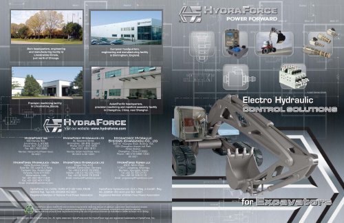
Main headquarters, engineering<br />
and manufacturing facility in<br />
Lincolnshire Illinois,<br />
just north of Chicago.<br />
European headquarters,<br />
engineering and manufacturing facility<br />
in Birmingham, England.<br />
Precision machining facility<br />
in Lincolnshire, Illinois.<br />
Asian/Pacific headquarters,<br />
precision machining and manifold assembly facility<br />
in Changzhou, China, near Shanghai.<br />
Electro Hydraulic<br />
CONTROL SOLUTIONS<br />
Visit our website: www.hydra<strong>for</strong>ce.com<br />
HYDRAFORCE INC<br />
500 Barclay Blvd.<br />
Lincolnshire, IL 60069<br />
Phone: 847 793 2300<br />
Fax: 847 793 0086<br />
Member: National Fluid Power Assoc.<br />
ISO 9001<br />
HYDRAFORCE HYDRAULICS – INDIA<br />
Vatika Business Centre<br />
Suite No. 22, Level 5, C Wing<br />
Techpark One, Airport Road<br />
Yerwada, Pune 411006<br />
Maharashtra, India<br />
Tel: +91 020 40111304<br />
Fax: +91 020 40111105<br />
Email: bharatb@hydra<strong>for</strong>ce.com<br />
HYDRAFORCE HYDRAULICS LTD<br />
St. Stephens Street<br />
Birmingham B6 4RG England<br />
Phone: 0121 333 1800<br />
Fax: 0121 333 1810<br />
Member: British Fluid Power Assoc.<br />
ISO 9001 & ISO 14001<br />
HYDRAFORCE HYDRAULICS LTD<br />
Prager Ring 4-12<br />
D-66482 Zweibrücken, Germany<br />
Tel: +49 (0) 6332 79 2350<br />
Mobile: +49 (0) 162 200 1553<br />
Fax: +49 (0) 6332 79 2359<br />
Email: markusb@hydra<strong>for</strong>ce.com<br />
HYDRAFORCE HYDRAULIC<br />
SYSTEMS (CHANGZHOU) CO., LTD<br />
388 W. Huanghe Road, Building 15A<br />
GDH Changzhou Airport Indl Park<br />
Xinbei District<br />
Changzhou, China 213022<br />
Phone: +86 519 6988 1200<br />
ISO 9001<br />
HYDRAFORCE KOREA LLC<br />
#306, Mirim Plaza<br />
1132-1, Jungdong, Wonmigu,<br />
Bucheon, Kyunggido, Korea<br />
Tel: +82 32 328 2170<br />
Fax: +82 32 328 2172<br />
Email: jong-seongl@hydra<strong>for</strong>ce.com<br />
<strong>HydraForce</strong>, Inc. (USA): DUNS #13-120-1493; FSCM<br />
#005K6 Fed. Tax #36-3555856 ISO 9001<br />
Registered Member of National Fluid Power Association<br />
<strong>HydraForce</strong> Hydraulics Ltd. (U.K.): Reg. in Cardiff.; Reg.<br />
No. 2286591 ISO 9001 and ISO 14001<br />
Registered Member of British Fluid Power Association<br />
<strong>HydraForce</strong> valves meet RoHS environmental requirements restricting the use of cadmium, quick silver, lead hexavalent chrome,<br />
polybrominated biphenyl (PPB) or polybrominated diphenyl ester (PPDE) in products, components and packing materials.<br />
All <strong>HydraForce</strong> products meet requirements limiting the use of hazardous materials as indentified in OSHA Standard 1910.1200(g).<br />
<strong>for</strong> <strong>Excavators</strong><br />
© Copyright 2012 <strong>HydraForce</strong>, Inc. All rights reserved. <strong>HydraForce</strong> and the <strong>HydraForce</strong> logo are registered trademarks of <strong>HydraForce</strong>, Inc.
TABLE OF CONTENTS<br />
Arm and Boom Suspension -<br />
Bucket, Arm, and Boom control.............Pages 6-7<br />
• Fixed or adaptable<br />
• Improved safety<br />
• Efficiency<br />
Mini and mid-range excavators up to 20 tons can gain the<br />
greatest benefit from inventive application of electrohydraulic<br />
controls. Virtually all movements of the cab, boom, arm, and<br />
bucket are hydraulically controlled and easy to integrate into<br />
hydraulic manifolds. <strong>HydraForce</strong>, with its comprehensive line<br />
of cartridge valves and manifold capabilities, can provide<br />
numerous custom control solutions <strong>for</strong> excavators.<br />
Ancillary Functions -<br />
Breaker, Grapple, Hammer, Auger,<br />
Quick Coupler............Pages 10-11<br />
Powertrain - Transmission, Drive Motors,<br />
Fan Drive, Clutch..........................Pages 4-5<br />
• Increased functionality<br />
• Wide range of adaptable<br />
solutions <strong>for</strong> precise control<br />
• Stand-alone or custom manifold<br />
designs<br />
• Flow capabilities up to<br />
380 lpm/100 gpm<br />
Main Controls -<br />
Boom, Bucket, Swing/Slew Motor,<br />
Return Manifold, Steering.............Pages 8-9<br />
• Low leakage load-holding<br />
• Meter-in/meter-out functionality<br />
• Electrohydraulic or hydraulic pilot<br />
• Bridge circuit technology<br />
• Reliability and safety<br />
• Precise control<br />
• Rugged and reliable<br />
• 10,000,000 cycle life testing<br />
• 1,000 hours salt spray rating<br />
• IP69K waterproof coil<br />
• Main system pressure regulation<br />
Electronic Controls.........Page 13<br />
• Rugged & reliable<br />
• Hardware & software<br />
• CoDeSys programming<br />
• Flexible configurations<br />
The <strong>HydraForce</strong><br />
Difference...........Page 12<br />
• Highest quality guaranteed<br />
• Speed to market<br />
• Flexible and responsive<br />
• Over 600 combined years of<br />
cartridge development<br />
experience<br />
• Industry standard cavities<br />
• Leading edge technology<br />
2 3
POWERTRAIN<br />
Transmission<br />
Drive Motors<br />
Fan Drives<br />
Clutch<br />
Excavator powertrain solutions encompass improvements<br />
on the transmission, drive motors, fan drives and clutch.<br />
Reducing emissions, noise, and vibration and improving<br />
speed, power and cooling are the goals. Operator com<strong>for</strong>t<br />
and productivity can be enhanced with improved fan and<br />
transmission control. Here are some ideas.<br />
Powertrain open loop cavitation protection<br />
Drive Motor<br />
Excavator Transmission Solution<br />
Four TS98-T34 valves are used to shift clutch packs.<br />
The TS98-T34 valve is a cost-effective, pilot-operated,<br />
spool-type proportional pressure reducing/relieving<br />
valve with a built-in solenoid coil.<br />
1st Gear 2nd Gear 3rd Gear Reverse<br />
1ST 2ND 3RD REV<br />
A logical and energy-saving solution <strong>for</strong><br />
anti-cavitation on the drive<br />
Excavator powertrain open loop systems are<br />
vulnerable to cavitation and, due to the great demand<br />
<strong>for</strong> hydraulic power and smooth operation, an anticavitation<br />
check valve is commonly employed to<br />
ease anti-cavitation. This, however, has drawbacks,<br />
these being energy consumption in heat generation,<br />
pressure rise of counterload at higher drive speeds<br />
and higher fuel consumption.<br />
Clutch Engagement Per<strong>for</strong>mance (TS98-T34)<br />
FWD<br />
EV20-S34<br />
CV42-M20<br />
TS38-20<br />
REV<br />
EV20-S34<br />
CV42-M20<br />
TS98-T34 TS98-T34 TS98-T34 TS98-T34<br />
RVD50-20<br />
<strong>HydraForce</strong> has another anti-cavitation solution –<br />
modulating the counter load with a simple circuit<br />
consisting of a proportional pressure control valve with<br />
two logic elements. This circuit adjusts the counter<br />
load to provide a constant load regardless of drive<br />
speed, reducing it to a very low load when not required.<br />
The result – less input energy and fuel consumption,<br />
CO2 output and oil cooling demand.<br />
Operator Input<br />
A<br />
DR<br />
Directional Valve<br />
B<br />
P<br />
Pump<br />
T<br />
Quiet down that fan drive. . .<br />
Fan drives controlled by hydraulic cartridge valves are<br />
quieter and run on less horsepower than mechanical<br />
fan drives, providing greater fuel economy <strong>for</strong> tractors.<br />
Reverse<br />
Pump<br />
P<br />
Fan Drive Solutions<br />
• Flow rates up to 190 lpm (50 gpm)<br />
• Fail safe high or low<br />
• Preconfigured controls available<br />
• Reduce horsepower consumption by up<br />
to 30%<br />
FWD<br />
Control valves with multiple temperature inputs can be<br />
used to provide variable fan speed control depending<br />
on air temperature, load, and cooling requirements.<br />
If the radiator gets clogged, two-position, four-way<br />
solenoid valves can automatically reverse fan direction.<br />
Electronic control of the hydraulic cooling system can<br />
be achieved using either an EFDR1 programmable<br />
valve driver or a CoreTek controller (ECU).<br />
Fan Output Per<strong>for</strong>mance<br />
TO<br />
ECM<br />
CoreTek<br />
Model<br />
ECU-0710<br />
CAN HI<br />
CAN LOW<br />
Plug-In<br />
Mount<br />
on<br />
Forward<br />
Valve<br />
4<br />
3<br />
2<br />
1<br />
TS98-T34<br />
Valves <strong>for</strong><br />
Clutch<br />
Control<br />
Forward<br />
Pump<br />
TS10-27<br />
4<br />
3<br />
SV10-40A<br />
REV<br />
TS10-27 Valve<br />
<strong>for</strong> Fan Control<br />
2<br />
1<br />
CV10-20<br />
T<br />
4 5
ARM AND BOOM SUSPENSION<br />
Bucket Control<br />
Arm Control<br />
Boom Control<br />
Faster, smoother, and more powerful arm<br />
and boom action is made possible with<br />
hydraulic cartridge valves. Regenerative<br />
circuits can save energy and improve<br />
cycle time. Flow sharing can smooth the<br />
control of lifting and load handling. Multifunction<br />
hydraulic controls can provide<br />
flexibility and ease of operation <strong>for</strong> bucket<br />
and attachments. Systems can be tailored<br />
to the customer’s exact requirements <strong>for</strong><br />
hydraulic flow and pressure.<br />
Systems Within Reach <strong>for</strong> Any Excavator<br />
No matter what size the excavator, <strong>HydraForce</strong> can create<br />
a suitable control system <strong>for</strong> bucket, arm, boom, and<br />
suspension. Systems can be designed to suit the exact<br />
requirements of the customer, and address special<br />
needs such as pressure spikes, energy-savings, and<br />
cost-savings.<br />
Pressure Spike Solution<br />
Here’s a clever way to solve the issue of pressure spikes.<br />
An EP valve can be used to reduce the overshoot spike<br />
in a closed center load-sensing system by popping open<br />
momentarily, allowing the hydraulic pump time to de-stroke<br />
when needed. As long as the spring value of the valve is<br />
slightly higher than the low-pressure standby setting of the<br />
pump, the valve will stay closed until the cylinder bottoms<br />
out. Since load-sense pressure is not maintained, the valve<br />
will open while the pump de-strokes, which effectively<br />
“clips” pressure spikes.<br />
To Main Valve<br />
P<br />
LS<br />
System Load Sense<br />
Load Sensing Pump<br />
EP10-S35<br />
Proportional Relief<br />
For high capacity systems, a proportional relief valve system<br />
can be a great relief <strong>for</strong> the excavator operator experiencing<br />
an overload. In this system, an electrohydraulic proportional<br />
TS valve is used to provide load-sensing relief of the EV<br />
directional element.<br />
To Main Valve<br />
TS38-20<br />
T<br />
Basic Boom Suspension Circuit<br />
This basic suspension circuit <strong>for</strong> a wheeled excavator, working<br />
in parallel to the main directional control valve, can be<br />
incorporated to damp the effects of rugged terrain on your<br />
load. This on-off solution, when energized, uses a piloted<br />
directional element combined with a damping accumulator<br />
to smooth out the bounce on the bucket, effectively keeping<br />
more of your load in your bucket during transport. When deenergized<br />
a network of check valves and tuned orifices are<br />
used to regulate accumulator pressure.<br />
The Unique Requirements <strong>for</strong> an Excavator Boom<br />
Suspension<br />
Excavator boom suspension systems are quite different from<br />
the ones used in wheel and backhoe loaders. Excavator<br />
booms can be single-piece (mono boom), or two-piece. Forces<br />
on the boom suspension cylinders will vary tremendously.<br />
Safety requirements are also different. Hose rupture valves<br />
(counterbalance valves) are absolutely necessary <strong>for</strong> the<br />
boom cylinders of an excavator.<br />
<strong>Excavators</strong> transport loads but they also per<strong>for</strong>m work from a<br />
stationary position. When excavating, there should be no drift<br />
of the boom when the suspension is switched off. The operator<br />
must be able to use the excavator <strong>for</strong> accurate work when<br />
not transporting a load.<br />
<strong>Excavators</strong> there<strong>for</strong>e need a completely customized control<br />
solution, which often has to be flanged directly on the boom<br />
cylinder(s) and take up as little space as possible.<br />
<strong>HydraForce</strong> cartridge valves and manifolds, especially the<br />
vibration-resistant HyPer<strong>for</strong>mance valves, are perfect <strong>for</strong><br />
use on excavators because they can be designed to fit a machine's<br />
tight clearance requirements and attach to a specific<br />
mounting bracket.<br />
CYL1<br />
CYL2<br />
A<br />
B<br />
CV1 ORF3<br />
PD1<br />
CV2<br />
ORF2<br />
ORF1<br />
SV1<br />
RV1<br />
ACC1<br />
NV1<br />
Acc<br />
T<br />
T1<br />
Figure 2: Without Boom Suspension<br />
Figure 3: With Boom Suspension<br />
Main Control Valve<br />
Pump<br />
Figure 1: Optimally sized custom boom<br />
suspension manifold<br />
EV20-S34<br />
P<br />
Pump<br />
T<br />
6 7
MAIN CONTROLS<br />
Boom<br />
Bucket<br />
Swing/Slew Motor<br />
Steering<br />
Excavator main controls are filled with opportunity <strong>for</strong> elegant electrohydraulic<br />
control of the bucket, boom, cab, stabilizers, swing or slew motor, and steering.<br />
Control of a “Walking” Excavator<br />
Excavating on a mountainside or in a riverbed can be easily accomplished with the help of a “walking” excavator. Its<br />
wheels are mounted on foldable “legs” that are controlled hydraulically by the same manifold that provides steering<br />
control. When the excavator works in a riverbed, the manifold and cartridge valving can be totally submerged in water,<br />
thanks to their corrosion-resistant coating.<br />
Low Leakage Bucket Control<br />
As excavator power and sophistication increase, so<br />
do flow rates. <strong>HydraForce</strong> SPCL16-40 valves control<br />
up to 152 lpm (40 gpm) while holding loads with<br />
extremely low leakage. This directional control circuit<br />
has a multiple load sense configuration. The highest<br />
load sense signal supplied through the highest pressure<br />
pilot line is used to provide compensated flow to<br />
either end of the cylinder. The bottom load sense port<br />
signals the compensator, which allows each SPCL<br />
valve to provide a consistent amount of flow to each<br />
function, independent of load-induced pressure.<br />
SPCL16-40<br />
Bucket<br />
SPCL16-40<br />
Steering<br />
SV10-47C<br />
SV10-47C<br />
SV10-47C<br />
SP10-47C<br />
SV10-47C<br />
SV10-47C<br />
SV10-47C<br />
SP10-47C<br />
SP10-47C<br />
Pump<br />
Tank<br />
Load Sensing Pump<br />
A HyPer<strong>for</strong>mance Solution to Prevent Swing<br />
Motor Cavitation<br />
Compact excavators often work in tight spaces and many<br />
have zero turn radius capability, which requires very<br />
smooth operation of swing or slewing function. The swing<br />
motor is often an open loop circuit requiring anti-cavitation.<br />
Here’s an option <strong>for</strong> preventing anti-cavitation of the<br />
hydraulic motor <strong>for</strong> excavator swing/slew functions. This<br />
circuit also reduces the number of hydraulic fittings and<br />
leakage points.<br />
Directional Bridge<br />
A bridge circuit provides complete control of lift and lower functions <strong>for</strong> excavators with low flow requirements. This<br />
configuration uses SPCL directional control valves, which eliminate additional load sense and load holding check<br />
valves. Both SPCLs use load pressure as the piloting signal.<br />
Directional Bridge Circuit<br />
A B A<br />
B<br />
LS04-B30<br />
SPCL16-40<br />
SPCL16-40<br />
SPCL10-30<br />
SPCL10-30<br />
RV08-29<br />
RV08-29<br />
EC16-32<br />
CV04-20<br />
EC10-32<br />
CV04-20<br />
P<br />
P<br />
LS<br />
T<br />
LS<br />
T<br />
8 9
ANCILLARY FUNCTIONS<br />
Breaker<br />
Grapple<br />
Hammer<br />
Auger<br />
Quick Coupler<br />
<strong>Excavators</strong>, especially the mini- and<br />
midi-sized models, can do much more<br />
than earthmoving and excavation. With<br />
the right attachments, an excavator can<br />
also be used <strong>for</strong> demolition, drilling, and<br />
material-handling – all with the power of<br />
electro-hydraulic control.<br />
Hammer Valve <strong>for</strong> Breaker<br />
This circuit provides responsive and smooth control of the<br />
fixed gear pump system <strong>for</strong> the breaker on a hydraulic<br />
excavator, using a solenoid valve, compensator, needle<br />
valve and relief valve. It has a maximum inlet flow of 180<br />
lpm/47 gpm and a working pressure of 250 bar/3,625 psi.<br />
NV1<br />
CF<br />
ORF1<br />
EF<br />
Quick Coupler Manifold<br />
A simple circuit consisting of a single solenoid, check and<br />
relief valve in a manifold provides fully customizable quick<br />
coupler <strong>for</strong> an attachment on a mini-excavator.<br />
PC08-30<br />
EXT<br />
RET<br />
Pilot Control Manifold <strong>for</strong> a Mini-Excavator Grapple<br />
This simple circuit provides pilot control of hydraulic pressure<br />
<strong>for</strong> a 1 to 2.6 ton excavator. It uses two solenoid valves, a<br />
pressure relief valve and four check valves.<br />
Pump 1<br />
Pump 2<br />
Pump 3<br />
CV08-20<br />
CV08-20<br />
CV08-20<br />
PR50-38<br />
SV08-40<br />
Tank<br />
EC1<br />
SV1<br />
RV1<br />
ORF1<br />
CV08-20<br />
170 bar<br />
P<br />
T<br />
MAX INLET FLOW: 180 l/min / 47 gpm<br />
MAX WORKING PRESSURE: 240 bar / 3500 psi<br />
Weather-Resistant Control of Electro-Hydraulic<br />
Functions<br />
For excavator applications requiring water and thermalshock<br />
resistance, try our E-series solenoid coils which<br />
meet IP69K standards. A corrosion-resistant coating (G) is<br />
also available on our entire line of cartridge valves to help<br />
guard against corrosion.<br />
Pump<br />
Tank<br />
SV98-T39<br />
SV98-T39<br />
Reduced-Cost Pilot Control Manifold <strong>for</strong> a Midi-Excavator<br />
In order to reduce the main circuit pressure to a lower range <strong>for</strong> the auxiliary functions, there is often a large steel or ductile<br />
iron manifold which uses a pressure reducing valve to decrease the high inlet pressure. With the unique PRES50-30 valve,<br />
the secondary manifold <strong>for</strong> the lower pressure auxiliary functions can be aluminum, reducing both cost and weight. The main<br />
system pressure is plumbed directly into the steel adapter of the PRES50-30, which can withstand up to 5000 psi. In the<br />
adapter, pressure is reduced to between 450 and 800 psi <strong>for</strong> downstream functions. Specifying aluminum instead of steel <strong>for</strong><br />
the manifold block, excavator manufacturers can reduce weight as well as cost <strong>for</strong> their machine. This circuit <strong>for</strong> an 8-ton excavator<br />
receives high pressure via the inlet of the PRES50-30 and reduces the pressure <strong>for</strong> use by the pilot control functions.<br />
Pump<br />
350 Bar / 5000 psi<br />
Pressure Reduced to 800 psi (55 bar)<br />
PRES50-30<br />
RV08-20<br />
CV08-20<br />
Accumulator<br />
Tank<br />
T1<br />
SV08-30<br />
SV08-30<br />
10 11
VALVES AND ELECTRONIC CONTROLS<br />
SPCL16-40<br />
Proportional Directional Control,<br />
4-Port, Normally Closed with Check<br />
Isolated Load Sense<br />
SPCL16-30<br />
Proportional Directional Control,<br />
3-Port, Normally Closed with Check<br />
Isolated Load Sense<br />
Electronic Controls<br />
Model ECU-0710<br />
Up to 27 inputs, consisting of digital, pulse, current<br />
measuring feedback and analog. A total of seven<br />
output configurations can be set, including six PWM<br />
or digital high-side drivers and a single low-side<br />
driver.<br />
Flow: 152 lpm/40 gpm<br />
Pressure: 250 bar (3625 psi)<br />
HSV10-47C<br />
High Pressure Spool 4-Port,<br />
3-Position, Closed Center<br />
3<br />
Flow: 152 lpm/40 gpm<br />
Pressure: 250 bar (3625 psi)<br />
PRES50-30<br />
Pressure Reducing/Relieving Valve<br />
Model ECU-2415<br />
Up to 39 digital, pulse, current measuring feedback<br />
and analog inputs along with 24 outputs consisting of<br />
up to 24 PWM or digital high-side drivers.<br />
Model ECU-2032<br />
Up to 52 inputs and 20 outputs consisting of up to<br />
eight PWM or 20 digital high-side drivers.<br />
Model ECU-2820<br />
Up to 52 inputs and 28 outputs consisting of up to 24<br />
PWM or digital high-side drivers and up to four digital<br />
low-side drivers.<br />
3<br />
Flow: 37.9 lpm/10 gpm<br />
Pressure: 350 bar (5075 psi)<br />
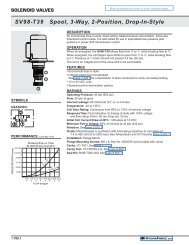
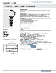
SV98-T39<br />
Spool-Type, 2-Position, 3-Way,<br />
Drop-in<br />
2<br />
1<br />
Flow: up to 11.4 lpm/3.0 gpm<br />
Pressure: 345 bar (5000 psi)<br />
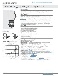
TSxx-27<br />
Proportional Pressure Control, Pilot-<br />
Operated Relief<br />
CORETEK PROGRAMMABLE<br />
MACHINE CONTROLLERS<br />
The new CoreTek line of general-purpose programmable<br />
controllers can be used as stand-alone<br />
controllers or integrated with other CAN networked<br />
devices. They are designed to withstand the environmental<br />
demands of mobile off-highway equipment<br />
applications. They feature flexible input and<br />
output configuration and are capable of driving up to<br />
3.0 amps per output pin.<br />
CoreTek controllers are fully sealed within a compact<br />
cast aluminum housing. Operating temperature<br />
range is -40° to +70°C (-40° to 158°F) and no external<br />
cooling or heat dissipation is required.<br />
SENSOR VALVES<br />
Select <strong>HydraForce</strong> valves can be<br />
ordered with an integral position<br />
sensing option capable of<br />
transmitting an on or off signal.<br />
This new sensing solution was<br />
designed <strong>for</strong> interchangeable use<br />
with existing <strong>HydraForce</strong> cartridge<br />
valves, is compatible with manual<br />
override options and uses an<br />
industry standard cavity.<br />
1<br />
2<br />
Flow: Up to 30 lpm/8 gpm<br />
Pressure: 45 bar (650 psi)<br />
Flow: up to 189 lpm/50 gpm<br />
Pressure: 241 bar (3500 psi)<br />
Our Breadth of Product<br />
As the largest manufacturer of hydraulic cartridge valves in the world, <strong>HydraForce</strong> offers an extensive range of solenoid,<br />
electro-proportional, directional, flow, and pressure control valves. In 2011, more than 200 new valves were introduced,<br />
including many high pressure and multi-function models. Cartridge valves <strong>for</strong> flow rates up to 379 lpm/100 gpm and<br />
operating pressures up to 350 bar/5,000 psi are sold individually, with housings or in manifold blocks. Valves can be<br />
custom-designed or standard product.<br />
<strong>HydraForce</strong> designs, manufactures and supports valve, manifold and accessory products supported by heavy duty<br />
electronic machine control capabilities.<br />
To request a free hydraulic integrated circuit (HIC) consultation, please visit:<br />
http://info.hydra<strong>for</strong>ce.com/Free-Custom-Circuit-Consultation/<br />
CoDeSys TM Programming<br />
CoDeSys or Controlled Development System is a<br />
complete development environment <strong>for</strong> Programmable<br />
Machine Controllers. The editors and debugging<br />
functions are based on the proven development<br />
program environments of advanced programming<br />
languages (such as Visual C++).<br />
CoDeSys software is available as a free download<br />
from <strong>HydraForce</strong>:<br />
http://www.hydra<strong>for</strong>ce.com/Electronics/<br />
CoDeSys software: Copyright © 3S - Smart Software Solutions GmbH<br />
HEAVY DUTY SENSORS<br />
<strong>HydraForce</strong> has accurate sensors designed <strong>for</strong> off-road applications.<br />
Our temperature sensors are thermistor style with padded resistors.<br />
ERT 120 – Output Signal: 5427.9 to 436.3 ohms<br />
Our pressure sensors have 1% total error band accuracy, are IP67 rated.<br />
ERP035 – <strong>for</strong> pressure ranges up to 35 bar (500 psi)<br />
ERP414 – <strong>for</strong> higher pressures up to 414 bar (6000 psi)<br />
12 13
OUR STORY<br />
Our Story<br />
The <strong>HydraForce</strong> story began in 1985 when the company<br />
was founded near Chicago by several partners who saw<br />
the mobile equipment industry’s need <strong>for</strong> quality hydraulic<br />
cartridge valves and manifolds delivered in a timely and<br />
responsive manner. They also saw the potential <strong>for</strong><br />
engineering innovation and design flexibility offered by<br />
cost-effective and space-saving cartridge valves and<br />
hydraulic integrated circuits.<br />
Since its founding, <strong>HydraForce</strong> continues to be a<br />
privately held company as it has grown to several<br />
manufacturing locations in North America, Europe and<br />
Asia, with a network of 120 stocking distributors who can<br />
offer local support across the globe.<br />
To maintain our core competency of speed to market,<br />
<strong>HydraForce</strong> has invested in application technical support<br />
tools including i-Design, our free hydraulic system design<br />
sofware, which integrates seamlessly with 3rd party<br />
simulation software, monthly webinars on new products<br />
and application tips, and an online product catalog.<br />
All <strong>HydraForce</strong> products carry a five-year limited<br />
warranty against defects in material and workmanship.<br />
<strong>HydraForce</strong> Vision<br />
To Be An Independent<br />
Provider Of Innovative<br />
Technical Solutions<br />
That Can Change The<br />
World<br />
Mission Statement<br />
To Provide Our Customers<br />
With The Highest Quality<br />
Hydraulic Valves And The<br />
Most Responsive Customer<br />
Support In The World<br />
Our Quality and Manufacturing Guarantee<br />
All three <strong>HydraForce</strong> plants in North America, Europe<br />
and Asia follow the same manufacturing processes and<br />
standards to ensure global consistency in product quality.<br />
• All products 100% tested<br />
• Use of Lean and Six Sigma practices<br />
• New product introduction tools such as:<br />
• Advanced Product Quality Planning (APQP)<br />
• Production Part Approval Process (PPAP)<br />
• Failure Mode and Effect Analysis (FMEA)<br />
• Statistical Process Control (SPC)<br />
• Continuous improvement through Kaizen<br />
• Responsive delivery with Kanban throughput system<br />
<strong>HydraForce</strong> Timeline<br />
1985<br />
<strong>HydraForce</strong> is created<br />
on principles of highest<br />
quality and customer<br />
response<br />
1988<br />
Achieved Ford Q1<br />
quality certification<br />
on first audit<br />
1991<br />
Achieved<br />
ISO 9001<br />
1993<br />
Achieved<br />
QS9000<br />
2006<br />
Received<br />
ISO 14001:2004<br />
2008<br />
Opened<br />
office in<br />
India<br />
2012<br />
To date, 13 patents<br />
have been awarded<br />
<strong>for</strong> innovative valve<br />
designs<br />
Received ISO 13849<br />
1985 1988 1990 1991 1995 2000 2005 2010 2011 2015 2020<br />
1989<br />
Opened<br />
European<br />
operation<br />
Worldwide Support<br />
1993<br />
Moved into<br />
Lincolnshire<br />
operation<br />
1997<br />
Expanded global<br />
headquarters<br />
by 50,000 sqft &<br />
opened Plant #2<br />
1999<br />
<strong>HydraForce</strong><br />
became #1 global<br />
manufacturer<br />
of cartridge valves<br />
2001<br />
Expanded global<br />
headquarters<br />
by 70,000 sqft &<br />
built new 50,000 sqft<br />
EU Operation<br />
2010<br />
Formalized 2015<br />
Strategic Plan &<br />
paid off all long<br />
term debt<br />
2011<br />
Opened 4th global<br />
mfg operation in<br />
China<br />
2005<br />
Opened offices<br />
in Korea, and<br />
China<br />
ISO 9001<br />
Continue<br />
global<br />
expansion<br />
MANUFACTURING<br />
TECHNICAL SALES<br />
DISTRIBUTION & SUPPORT<br />
14 15