Transport in PEMFC Stacks - DOE Hydrogen and Fuel Cells ...
Transport in PEMFC Stacks - DOE Hydrogen and Fuel Cells ...
Transport in PEMFC Stacks - DOE Hydrogen and Fuel Cells ...

You also want an ePaper? Increase the reach of your titles
YUMPU automatically turns print PDFs into web optimized ePapers that Google loves.
<strong>Transport</strong> <strong>in</strong> <strong>PEMFC</strong> <strong>Stacks</strong><br />
G<strong>in</strong>er, Inc.<br />
Hui Xu<br />
Junq<strong>in</strong>g Ma<br />
Cortney Mittelsteadt (PI)<br />
University of South Carol<strong>in</strong>a<br />
John Van Zee<br />
Sirivatch Shimpalee<br />
Visarn Lilavivat<br />
Jason Morgan<br />
Ballard Material Products<br />
Don Connors<br />
Guy Ebbrell<br />
Virg<strong>in</strong>ia Tech<br />
James McGrath<br />
Yu Chen<br />
Jarrett Rowle<br />
Andy Shaver<br />
Chang Hyun Lee<br />
Tech Etch<br />
Kev<strong>in</strong> Russell<br />
Project ID #<br />
FC054<br />
This presentation does not conta<strong>in</strong> any proprietary, confidential,<br />
or otherwise restricted <strong>in</strong>formation<br />
1
<strong>Transport</strong> <strong>in</strong> <strong>PEMFC</strong> <strong>Stacks</strong><br />
Timel<strong>in</strong>e<br />
• Project Start Date: 11/1/2009<br />
• Project End Date: 8/31/2013<br />
• Percent Complete: 60%<br />
Budget<br />
• Total Project Fund<strong>in</strong>g: $3.340M<br />
– <strong>DOE</strong> Share $2.662M<br />
– Cost Share $ 0.678M<br />
• Fund<strong>in</strong>g Received <strong>in</strong> FY11: $786K<br />
• Planned Fund<strong>in</strong>g for FY12: $300K<br />
Barriers Addressed<br />
• Performance<br />
• Water <strong>Transport</strong> with<strong>in</strong> Stack<br />
• System Thermal <strong>and</strong> Water Management<br />
• Start-Up <strong>and</strong> Shut Down<br />
Technical Targets<br />
• Cold Start-up Times<br />
• Specific Power Density<br />
• Stack Power Density<br />
• Stack Efficiency<br />
Partners<br />
• University of South Carol<strong>in</strong>a<br />
• Virg<strong>in</strong>ia Tech<br />
• Tech Etch<br />
• Eng<strong>in</strong>eered Fiber Technologies<br />
This presentation does not conta<strong>in</strong> any proprietary, confidential,<br />
or otherwise restricted <strong>in</strong>formation<br />
2
Approach: Team <strong>and</strong> Tasks<br />
Objective: Improve Underst<strong>and</strong><strong>in</strong>g/Correlation Between<br />
Material Properties <strong>and</strong> Model Equations<br />
Diffusion<br />
Media<br />
Fabrication<br />
<strong>and</strong> Properties<br />
EFT<br />
Synthesis <strong>and</strong><br />
nano-scale PEM<br />
characterization<br />
Virg<strong>in</strong>ia Tech<br />
<strong>Fuel</strong> Cell<br />
Test<strong>in</strong>g <strong>and</strong><br />
Model<strong>in</strong>g<br />
University of<br />
South Carol<strong>in</strong>a<br />
MEA<br />
Fabrication<br />
<strong>and</strong> Properties<br />
G<strong>in</strong>er<br />
GES<br />
Bipolar Plate<br />
Fabrication<br />
<strong>and</strong> Properties<br />
Tech-Etch<br />
• Generate model<br />
• Supply model relevant transport numbers<br />
• Stress the model by develop<strong>in</strong>g different<br />
materials with different transport<br />
properties<br />
• Determ<strong>in</strong>e sensitivity of fuel cell<br />
performance to different factors<br />
• Guide research<br />
Milestone Plan Complete Actual Complete<br />
Basel<strong>in</strong>e PFSA model, with overall results correlat<strong>in</strong>g with<strong>in</strong> +-20% of each other.<br />
Design the new apparatus for extend<strong>in</strong>g the range of electroosmotic drag <strong>and</strong> diffusivity.<br />
Extend Model to a variety of membranes, catalyst content, GDM’s, <strong>and</strong> flow fields. The<br />
model should be able to demonstrate prediction of the actual data with<strong>in</strong> +-20% of the<br />
experimental results.<br />
4/15/2011 4/1/2011<br />
8/15/2012 60%<br />
This presentation does not conta<strong>in</strong> any proprietary, confidential,<br />
or otherwise restricted <strong>in</strong>formation<br />
3
Approach & Milestones<br />
Year Techniques Materials Model<strong>in</strong>g<br />
Year 1<br />
Year 2<br />
Year 3<br />
(Period 2)<br />
New technique generation for static <strong>and</strong><br />
dynamic diffusion, EODC, through plane<br />
conductivity confirmation with Basel<strong>in</strong>e<br />
materials. (90%)<br />
Current Distribution Board Demonstration<br />
(100%)<br />
Techniques applied to alternative<br />
materials.<br />
Diffusivity apparatus used to characterize<br />
alternative diffusion media.<br />
Low Temperature Studies<br />
Basel<strong>in</strong>e hydrocarbon PEM<br />
generated <strong>and</strong> down selected<br />
(80%)<br />
Basel<strong>in</strong>e Gas diffusion Media<br />
Delivered (100%)<br />
First Etched Plates (100%)<br />
Scale-up of Basel<strong>in</strong>e PEM<br />
Integration of catalysts<br />
Modification of diffusion media<br />
Alternative Plates & Design of<br />
larger plates.<br />
Delivery of Large PEMs<br />
Current Distribution board for<br />
larger plate<br />
Fabrication of larger plate <strong>and</strong><br />
current distribution board<br />
Set-Up of Model<br />
Use of Basel<strong>in</strong>e materials for<br />
Test<strong>in</strong>g Model Sensitivity<br />
Test<strong>in</strong>g<br />
Performance <strong>and</strong> water<br />
balance modeled <strong>and</strong><br />
confirmed with basel<strong>in</strong>e<br />
materials <strong>and</strong> hydrocarbon<br />
PEM. (50%)<br />
Alternative diffusion media<br />
tested.<br />
Model<strong>in</strong>g extended to larger<br />
cells.<br />
Effect of coolant/heat transfer.<br />
Model confirmation with<br />
current distribution <strong>and</strong> water<br />
balance.<br />
This presentation does not conta<strong>in</strong> any proprietary, confidential,<br />
or otherwise restricted <strong>in</strong>formation<br />
4
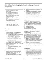
Relevance: Use of Model<strong>in</strong>g <strong>in</strong> <strong>Fuel</strong> Cell Development is Widespread.<br />
Agreement on Fundamentals is Not.<br />
• In develop<strong>in</strong>g a model for transport <strong>in</strong><br />
fuel cell systems, the first th<strong>in</strong>g that is<br />
needed is the key transport numbers<br />
– Diffusivity<br />
– Water Uptake<br />
– Electro-osmotic Drag<br />
– Through Plane Conductivity<br />
• NOTHING EVEN RESEMBLING<br />
CONSENSUS ON THESE<br />
FUNDAMENTALS<br />
• Systematic approach of generat<strong>in</strong>g <strong>and</strong><br />
develop<strong>in</strong>g various materials with<br />
better characterization methods is<br />
needed<br />
Diffusion Coefficient (cm 2 s -1 X 10 6 )<br />
30.00<br />
25.00<br />
20.00<br />
15.00<br />
10.00<br />
5.00<br />
Zawodz<strong>in</strong>ski, et. al.<br />
Our Data<br />
0.00<br />
0.00 2.00 4.00 6.00 8.00 10.00 12.00 14.00<br />
Average Water Content (λ)<br />
Fuller, et. al.<br />
White, et. al.<br />
T.A. Zawodz<strong>in</strong>ski, M. Neeman, L.O. Sillerud <strong>and</strong> S. Gottesfeld, J. Phys.<br />
Chem., 95, 6040 (1990)<br />
T.F. Fuller, Ph.D. Thesis, University of California, Berkeley, CA (1992)<br />
T.V. Nguyen <strong>and</strong> R.E. White, J. Electrochem. Soc., 140, 2178 (1993)<br />
Equations of the form of: S. Motupally, A.J. Becker <strong>and</strong> J.W. Weidner, J.<br />
Electrochem. Soc., 147, 3171 (2000)<br />
This presentation does not conta<strong>in</strong> any proprietary, confidential,<br />
or otherwise restricted <strong>in</strong>formation<br />
5
Achievements: New Membranes: HQS100-6FPAEB<br />
BPSH100*<br />
O<br />
O<br />
H O 3 S<br />
O<br />
S<br />
O<br />
Chemical Formula: C 24 H 16 O 10 S 3<br />
••<br />
Molecular Weight: 560.57<br />
IEC = 3.57 meq/g<br />
SO 3 H<br />
*BiPhenol Sulfone, 100% sulfonated H + form<br />
n<br />
HQSH100*<br />
O<br />
IEC = 4.13 meq/g<br />
O<br />
H O 3 S<br />
O<br />
S<br />
O<br />
SO 3 H<br />
Chemical Formula: C 18 H 12 O 10 S 3<br />
••<br />
Molecular Weight: 484.48<br />
*Hydroqu<strong>in</strong>one Sulfone, 100% sulfonated H + form<br />
n<br />
SQSH*<br />
O<br />
SO 3<br />
H<br />
O<br />
H O 3 S<br />
O<br />
S<br />
O<br />
SO 3<br />
H<br />
Chemical Formula: C 18 H 12 O 13 S 4<br />
••<br />
Molecular Weight: 564.54<br />
IEC = 5.31 meq/g<br />
*Sulfonated Qu<strong>in</strong>one-Sulfone, H + form<br />
n<br />
• Provide design guidel<strong>in</strong>es for PEMs on impact of structure <strong>and</strong> segregation of charges<br />
• G<strong>in</strong>er to use polymer powders to determ<strong>in</strong>e fundamental properties, generate MEAs<br />
• USC to use model to predict performance based on fundamental properties<br />
Proton conductivity@80 o C [Scm -1 ]<br />
10 0<br />
10 -1<br />
(4)<br />
(3)<br />
10 -2<br />
10 -3<br />
10 -4<br />
(2)<br />
(1)<br />
(1) Nafion 212<br />
(2) 6FPAEB-BPSH 9k-9k<br />
(3) 6FPAEB-HQSH 6k-6k<br />
(4) 6FPAEB-HQSH 9k-9k<br />
20 30 40 50 60 70 80 90 100<br />
Relative humidity [%]<br />
This presentation does not conta<strong>in</strong> any proprietary, confidential,<br />
or otherwise restricted <strong>in</strong>formation<br />
6
Achievements: New Membranes: MEA Fabrication<br />
Solution<br />
Cast<br />
Decal<br />
Transfer<br />
4'' x 4''<br />
50cm 2 FCT plates<br />
VA Tech: Polymer<br />
Synthesis<br />
12'' x 5''<br />
G<strong>in</strong>er: Membrane cast & characterization:<br />
water uptake, diffusivity, electro-osmotic drag<br />
coefficient (EODC), MEA fabrication<br />
50cm 2 GM plates<br />
South Carol<strong>in</strong>a:<br />
Performance evaluation<br />
<strong>and</strong> model validation<br />
This presentation does not conta<strong>in</strong> any proprietary, confidential,<br />
or otherwise restricted <strong>in</strong>formation<br />
7<br />
7
Achievements: New Technique: Simultaneous Water Uptake <strong>and</strong> Diffusivity<br />
oven<br />
pressure transducer<br />
membrane<br />
N212 at 80°C<br />
water reservoir<br />
pulse valve<br />
membrane<br />
chamber<br />
manual valve<br />
3-way valve<br />
water trap<br />
vacuum pump<br />
Non-membrane diffusion is elim<strong>in</strong>ated by avoid<strong>in</strong>g <strong>in</strong>erts <strong>in</strong> the system<br />
• Automation of dynamic system assures cont<strong>in</strong>uous diffusivity measurements at a variety of relative<br />
humidity;<br />
• Process simple, effective, <strong>and</strong> accurate, open to other researchers <strong>in</strong> fuel cell community<br />
This presentation does not conta<strong>in</strong> any proprietary, confidential,<br />
or otherwise restricted <strong>in</strong>formation<br />
8
Achievements: New Technique: Simultaneous Water Uptake <strong>and</strong> Diffusivity<br />
Operation T: 80°C<br />
Diffusivity (cm 2 /s, 10 -6 )<br />
4.0<br />
3.5<br />
3.0<br />
2.5<br />
2.0<br />
1.5<br />
1.0<br />
Nafion 112 (static result)<br />
Nafion 112 (Dynamic test)<br />
BPSH-6FBA 7k-7k Cast at G<strong>in</strong>er 3mil (Static results)<br />
BPSH-6FBA 7k-7k Cast at G<strong>in</strong>er 1.5-2mil (Static results)<br />
BPSH-6FBA 7k-7k Cast at G<strong>in</strong>er 3mil (dynamic results)<br />
BPSH-6FBA Na form 7k-7k Cast at G<strong>in</strong>er 3mil (dynamic results)<br />
0.5<br />
Nafion is a registered trademark of E.I. du Pont de Nemours <strong>and</strong> Company<br />
0.0<br />
0 2 4 6 8 10<br />
Lamda (mol H 2 O/mol SO 3 )<br />
Similar Isotherms seen for both PFSA <strong>and</strong> hydrocarbon-based ionomers<br />
Diffusivity of PFSA > Block Hydrocarbons <strong>in</strong> H + form >> Na + form<br />
This presentation does not conta<strong>in</strong> any proprietary, confidential,<br />
or otherwise restricted <strong>in</strong>formation<br />
9
Achievements: New Technique: EODC<br />
Water Reservoir<br />
Micro-flow Meter<br />
H 2<br />
Pressure Controller<br />
Saturator Oven<br />
H 2 O<br />
Membrane<br />
Saturator<br />
H 2 +H 2 O<br />
Insulated<br />
Heat Pipe<br />
Pressure<br />
Transducer<br />
H 2 Pump Oven<br />
RH Meter<br />
???<br />
#H 2 O/H +<br />
H 2 - 2e - → 2H + 2H + + 2e - → H 2<br />
H 2 Pump Cell<br />
Pressure<br />
Transducer<br />
RH Meter<br />
Proportional<br />
Valve<br />
• Water/H 2 <strong>in</strong>let ratio<br />
controlled by<br />
controll<strong>in</strong>g saturator<br />
temperature <strong>and</strong> H 2<br />
pressure<br />
• If ratio is too high, not<br />
enough water is<br />
dragged across <strong>and</strong> cell<br />
floods <strong>and</strong> fails<br />
• If ratio is too low,<br />
membrane dries out<br />
<strong>and</strong> cell fails<br />
• At Water/H 2 =<br />
2*EODC Cell operates<br />
<strong>in</strong> quasi-stable state<br />
Vacuum Pump<br />
Water Trap<br />
All gas/gas diffusion is elim<strong>in</strong>ated<br />
This presentation does not conta<strong>in</strong> any proprietary, confidential,<br />
or otherwise restricted <strong>in</strong>formation<br />
10
Cell Voltage (V)<br />
Maxiumum Stabilibity Time (m<strong>in</strong>)<br />
0.8<br />
0.7<br />
0.6<br />
0.5<br />
0.4<br />
0.3<br />
0.2<br />
0.1<br />
0<br />
Feed ratio 0.21 Feed ratio 0.42<br />
Feed ratio 0.58 Feed ratio 0.71<br />
Feed ratio 0.76 Feed ratio 0.85<br />
0 20 40 60 80 100 120 140<br />
Time (m<strong>in</strong>ute)<br />
140<br />
120<br />
100<br />
80<br />
60<br />
40<br />
20<br />
0<br />
Nafion 115 Expt. 1<br />
Nafion 115 Expt. 2<br />
Nafion 115 Expt. 3<br />
Dry<strong>in</strong>g<br />
out<br />
Achievements: New Technique: EODC<br />
Nafion ® 115, 80 °C <strong>and</strong> 82% RH, 100 mA/cm 2<br />
0 0.2 0.4 0.6 0.8 1<br />
Feed Ratio (F)<br />
Flood<strong>in</strong>g<br />
EODC nH2O/H +<br />
EODC nH2O/H +<br />
2.0<br />
2.0<br />
1.5<br />
1.5<br />
1.0<br />
1.0<br />
0.5<br />
0.5<br />
0.0<br />
0.0<br />
This presentation does not conta<strong>in</strong> any proprietary, confidential,<br />
or otherwise restricted <strong>in</strong>formation<br />
Nafion<br />
Nafion 112,<br />
112,<br />
112, 80°C<br />
80°C<br />
80°C<br />
Nafion Nafion 117, 117, 80°C 80°C<br />
1:<br />
Nafion 1: Fuller Fuller et<br />
117, et al (Nafion<br />
80°C al (Nafion 117, 117, 25°C) 25°C)<br />
2: Zawodz<strong>in</strong>ski et al (Nafion 117, 30°C)<br />
Nafion 2: Zawodz<strong>in</strong>ski 112, 80°C et al (Nafion Nafion 117, 117, 30°C)<br />
3: Aotani et al (Nafion 115, 70°C)<br />
80°C<br />
VT 3: 6FPAEB-BPSH100 Aotani et al (Nafion 7k-7k, 115, 70°C) 1.55IEC<br />
4: Ge et al (Nafion 117, 30°C)<br />
VT VT 6FPAEB-BPSH100 7k-7k, 7k-7k, 1.55IEC 1.55IEC<br />
VT<br />
VT<br />
VT 6FPAEB-BPSH100<br />
6FPAEB-BPSH100 14k-14k,<br />
14k-14k, 1.55IEC<br />
1.55IEC<br />
0 0 2 2 4 4 6 6 8 8 10 10 12<br />
12<br />
Lamda nH nH 2 O/SOH 2 3<br />
3<br />
• EODC of hydrocarbon-based materials slightly lower, but similar trend<br />
• Still work<strong>in</strong>g on consensus<br />
11
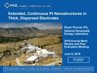
Achievements: New Materials: Diffusion Media<br />
• Ballard added to the<br />
program recently<br />
• Started with Toray<br />
Materials<br />
– Variable Wet-Proof<strong>in</strong>g<br />
– Microporous Layer<br />
• Ballard will provide more<br />
custom materials<br />
• Want to generate<br />
differences <strong>in</strong>:<br />
– MacMull<strong>in</strong> Number<br />
• Porosity<br />
• Tortuosity<br />
– Hydrophobicity<br />
•Tortuosity<br />
– Ratio of the actual path<br />
length through the pores to<br />
the shortest l<strong>in</strong>ear distance<br />
between two po<strong>in</strong>ts.<br />
•Porosity<br />
– Ratio of void volume (volume<br />
of pores) to the total volume.<br />
•MacMull<strong>in</strong> Number<br />
– Function of tortuosity <strong>and</strong><br />
pososity.<br />
N<br />
M<br />
L<br />
t<br />
V Pores<br />
V Total<br />
n<br />
τ<br />
= f ( τε , ) =<br />
m<br />
ε<br />
τ =<br />
L<br />
t<br />
V<br />
ε =<br />
V<br />
Pores<br />
Total<br />
This presentation does not conta<strong>in</strong> any proprietary, confidential,<br />
or otherwise restricted <strong>in</strong>formation<br />
12
Achievements: Design of Gas Diffusion Media<br />
Substrate<br />
P50<br />
EP40<br />
P75<br />
Diffusivity<br />
Modification<br />
Low<br />
High<br />
MPL 1<br />
MPL 2<br />
Carbon Substrate<br />
MPL 1/MPL2<br />
(carbon particle size)<br />
Small/Large<br />
Large/Small<br />
Basel<strong>in</strong>e Material at start<br />
of program was Toray<br />
H060<br />
The new design of GDLs have<br />
been modified from st<strong>and</strong>ard<br />
Ballard GDLs by add<strong>in</strong>g two<br />
micro porous layers. Each set<br />
has been treated with two<br />
different methods <strong>in</strong> order to<br />
provide two different values of<br />
diffusivity.<br />
Total of 12 new papers generated<br />
5 characterized ex-situ to date<br />
This presentation does not conta<strong>in</strong> any proprietary, confidential,<br />
or otherwise restricted <strong>in</strong>formation<br />
13
Achievements: Design of Gas Diffusion Media<br />
Comparison of Mercury pore size distributions of new design GDLs<br />
Cumulative Intrusion Volume (mL/g)<br />
Incremental Intrusion Volume (mL/g)<br />
4.5<br />
4<br />
3.5<br />
3<br />
2.5<br />
2<br />
1.5<br />
1<br />
0.5<br />
0<br />
0.001 0.01 0.1 1 10 100 1000<br />
Pore Size Diameter (µm)<br />
1.4<br />
1.2<br />
1<br />
0.8<br />
0.6<br />
0.4<br />
0.2<br />
Basel<strong>in</strong>e Substrates<br />
EP40T<br />
P50T<br />
P75T<br />
EP40T<br />
P50T<br />
P75T<br />
0<br />
0.001 0.01 0.1 1 10 100 1000<br />
Pore Size Diameter (µm)<br />
Cumulative Intrusion Volume (mL/g)<br />
Incremental Intrusion Volume (mL/g)<br />
2.5<br />
2<br />
1.5<br />
Cumulative pore volume<br />
1<br />
0.5<br />
0<br />
0.001 0.01 0.1 1 10 100 1000<br />
Pore Size Diameter (µm)<br />
0.7<br />
0.6<br />
0.5<br />
0.4<br />
0.3<br />
0.2<br />
0.1<br />
P50T_basel<strong>in</strong>e<br />
P50_Low<br />
P50_High<br />
Differential pore volume<br />
Modified Substrates<br />
P50T_basel<strong>in</strong>e<br />
P50_Low<br />
P50_High<br />
0<br />
0.001 0.01 0.1 1 10 100 1000<br />
Pore Size Diameter (µm)<br />
This presentation does not conta<strong>in</strong> any proprietary, confidential,<br />
or otherwise restricted <strong>in</strong>formation<br />
EP40T has largest<br />
pore volume,<br />
concentrated at 50<br />
µm<br />
Modification greatly<br />
reduces volume of<br />
large pores<br />
14
Voltage (V)<br />
Voltage (V)<br />
1<br />
0.9<br />
0.8<br />
0.7<br />
0.6<br />
0.5<br />
0.4<br />
0.3<br />
0.2<br />
0 500 1000 1500 2000<br />
1<br />
0.9<br />
0.8<br />
0.7<br />
0.6<br />
0.5<br />
0.4<br />
0.3<br />
Achievements: Design of Gas Diffusion Media<br />
Gore 57 Series 80°C<br />
P50T<br />
EP40T<br />
P75T<br />
Current density (mA/cm 2 )<br />
A: P75T, C: EP40T<br />
25%/25% RH anode/cathode:80 o C, 1.5/2.0 Stoich<br />
P50T<br />
EP40T<br />
P75T<br />
A: P75T, C: EP40T<br />
75%/25% RH anode/cathode:80 o C, 1.5/2.0 Stoich<br />
0.2<br />
0 500 1000 1500 2000<br />
Current density (mA/cm 2 )<br />
Voltage (V)<br />
This presentation does not conta<strong>in</strong> any proprietary, confidential,<br />
or otherwise restricted <strong>in</strong>formation<br />
1<br />
0.9<br />
0.8<br />
0.7<br />
0.6<br />
0.5<br />
0.4<br />
0.3<br />
0.2<br />
P50T<br />
EP40T<br />
P75T<br />
A: P75T, C: EP40T<br />
100%/50% RH anode/cathode:80 o C,1.5/2.0Stoich<br />
5psi<br />
0 500 1000 1500 2000<br />
Current density (mA/cm 2 )<br />
• P75T GDL shows the highest performance at lower<br />
humidity condition whereas EP40T shows the<br />
highest performance at higher humidity condition.<br />
• P75T will be used <strong>in</strong> the anode <strong>and</strong> EP40T will be<br />
used <strong>in</strong> the cathode <strong>in</strong> follow<strong>in</strong>g basel<strong>in</strong>e test<strong>in</strong>g<br />
15
Achievements: Design of Gas Diffusion Media: Wet Proof<strong>in</strong>g<br />
MacMull<strong>in</strong> Number (Dimensionless)<br />
6<br />
5<br />
4<br />
3<br />
2<br />
1<br />
0<br />
Papers with MPL<br />
Ballard Papers<br />
Toray Papers<br />
Modified Ballard Papers<br />
0 10 40 10-<br />
10<br />
10-<br />
40<br />
40-<br />
10<br />
% Wet Proof<strong>in</strong>g Substrate-<br />
MPL<br />
MacMull<strong>in</strong> number as function<br />
of porosity<br />
Difficult to make general<br />
relationship of N M (ε)<br />
40-<br />
40<br />
MacMull<strong>in</strong> Number (Dimensionless)<br />
5<br />
4<br />
3<br />
2<br />
1<br />
0<br />
MacMull<strong>in</strong> number as function of wet<br />
proof<strong>in</strong>g <strong>in</strong> substrate <strong>and</strong> MPL<br />
Mitsubishi Rayon<br />
ε -3.8<br />
Toray 40%<br />
Toray 10% PTFE<br />
Bruggeman<br />
Ballard AdvCarb<br />
ε -1.5<br />
-1.5 Showa Denka SCT-<br />
NF2-1<br />
P50 Low<br />
P75 Low<br />
Toray 40-40 P50 High<br />
P75 High<br />
W.L. Gore Carbel,<br />
Carbon Cloth<br />
Carbon Papers Cloth<br />
Paper Carbon Carbon<br />
+MPL Papers Cloth<br />
Ballard Paper Carbon +MPL Basel<strong>in</strong>e Cloth Papers Paper<br />
Ballard Carbon Paper Modified Basel<strong>in</strong>e +MPL<br />
Papers Cloth Papers<br />
Toray 40-10<br />
Toray 10-10<br />
Toray H-120<br />
Ballard EP40T<br />
E-Tek Elat<br />
Toray 10-40<br />
Ballard P75T<br />
Ballard P50T<br />
Toray 0% PTFE<br />
SGL Sigracet 10BB<br />
0.4 0.5 0.6 0.7 0.8 0.9 1<br />
Porosity ε<br />
This presentation does not conta<strong>in</strong> any proprietary, confidential,<br />
or otherwise restricted <strong>in</strong>formation<br />
16
Achievements: <strong>Fuel</strong> Cell Flow-Fields<br />
50-cm 2 GM-Downthe-Channel<br />
flow-field<br />
(In-progress)<br />
50-cm 2 USC-serpent<strong>in</strong>e flow-field<br />
50-cm 2 USC-parallel flow-field (In-progress)<br />
Serpent<strong>in</strong>e Hardware (<strong>Fuel</strong> Cell Technologies)<br />
•Legacy Hardware<br />
•Most Common<br />
Th<strong>in</strong> Metal Plates (Tech Etch USC Design)<br />
•Closer to Automotive<br />
•Allows m<strong>in</strong>imization of pressure drop to flow fields<br />
Th<strong>in</strong> Graphite Plates (GM)<br />
•Also common<br />
•Open design allows comparison/collaboration<br />
Current Distribution Boards Designed for All 3<br />
This presentation does not conta<strong>in</strong> any proprietary, confidential,<br />
or otherwise restricted <strong>in</strong>formation<br />
17
Current density (mA/cm 2 )<br />
1200<br />
1000<br />
800<br />
600<br />
400<br />
200<br />
0<br />
Achievement: Model Verification: Serpent<strong>in</strong>e<br />
At potential=0.3V<br />
Exp<br />
CFD<br />
Current density (mA/cm 2 )<br />
1400<br />
1200<br />
1000<br />
800<br />
600<br />
400<br />
200<br />
0<br />
Exp<br />
CFD<br />
Anode 25%RH, Cathode 25%RH<br />
Average current density = 809 mA/cm 2<br />
1 2<br />
3 4<br />
5 6<br />
7 8<br />
9 10<br />
Current density (mA/cm 2 )<br />
1600<br />
1400<br />
1200<br />
1000<br />
800<br />
600<br />
400<br />
200<br />
0<br />
Anode 75%RH, Cathode 25%RH<br />
Average current density = 1094 mA/cm 2<br />
Exp<br />
CFD<br />
Anode 100%RH, Cathode 50%RH<br />
Average current density = 1250 mA/cm 2<br />
This presentation does not conta<strong>in</strong> any proprietary, confidential,<br />
or otherwise restricted <strong>in</strong>formation<br />
18
Achievements: Flow Field Model<strong>in</strong>g: Th<strong>in</strong> Metallic Plates<br />
Cathode <strong>in</strong>let<br />
1 6<br />
2 7<br />
3 8<br />
4 9<br />
5 10<br />
Anode <strong>in</strong>let<br />
Average current density = 1200 mA/cm 2<br />
Cathode <strong>in</strong>let Anode <strong>in</strong>let<br />
1 6<br />
2 7<br />
3 8<br />
4 9<br />
5 10<br />
Average current density = 294 mA/cm 2<br />
Operat<strong>in</strong>g condition:<br />
Anode Stoich. = 1.5<br />
Anode RH = 100%<br />
Cathode Stoich. = 2.0<br />
Cathode RH = 50%<br />
Tcell = 80 o C<br />
System pressure = 136kPa<br />
High Current Wet<br />
Model Predicts Equally Well<br />
•High i/Wet<br />
•Low i/Dry<br />
Low Current Dry<br />
Operat<strong>in</strong>g condition:<br />
Anode Stoich. = 1.5<br />
Anode RH = 25%<br />
Cathode Stoich. = 2.0<br />
Cathode RH = 25%<br />
Tcell = 80 o C<br />
System pressure = 101kPa<br />
This presentation does not conta<strong>in</strong> any proprietary, confidential,<br />
or otherwise restricted <strong>in</strong>formation<br />
19
Achievement: Model Verification:<br />
Distributions of current density <strong>and</strong> temperature of 50-cm 2 GM-Down-the-Channel flow-field compared with<br />
www.pemfcdata.prg<br />
( I avg = 1.5 A/cm 2 , counter-current flow: 50/50%RH, 150/150kPa, 80 o C, 1.5/2.0 stoich)<br />
USC CFD prediction<br />
Current Distribution<br />
www.pemfcdata.org<br />
USC CFD prediction<br />
Temperature Distribution<br />
Cell potential (V)<br />
1.0<br />
0.8<br />
0.6<br />
0.4<br />
0.2<br />
0.0<br />
Data are also validated with<br />
www.pemfcdata.org<br />
provided by GM.<br />
GM-Down-the-Channel: USC-Experiment<br />
GM-Down-the-Channel: Model<strong>in</strong>g<br />
0 200 400 600 800 1000 1200 1400 1600<br />
Current density (mA/cm 2 )<br />
www.pemfcdata.org<br />
USC data matches published data very well, both with performance <strong>and</strong> model results<br />
This presentation does not conta<strong>in</strong> any proprietary, confidential,<br />
or otherwise restricted <strong>in</strong>formation<br />
20
Achievement: Model Verification:<br />
Humidity<br />
Chamber<br />
Thermocouple<br />
Ice bath<br />
(Future)<br />
Scale<br />
Flexible tube<br />
<strong>Fuel</strong> cell<br />
Water trap bottle<br />
Water Balance experiment <strong>and</strong><br />
numerical result of GM Down-the-<br />
Channel flow-field<br />
( counter-current flow: 50/50%RH, 101/101kPa,<br />
80 o C, 1.5/2.0 stoich)<br />
New <strong>Transport</strong> Numbers Greatly<br />
Improve Prediction of Water Mass<br />
Balance<br />
Anode Water Balance (mg/sec) Cathode Water Balance (mg/sec)<br />
i<br />
A/cm 2 RH<br />
Cross to Water<br />
Water Cross from<br />
Water <strong>in</strong> Water out<br />
Gen.<br />
Cathode <strong>in</strong><br />
out Anode<br />
EXP 0.4 50 0.86 0.34 0.51 2.68 1.87 5.02 0.47<br />
CFD(new) 0.4 50 0.90 0.33 0.57 2.70 1.87 5.08 0.51<br />
CFD(old) 0.4 50 0.90 0.37 0.53 2.70 1.87 5.12 0.55<br />
EXP 0.8 50 1.7 1.26 0.43 5.36 3.73 9.40 0.31<br />
CFD(new) 0.8 50 1.72 1.30 0.32 5.37 3.73 9.43 0.33<br />
CFD(old) 0.8 50 1.72 0.86 0.86 5.37 3.73 9.99 0.89<br />
This presentation does not conta<strong>in</strong> any proprietary, confidential,<br />
or otherwise restricted <strong>in</strong>formation<br />
21
Future Work<br />
• Period 1 (8/31/12)<br />
– Membrane Synthesis<br />
• F<strong>in</strong>ish Characterization of SQS Based Materials<br />
• Scale up production of select membranes<br />
– Materials Characterization<br />
• Diffusion <strong>and</strong> water transport of various GDL<br />
• Cont<strong>in</strong>ue Characterization of new materials<br />
– Model<strong>in</strong>g/Performance<br />
• New Membranes<br />
• New Diffusion Media<br />
• Concentrate on mixed flow conditions<br />
• Period 2<br />
– Generate larger membranes<br />
– Extend characterizations to sub-ambient regions<br />
– F<strong>in</strong>ish characterizations of alternative materials, develop non-empirical models<br />
– Utilize GM hardware for short stack performance/model<strong>in</strong>g<br />
This presentation does not conta<strong>in</strong> any proprietary, confidential,<br />
or otherwise restricted <strong>in</strong>formation<br />
22
SUMMARY<br />
• Membrane design <strong>and</strong> development, McGrath’s group at VA Tech:<br />
- Completed the synthesis of a full list of hydroqu<strong>in</strong>one based hydrophilic-hydrophobic block<br />
copolymers (HQSH-6FPAEB).<br />
- Provided ~20g of the 6FPAEB-BPSH <strong>and</strong> 6FPAEB-HQS100 polymer powders to G<strong>in</strong>er for<br />
member cast<strong>in</strong>g <strong>and</strong> test<strong>in</strong>g.<br />
• Membrane Characterization And Performance Test<strong>in</strong>g at G<strong>in</strong>er:<br />
- Successfully casted copolymer powders from VA Tech to membranes<br />
- Automated dynamic water uptake/diffusivity test system<br />
- Completed diffusivity measurements of VA Tech membranes<br />
- Measure EODC measurements of Nafion ® membrane us<strong>in</strong>g dead-ended H 2 pump<br />
- Obta<strong>in</strong>ed GM plates <strong>and</strong> flow paths <strong>and</strong> provided MEAs for test<strong>in</strong>g<br />
• <strong>Transport</strong> Model<strong>in</strong>g, GDL & Current Distribution Board Characterization at USC:<br />
- Designed new GDLs <strong>and</strong> completed pore size distributions with fuel cell performance test;<br />
- Simulated cell performance <strong>and</strong> current distribution at various water uptake, membrane diffusivity<br />
<strong>and</strong> electro-osmotic drag coefficient (EODC);<br />
- Compared model<strong>in</strong>g results with segmented cell data for both serpent<strong>in</strong>e <strong>and</strong> parallel flow-fields;<br />
- Completed simulation of GM Down-the-Channel fuel cell <strong>and</strong> compared with available data<br />
- Validated model<strong>in</strong>g result with water balance experiment.<br />
This presentation does not conta<strong>in</strong> any proprietary, confidential,<br />
or otherwise restricted <strong>in</strong>formation<br />
23
Technical Back Up Slides<br />
This presentation does not conta<strong>in</strong> any proprietary, confidential,<br />
or otherwise restricted <strong>in</strong>formation<br />
24
Model<strong>in</strong>g Input Parameters<br />
This presentation does not conta<strong>in</strong> any proprietary, confidential,<br />
or otherwise restricted <strong>in</strong>formation<br />
25
Model<strong>in</strong>g Input Parameters (Cont.)<br />
This presentation does not conta<strong>in</strong> any proprietary, confidential,<br />
or otherwise restricted <strong>in</strong>formation<br />
26
Model<strong>in</strong>g Outputs<br />
This presentation does not conta<strong>in</strong> any proprietary, confidential,<br />
or otherwise restricted <strong>in</strong>formation<br />
27