Installation, Operation, Repair and Parts Manual
Installation, Operation, Repair and Parts Manual
Installation, Operation, Repair and Parts Manual

Create successful ePaper yourself
Turn your PDF publications into a flip-book with our unique Google optimized e-Paper software.
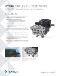
HYPRO ®<br />
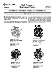
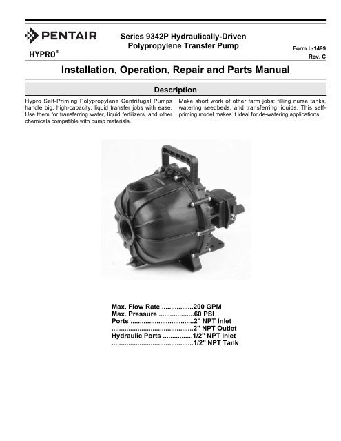
Series 9342P Hydraulically-Driven<br />
Polypropylene Transfer Pump<br />
<strong>Installation</strong>, <strong>Operation</strong>, <strong>Repair</strong> <strong>and</strong> <strong>Parts</strong> <strong>Manual</strong><br />
Description<br />
Form L-1499<br />
Rev. C<br />
Hypro Self-Priming Polypropylene Centrifugal Pumps<br />
h<strong>and</strong>le big, high-capacity, liquid transfer jobs with ease.<br />
Use them for transferring water, liquid fertilizers, <strong>and</strong> other<br />
chemicals compatible with pump materials.<br />
Make short work of other farm jobs: filling nurse tanks,<br />
watering seedbeds, <strong>and</strong> transferring liquids. This selfpriming<br />
model makes it ideal for de-watering applications.<br />
Max. Flow Rate .................200 GPM<br />
Max. Pressure ...................60 PSI<br />
Ports ..................................2" NPT Inlet<br />
............................................2" NPT Outlet<br />
Hydraulic Ports ................1/2" NPT Inlet<br />
............................................1/2" NPT Tank
General Safety Information<br />
California Proposition 65 Warning -- This product <strong>and</strong> related accessories contain chemicals known to the<br />
State of California to cause cancer, birth defects or other reproductive harm.<br />
Notes are used to notify of installation, operation, or<br />
maintenance information that is important but not<br />
safety related.<br />
Caution is used to indicate the presence of a hazard,<br />
which will or may cause minor injury or property<br />
damage if the notice is ignored<br />
Warning denotes that a potential hazard exists <strong>and</strong><br />
indicates procedures that must be followed exactly to<br />
either eliminate or reduce the hazard, <strong>and</strong> to avoid<br />
serious personal injury, or prevent future safety<br />
problems with the product.<br />
Danger is used to indicate the presence of a hazard<br />
that will result in severe personal injury, death, or<br />
property damage if the notice is ignored.<br />
Do not pump flammable or explosive fluids such as<br />
gasoline, fuel oil, kerosene, etc. Do not use in explosive<br />
atmospheres. The pump should be used only with<br />
liquids compatible with the pump component materials.<br />
Failure to follow this notice may result in severe<br />
personal injury <strong>and</strong>/or property damage <strong>and</strong> will void<br />
the product warranty.<br />
1. Do not pump at pressures higher than the<br />
maximum recommended pressure.<br />
2. Maximum liquid temperature is 140 o F.<br />
3. Disconnect power before servicing.<br />
4. Release all pressure within the system before<br />
servicing any component.<br />
5. Drain all liquids from the system before servicing<br />
any component. Flush with water.<br />
6. Secure the outlet lines before starting the pump. An<br />
unsecured line may whip, causing personal injury<br />
<strong>and</strong>/or property damage.<br />
7. Check hose for weak or worn condition before each<br />
use. Make certain that all connections are tightly<br />
secured.<br />
8. Periodically inspect the pump <strong>and</strong> the system<br />
components. Perform routine maintenance as<br />
required (See <strong>Repair</strong> Instructions).<br />
9. Use only pipe, hose <strong>and</strong> fittings rated for the<br />
maximum psi rating of the pump.<br />
10. Do not use these pumps for pumping water or other<br />
liquids for human or animal consumption.<br />
11. Do not run pump with discharge fully closed for<br />
over two minutes.<br />
Hazardous Substance Alert<br />
1. Always drain <strong>and</strong> flush pump before servicing or<br />
disassembling for any reason.<br />
2. Always drain <strong>and</strong> flush pump prior to returning unit<br />
for repair.<br />
3. Never store pumps containing hazardous<br />
chemicals.<br />
4. Before returning pump for service/repair, drain out<br />
all liquids <strong>and</strong> flush unit with neutralizing liquid.<br />
Then, drain the pump. Attach tag or include written<br />
notice certifying that this has been done. It is illegal<br />
to ship or transport any hazardous chemicals<br />
without United States Environmental Protection<br />
Agency Licensing.<br />
Never use your h<strong>and</strong> to check the condition of<br />
hydraulic lines or hoses. If hydraulic fluid penetrates<br />
the skin, get medical help immediately. Failure to get<br />
proper medical help may result in loss of limb or life.<br />
The safest way to check hydraulic lines or hoses is by<br />
holding a piece of cardboard next to the hydraulic line<br />
or hose.<br />
The sound pressure level of the Pump is 80dBA.<br />
Observe all safety precautions when operating the<br />
pump within close proximity for extended periods of<br />
time by wearing hearing protectors. Extended exposure<br />
to elevated sound levels will result in permanent loss of<br />
hearing acuteness, tinnitus, tiredness, stress, <strong>and</strong> other<br />
effects such as loss of balance <strong>and</strong> awareness.<br />
-2-
General Information—Hydraulic Systems<br />
Hydraulic Pumps<br />
Hydraulic pumps come in two basic types:<br />
• Constant displacement - which will continue to put<br />
out its rated flow regardless of pressure, until the<br />
relief valve bypasses the flow.<br />
• Variable displacement - which will produce only<br />
the flow needed by the implement until the total<br />
pump output is reached. If less than the full pump<br />
output is required, an automatic stroke control<br />
mechanism decreases the pump output to maintain<br />
a constant pressure <strong>and</strong> flow. The output varies<br />
according to dem<strong>and</strong>.<br />
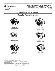
Open Center<br />
Spool Valve<br />
In Neutral<br />
Position<br />
Figure 1<br />
Spool Valves<br />
There are two basic types of spool valves used in<br />
conjunction with these pumps — Open <strong>and</strong> Closed Center.<br />
In the Open Center Valve (See Figure 1), the flow goes<br />
straight through the valve when in the neutral position. This<br />
type is used for constant displacement pumps where the<br />
flow should never be shut off.<br />
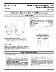
Closed Center<br />
Spool Valve<br />
In Neutral<br />
Position<br />
Figure 2<br />
The Closed Center Valve (See Figure 2) is used with<br />
variable displacement pumps. The flow is completely shut<br />
off in the neutral position, causing the pump stroke to adjust<br />
to zero flow. The flow stops, but the pump maintains a static<br />
pressure up to the valve.<br />
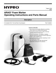
Gerotor-Type<br />
Hydraulic Motor<br />
Figure 3<br />
Three Systems<br />
Fitting these components together <strong>and</strong> installing a motor, we<br />
have one of the three types of systems: Open Center,<br />
Closed Center (pressure compensated) <strong>and</strong> Closed Center<br />
Load Sensing (flow <strong>and</strong> pressure compensated).<br />
Open Center Systems<br />
Rotor<br />
Ring<br />
Outlet<br />
Low<br />
Pressure<br />
Inner<br />
Rotor<br />
Inlet<br />
High<br />
Pressure<br />
In an Open Center System, the hydraulic pump puts out a<br />
constant flow. If the pump puts out more oil than the motor<br />
can use, a portion of the oil must be bypassed around the<br />
motor. When the oil is bypassed around a loop <strong>and</strong> does no<br />
work, the energy put into it by the pump turns into heat.<br />
Therefore, the amount of oil bypassed should be kept to a<br />
minimum. Use the largest motor possible.<br />
Closed Center (Pressure-Compensated) Systems<br />
The Closed Center Pressure-Compensated system has a<br />
variable displacement pump which will deliver flow at the<br />
necessary rate to maintain a specified pressure.<br />
Note: This pump is not configured for use with these<br />
systems.<br />
Closed Center Load Sensing Systems<br />
(Flow <strong>and</strong> Pressure-Compensating)<br />
The Closed Center Flow-Compensated System is a<br />
variation of the pressure-compensated system, designed<br />
primarily for more efficient operation <strong>and</strong> the generation of<br />
less heat. It works on the principle of maintaining a constant<br />
pressure drop from the pump to the work port of the selector<br />
valve. Any variation in dem<strong>and</strong> at the motor will cause a<br />
change in flow. The system senses this change in flow due<br />
to the change in pressure drop across the valve <strong>and</strong> causes<br />
the pump to compensate by varying the pump flow. No<br />
restrictor is used in the pressure line <strong>and</strong> no oil is bypassed.<br />
Hydraulic Motors<br />
Figure 3 shows an internal gear motor (Gerotor) where<br />
pressure causes the cavities between the gears to exp<strong>and</strong><br />
on one side, developing torque. The Gerotor type of<br />
hydraulic motor is used on Hypro pumps for its superior<br />
performance characteristics, including cooler running <strong>and</strong><br />
higher rpm capabilities.<br />
-3-
<strong>Installation</strong> Instructions<br />
All Models — Open Center Systems<br />
Models include Tank Port Adapter with built-in Check Valve<br />
Assembly <strong>and</strong> Pressure Port Adapter.<br />
Preliminary to Mounting<br />
Consult the owners manual to determine the type <strong>and</strong><br />
capacity of the hydraulic system. Make sure the hydraulic<br />
system is recommended to operate with a continuous load.<br />
Refer to the Pump Selection Guide to confirm you have the<br />
proper pump for your hydraulic system.<br />
Check to see that the pump impeller can be turned by h<strong>and</strong>.<br />
(Turn the shaft clockwise using a deep socket wrench on<br />
the impeller nut.) If it cannot be turned, open the pump<br />
casing to look for obstructions. Clean out any corrosion<br />
buildup where the casing fits over the eye of the impeller.<br />
Pump Inlet Line<br />
To achieve full capacity from the pump, the inlet line<br />
should be at least the same size as the inlet port on the<br />
pump. Reducing this line size will restrict the capabilities of<br />
the pump. The line must also be free of air leaks. Check all<br />
fittings <strong>and</strong> connections in the suction line for tightness.<br />
The introduction of air may affect the priming <strong>and</strong> pumping<br />
capabilities of the pump. Use good quality suction hose<br />
that will not be collapsed by suction.<br />
Pump Outlet Line<br />
The recommended orientation for the outlet port is pointing<br />
straight up. This allows liquid to stay in the pump while it is<br />
priming. The outlet line should be the same size as the<br />
pressure port on the pump to give the optimal flow. The<br />
line should have as few restrictions <strong>and</strong> elbows as<br />
possible to optimize the pump performance <strong>and</strong> reduce<br />
pressure drop from the pump to the discharge point.<br />
Hooking Up the Hydraulic Motor to the<br />
Tractor Hydraulic System<br />
Hypro Series 9300HMC hydraulic motor-driven pumps can<br />
be mounted on either the tractor or sprayer. When hooking<br />
up, make sure that no dirt or liquid gets into the hydraulic<br />
motor. Keep all hydraulic connections clean. The<br />
recommended filter for the hydraulic motor removes<br />
particulates greater than <strong>and</strong> including 10 microns. The >10<br />
micron filter should be placed on the return line of the<br />
hydraulic system to mitigate the risk of contaminating the oil<br />
tank. Be sure to connect the hydraulic motor into the system<br />
correctly by putting the pressure line to the pressure port<br />
adapter <strong>and</strong> return line to the tank port adapter. The port<br />
adapters on the hydraulic motor are sized to accommodate<br />
1/2" NPT fittings. For maximum performance, the hydraulic<br />
lines should also be at least 1/2" [12.7 mm] in size. For lines<br />
longer than 8 feet [2.44 m], hydraulic line size should be at<br />
least 3/4" [19.05 mm] in order to reduce heat generation.<br />
The tank (OUT) port adapter with a built-in check valve<br />
assembly will guard against reverse operation — allowing<br />
you to reverse oil flow to operate other equipment. This<br />
adapter must not be removed. St<strong>and</strong>ard spool valves,<br />
which are found on all tractor hydraulic systems, may cause<br />
potentially damaging high peak pressures in the hydraulic<br />
system when closed, because of abrupt shut-off of oil flow in<br />
both the supply <strong>and</strong> return lines. When shutting off the<br />
pump, move the selector to the FLOAT position to allow the<br />
centrifugal pump to come to a stop gradually.<br />
Priming the Pump<br />
The pump must not be run dry.<br />
Before starting the pump, the chamber needs to be filled<br />
with liquid. The pump must not be run unless it is completely<br />
filled with liquid because there is a danger of damaging the<br />
mechanical seal, which depends on the liquid for its<br />
lubrication.<br />
Self-priming models can be primed by removing the top vent<br />
plug <strong>and</strong> filling the priming chamber. The priming chamber<br />
will fill to the level of the inlet port. After use, the priming<br />
chamber should be flushed <strong>and</strong> drained to avoid chemical<br />
corrosion <strong>and</strong> damage from freezing. Drain by removing the<br />
lower drain plug.<br />
-4-
<strong>Operation</strong><br />
Open Center Systems - All Models<br />
Adjusting Centrifugal Pump Output<br />
1. Install a shut-off valve <strong>and</strong> pressure gauge on the<br />
discharge line for initial setup.<br />
2. Open the bypass adjustment screw 2-1/2 turns from<br />
fully closed. Turn the bypass screw in to achieve the<br />
flow for the desired gpm <strong>and</strong> psi.<br />
3. Start the tractor. Leave the directional valve in the<br />
neutral position <strong>and</strong> allow hydraulic oil to circulate for<br />
approximately 10 to 15 minutes or until adequately<br />
warmed.<br />
4. Prime the centrifugal pump with all valves open<br />
(See the <strong>Installation</strong> Instructions <strong>and</strong> System<br />
Configuration Diagram).<br />
5. Once the pump is primed, shut off the dischage line <strong>and</strong><br />
monitor the pressure. Shut-off pressure is not to exceed<br />
60 PSI. Adjust discharge screw accordingly.<br />
Closed Center (Load Sensing) All Models<br />
Many tractors are being introduced with load sensing<br />
systems (also referred to as flow <strong>and</strong> pressurecompensated<br />
systems) which simplify system setup <strong>and</strong><br />
eliminate many of the problems associated with using the<br />
wrong size pump motors on a given hydraulic system.<br />
Usually, any of Hypro’s 9300HMC models may be used on<br />
this type of system, provided the hydraulic system produces<br />
sufficient oil flow for the hydraulic motor being used (Refer<br />
to the Pump Selection Guide).<br />
This system maintains a constant flow of hydraulic oil for a<br />
given pressure drop. The flow is adjustable with a flow<br />
control valve installed in the hydraulic system (such as the<br />
Tortoise/Hare control on John Deere tractors). Because this<br />
system has adjustable flow, there is no need to bypass<br />
hydraulic oil as in an open center system, or to restrict the<br />
flow with orifices as in a closed center pressurecompensated<br />
system.<br />
Adjusting Centrifugal Pump Output<br />
1. Install a shut-off valve <strong>and</strong> pressure gauge on the<br />
discharge line for initial setup.<br />
2. Close <strong>and</strong> lock down the bypass adjusting screw in the<br />
hydraulic motor.<br />
3. Set the tractor hydraulic flow control valve for minimum<br />
hydraulic oil flow to the remote outlet (Tortoise position).<br />
4. Start the tractor <strong>and</strong> allow the hydraulic oil to circulate<br />
for approximately 10 to 15 minutes or until adequately<br />
warmed.<br />
5. Prime the centrifugal pump with all valves open (See<br />
the <strong>Installation</strong> Instructions <strong>and</strong> System Configuration<br />
Diagram).<br />
6. Shut off the discharge valve <strong>and</strong> monitor the pressure.<br />
Slowly adjust the tractor hydraulic flow control valve until<br />
the pump deadhead pressure approaches 60 PSI.<br />
Storage<br />
1. Drain pump. Flush pump after use.<br />
One of the most common causes for faulty pump<br />
performance is gumming or corrosion inside the pump.<br />
Flush the pump <strong>and</strong> entire system with a solution that<br />
will chemically neutralize the liquid pumped. Mix<br />
according to the manufacturer’s directions. This will<br />
dissolve most residues remaining in the pump, leaving<br />
the inside of the pump clean <strong>and</strong> ready for use.<br />
2. Store pump in a clean, dry environment.<br />
-5-
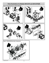
<strong>Repair</strong> Instructions<br />
Always flush pump with water or neutralizing agent before<br />
servicing.<br />
Refer to parts breakdown on Page 9 for reference<br />
numbers.<br />
PUMP HOUSING DISASSEMBLY<br />
Seal replacement requires that the pump be fully removed<br />
from the hydraulic motor. Observe carefully the disassembly<br />
process to ensure an easy assembly process. Replace all<br />
worn <strong>and</strong> eroded parts.<br />
1. Remove the 10 bolts <strong>and</strong> nuts (Ref. Nos. 2, 3, 23)<br />
holding the pump casing to the casing cover using a<br />
10mm socket <strong>and</strong> a 10mm open end wrench. Tap pump<br />
casing on the discharge port with a rubber hammer, if<br />
necessary, to break it loose from the pump flange.<br />
Remove o-ring from casing cover. Inspect parts for wear.<br />
(See Fig. 1.)<br />
Fig. 1<br />
Fig. 2<br />
2. Remove diffuser (Ref. 10) by removing the three screws<br />
(Ref. Nos. 8, 9) with a Phillips screwdriver. Inspect parts<br />
for wear. (See Fig. 2.)<br />
3. Remove impeller bolt (Ref. 11) with a 13mm wrench. Pry<br />
impeller (Ref. 12) off hydraulic motor shaft using two<br />
flathead screwdrivers. Inspect impeller <strong>and</strong> ceramic<br />
(Ref. 15) for wear. Ceramic surface must not be scuffed<br />
or cracked. To remove ceramic seal from impeller bore,<br />
use a small blade screwdriver to wedge the seal out.<br />
(See Fig. 3.)<br />
Fig. 3<br />
4. To remove mechanical seal from pump flange, first<br />
remove the pump flange from the engine by removing<br />
the four mounting bolts with a 13mm socket. From the<br />
engine side of the pump flange, press the mechanical<br />
seal out using a 1" diameter piece of PVC pipe 4" long.<br />
Inspect parts for wear. (See Figure 4.)<br />
Fig. 4<br />
5. Inspect slinger ring (Ref. 25) on hydraulic motor shaft for<br />
wear. (See Fig. 5.)<br />
Fig. 5<br />
-6-
SEAL REPLACEMENT AND<br />
PUMP HOUSING ASSEMBLY<br />
1. Install slinger ring (Ref. 25) on hydraulic motor shaft.<br />
(See Fig. 5.)<br />
2. Lubricate <strong>and</strong> install the o-ring (Ref. 16) around back<br />
side of metal portion of the seal (See Fig. 6). Insert the<br />
stationary portion of the new mechanical seal (Ref. 15)<br />
by carefully pushing only on the outer metal ring as you<br />
press it into the pump flange (Ref. 22). Use a tool with<br />
1-1/2" ID, such as 1-1/2" diameter PVC pipe, 4" long that<br />
fits over the carbon face of the seal, but pushes only on<br />
the metal ring to insert the seal. The carbon surface of<br />
the seal must be facing you during installation. Be careful<br />
to avoid scratching the seal’s carbon surface.<br />
(See Fig. 7.)<br />
3. Install washer <strong>and</strong> o-rings (Ref. 20, 21) onto the<br />
mounting bolts (Ref. 19). Apply medium strength (Blue)<br />
threadlocker onto the (4) engine mounting bolts <strong>and</strong><br />
install the pump flange (Ref. 22). Tighten the (4)<br />
mounting bolts with a 13mm socket to a torque of 10<br />
foot-pounds.<br />
4. Install the shim washer (Ref. 13) <strong>and</strong> key (Ref. 14) into<br />
the bore of the impeller (Ref. 12). Lubricate the seal<br />
cavity of the impeller with WD-40, LPS or equivalent,<br />
<strong>and</strong> carefully press the seal’s mating ceramic ring in<br />
place, seating it squarely on the bottom of the cavity.<br />
The glossy, finished side of the ceramic seal must be<br />
facing you. IMPORTANT: Make sure both seal surfaces<br />
are clean <strong>and</strong> lubricated. Never run seal surfaces dry.<br />
(See Fig. 8.)<br />
5. Install the impeller (Ref. 12) onto the hydraulic motor<br />
shaft (Ref. 26) using the bolt, washer <strong>and</strong> seal. Bolt seal<br />
must not be worn. Tighten the impeller bolt to 10 footpounds.<br />
(See Fig. 9.)<br />
6. Install flapper (Ref. 6) into diffuser (Ref. 10). Secure the<br />
perimeter of the flapper to the diffuser using the (3)<br />
Phillips head screws (Ref. 7).<br />
7. Install diffuser (Ref. 10) onto the pump flange (Ref. 22)<br />
with three Phillips head screws (Ref. Nos. 8, 9).<br />
(See Fig. 2.)<br />
8. Install the pump housing (Ref. 1) onto the pump flange<br />
(Ref. 22) <strong>and</strong> o-ring, <strong>and</strong> secure with the 10 bolts, nuts<br />
<strong>and</strong> washers, using a 10mm socket <strong>and</strong> wrench. Torque<br />
the bolts to 45-inch pounds. (See Fig. 1.)<br />
9. Assembly <strong>and</strong> inspection are now complete.<br />
Fig. 6<br />
Fig. 7<br />
Fig. 8<br />
Fig. 9<br />
-7-
Model 9342P Performance Data<br />
-8-
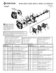
Model 9342P <strong>Parts</strong> Breakdown<br />
26<br />
23<br />
1<br />
2 3 4 5 6<br />
7<br />
8 9 10<br />
11<br />
12 13 14 17 18<br />
15 16 19 20 21 22<br />
24<br />
28 29 27<br />
25<br />
Ref. No. Torque Spec.<br />
2 45 in-lbs. / 5.1 Nm<br />
11 10 ft-lbs. / 1.1 Nm<br />
27 10 ft-lbs. / 1.1 Nm<br />
28 30<br />
7<br />
Hydraulic Oil Seal Kit No. 3430-0749<br />
Replacement Hydraulic Motors<br />
(Ref. 26) 2500-0281C & 2500-0285C<br />
include (1 ea.) Ref. 29 & 30 Port Adapters,<br />
(2) Ref. 28 O-rings, <strong>and</strong> (1) Ref. 14 Key.<br />
St<strong>and</strong>ard EPDM Seal <strong>Repair</strong> Kit 3430-0635<br />
contains: (1) Ref. 18 Diffuser Gasket, (1) Ref.<br />
17 Pump Body O-ring, (1) Ref. 16 Seal O-ring,<br />
(1) Ref. 15 Mechanical Seal, <strong>and</strong> (4) Ref. 21<br />
O-rings.<br />
Viton Seal <strong>Repair</strong> Kit 3430-0659 contains:<br />
(1) Ref. 6 Flapper Valve, (1) Ref. 15<br />
Mechanical Seal, (1) Ref. 16 Seal O-ring,<br />
(1) Ref. 17 Pump Body O-ring, (1) Ref. 18<br />
Diffuser Gasket, <strong>and</strong> (4) Ref. 21 O-rings.<br />
Pump Head Kit 3430-0691<br />
contains: all items shown above,<br />
less hydraulic motor <strong>and</strong> mounting<br />
hardware (items 1-23).<br />
Ref. Qty.<br />
No. Reqd. Part No.<br />
Description<br />
1 1 0100-1540P Pump Housing<br />
2 10 2210-0141 Bolt<br />
3 10 2270-0115 Washer<br />
4 2 1720-0230 Plug O-ring<br />
5 2 2404-0350P Fill/Drain Plug<br />
6 1 1700-0208 Flapper Valve<br />
7 3 2210-0152 Flapper Screw<br />
8 2 2210-0145 Diffuser Mounting Screw (short)<br />
9 1 2210-0144 Diffuser Mounting Screw (long)<br />
10 1 0150-1540P Diffuser<br />
11 1 2210-0142 Impeller Bolt (with washer)<br />
12 1 0401-1540P Impeller<br />
13 1 1430-0033 Shim Washer<br />
14 1 1610-0044 Key<br />
15 1 2120-0044 Mechanical Seal<br />
Ref. Qty.<br />
No. Reqd. Part No.<br />
Description<br />
16 1 1720-0231 Seal O-ring<br />
17 1 1720-0244 Pump Body O-ring<br />
18 1 1700-0209 Diffuser Gasket<br />
19 4 2210-0177 Hex Head Bolt<br />
20 4 2270-0114 Flat Washer<br />
21 4 1720-0013 O-ring<br />
22 1 0751-1540P Pump Flange<br />
23 10 2250-0087 Nut<br />
24 1 1510-0109 Motor Bracket<br />
25 1 1410-0083 Slinger Ring<br />
26 1 2500-0285C Hydraulic Motor (HM5C)<br />
26 1 2500-0281C Hydraulic Motor (HM1C)<br />
27 4 2210-0004 Mounting Bolt<br />
28 2 1720-0108 O-ring<br />
29 1 3360-0021A Pressure Port Adapter (includes o-ring)<br />
30 1 3320-0049A Tank Port Adapter (includes o-ring)<br />
-9-
Notes<br />
-10-
Notes<br />
-11-
Limited Warranty on Hypro/SHURflo Agricultural Pumps & Accessories<br />
Hypro/SHURflo (hereafter, “Hypro”) agricultural products are warranted to be free of defects in material <strong>and</strong> workmanship under<br />
normal use for the time periods listed below, with proof of purchase.<br />
- Pumps: one (1) year from the date of manufacture, or one (1) year of use. This limited warranty will not<br />
exceed two (2) years, in any event.<br />
- Accessories: ninety (90) days of use.<br />
This limited warranty will not apply to products that were improperly installed, misapplied, damaged, altered, or incompatible with<br />
fluids or components not manufactured by Hypro. All warranty considerations are governed by Hypro’s written return policy.<br />
Hypro’s obligation under this limited warranty policy is limited to the repair or replacement of the product. All returns will be tested<br />
per Hypro’s factory criteria. Products found not defective (under the terms of this limited warranty) are subject to charges paid by the<br />
returnee for the testing <strong>and</strong> packaging of “tested good” non-warranty returns.<br />
No credit or labor allowances will be given for products returned as defective. Warranty replacement will be shipped on a freight allowed<br />
basis. Hypro reserves the right to choose the method of transportation.<br />
This limited warranty is in lieu of all other warranties, expressed or implied, <strong>and</strong> no other person is authorized to give any other<br />
warranty or assume obligation or liability on Hypro’s behalf. Hypro shall not be liable for any labor, damage or other expense, nor shall<br />
Hypro be liable for any indirect, incidental or consequential damages of any kind incurred by the reason of the use or sale of<br />
any defective product. This limited warranty covers agricultural products distributed within the United States of America. Other world market<br />
areas should consult with the actual distributor for any deviation from this document.<br />
Return Procedures<br />
All products must be flushed of any chemical (ref. OSHA section 1910.1200 (d) (e) (f) (g) (h)) <strong>and</strong> hazardous chemicals must be<br />
labeled/tagged before being shipped* to Hypro for service or warranty consideration. Hypro reserves the right to request a Material Safety<br />
Data Sheet from the returnee for any pump/product it deems necessary. Hypro reserves the right to “disposition as scrap” products returned<br />
which contain unknown fluids. Hypro reserves the right to charge the returnee for any <strong>and</strong> all costs incurred for chemical testing, <strong>and</strong> proper<br />
disposal of components containing unknown fluids. Hypro requests this in order to protect the environment <strong>and</strong> personnel from the hazards<br />
of h<strong>and</strong>ling unknown fluids.<br />
Be prepared to give Hypro full details of the problem, including the model number, date of purchase, <strong>and</strong> from whom you purchased your<br />
product. Hypro may request additional information, <strong>and</strong> may require a sketch to illustrate the problem.<br />
Contact Hypro Service Department at 800-468-3428 to receive a Return Merch<strong>and</strong>ise Authorization number (RMA#).<br />
Returns are to be shipped with the RMA number clearly marked on the outside of the package. Hypro shall not be liable for freight damage<br />
incurred during shipping. Please package all returns carefully. All products returned for warranty work should be sent shipping charges<br />
prepaid to:<br />
HYPRO / PENTAIR<br />
Attention: Service Department<br />
375 Fifth Avenue NW<br />
New Brighton, MN 55112<br />
For technical or application assistance, call the Hypro Technical/Application number: 800-445-8360, or send an email to:<br />
technical@hypropumps.com. To obtain service or warranty assistance, call the Hypro Service <strong>and</strong> Warranty number: 800-468-3428;<br />
or send a fax to the Hypro Service <strong>and</strong> Warranty FAX: 651-766-6618.<br />
*Carriers, including U.S.P.S., airlines, UPS, ground freight, etc., require specific identification of any hazardous material being shipped. Failure to do so may<br />
result in a substantial fine <strong>and</strong>/or prison term. Check with your shipping company for specific instructions.<br />
Note: This warranty does not apply to Hypro Pump Kit 3430-0637. This<br />
is because the user could incorrectly assemble the parts <strong>and</strong> cause the<br />
pump to work improperly.<br />
Visit www.hypropumps.com/register today to register<br />
your product <strong>and</strong> stay up-to-date on new products<br />
<strong>and</strong> promotional offers.<br />
The following information is required:<br />
Model # _______________ Serial # _______________<br />
Hypro (5/13)<br />
Printed in USA<br />
375 Fifth Avenue NW • New Brighton, MN 55112 USA<br />
Phone: (651) 766-6300 • 800-424-9776 • Fax: 800-323-6496<br />
www.hypropumps.com