Propositional Argumentation Systems and Symbolic Evidence Theory
Propositional Argumentation Systems and Symbolic Evidence Theory
Propositional Argumentation Systems and Symbolic Evidence Theory

You also want an ePaper? Increase the reach of your titles
YUMPU automatically turns print PDFs into web optimized ePapers that Google loves.
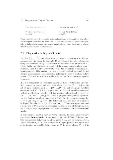
7.2 Diagnostics in Digital Circuits 107<br />
(a2 <strong>and</strong> a6 <strong>and</strong> a12) (a4 <strong>and</strong> a6 <strong>and</strong> a11)<br />
? (dsp tuberculosis) ? (dsp bronchitis)<br />
0.1924 0.5857<br />
From symbolic support the doctor gets configurations of assumptions that allow<br />
him to explain or deduce the hypothesis. In contrast, numerical degrees of support<br />
help to judge <strong>and</strong> compare the results quantitatively. Here, bronchitis is almost<br />
three times as credible as tuberculosis.<br />
7.2 Diagnostics in Digital Circuits<br />
Let S = {C 1 , . . . , C n } describe a technical system consisting of n different<br />
components. As shown in Example 3.2 of Section 3.2, such systems can<br />
easily be described using the formalism of symbolic hints (Kohlas et al.,<br />
1995). In the case of digital circuits, i.e. if the system consists only of binary<br />
variables, then it is also appropriate to use the formalism of assumption–<br />
based systems. This section proposes a general method to model digital<br />
circuits as assumption–based systems, including the case of multiple failure<br />
modes. The aim is to find possible explanations for an incorrect system<br />
behaviour.<br />
If C is a component of a technical system S, then it determines the relation<br />
between its input– <strong>and</strong> output–variables. Let I = {I 1 , . . . , I r } be the<br />
set of input–variables <strong>and</strong> O = {O 1 , . . . , O s } the set of output–variables<br />
connected with C. If S is a digital circuit, then all variables connected<br />
with C are Boolean variables with two possible values 0 <strong>and</strong> 1. Let P =<br />
{in 1 , . . . , in r , out 1 , . . . , out s } be the set of propositional symbols representing<br />
the Boolean variables connected with C. in 1 , for example, st<strong>and</strong>s for<br />
I 1 = 1 <strong>and</strong> ∼in 1 for I 1 = 0. The behaviour of C can then be expressed<br />
as logical formula m 0 ∈ L P . For example, if C has two inputs <strong>and</strong> one<br />
output, <strong>and</strong> if C is a module producing the logical <strong>and</strong> of its inputs, then<br />
m 0 = out 1 ↔ in 1 ∧ in 2 represents the correct behaviour of C called normal<br />
mode.<br />
A component C possibly may not work correctly. In such a case, we have<br />
a so–called failure mode. A component may have different failure modes.<br />
The component’s behaviour in failure mode i can also be expressed by a<br />
logical formula m i ∈ L P . For example, let C again produce the logical <strong>and</strong><br />
of its inputs. A possible failure mode of C, in which always O 1 = 0 is