Mi Distribution boards - IC SYSTEMS automatika
Mi Distribution boards - IC SYSTEMS automatika
Mi Distribution boards - IC SYSTEMS automatika

You also want an ePaper? Increase the reach of your titles
YUMPU automatically turns print PDFs into web optimized ePapers that Google loves.
<strong>Mi</strong> <strong>Distribution</strong> <strong>boards</strong> <br />
Technics<br />
HENPAS<br />
MC<br />
<strong>Mi</strong><br />
KV<br />
DK<br />
Service<br />
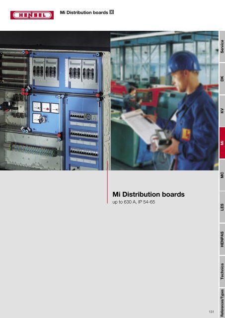
<strong>Mi</strong> <strong>Distribution</strong> <strong>boards</strong><br />
up to 630 A, IP 54-65<br />
LES<br />
131<br />
References/Types
Service<br />
DK<br />
<strong>Mi</strong><br />
MC<br />
LES<br />
Technics<br />
<strong>Mi</strong> <strong>Distribution</strong> <strong>boards</strong> <br />
Contents<br />
System benefits / system configuration pages 134 - 135<br />
<strong>Mi</strong> Empty boxes<br />
with transparent lids pages 136 - 137<br />
with opaque lid pages 138 - 139<br />
KV<br />
<strong>Mi</strong> Circuit breaker boxes<br />
12 - 48 modules pages 140, 142<br />
12 - 48 modules with hinged flaps pages 141, 142<br />
for miniature circuit-breakers (MCB) page 143<br />
<strong>Mi</strong> KWH meter boxes pages 144 - 146<br />
<strong>Mi</strong> Busbar boxes<br />
page 147<br />
HENPAS<br />
<strong>Mi</strong> Isolator boxes<br />
with built-in switch disconnectors in accordance with EN 60 947-3 pages 148 - 150<br />
References/Types<br />
132
<strong>Mi</strong> <strong>Distribution</strong> <strong>boards</strong> <br />
Contents<br />
<strong>Mi</strong> MCCB Circuit-breaker boxes<br />
with circuit-breaker (MCCB) in accordance with EN 60 947-2 pages 151 - 152<br />
Technics<br />
HENPAS<br />
Service<br />
<strong>Mi</strong><br />
LES<br />
MC<br />
KV<br />
DK<br />
Accessories pages 153 - 171<br />
Technical details pages 172 - 184<br />
For additional information and planning assistance<br />
refer to index HENPAS or to the internet:<br />
www.hensel-electric.de<br />
133<br />
References/Types
LES<br />
HENPAS<br />
<strong>Mi</strong> <strong>Distribution</strong> <strong>boards</strong> <br />
System benefits<br />
Service<br />
Insulation-enclosed, totally insulated,<br />
modular box system<br />
for the assembly of type-tested low-voltage switchgear<br />
assemblies up to 630 A<br />
in accordance with EN 60 439-1<br />
Boxes can also be used as a single box<br />
Degree of protection IP 65: dust-proof and jet water-proof<br />
DK<br />
Application area: suitable for indoor and outdoor installation, protected<br />
against weather influences<br />
Material: high-quality thermoplastics polycarbonate<br />
Burning behaviour: Glow wire test in accordance with IEC 60 695-2-1,<br />
self-extinguishing, flame-retardant<br />
silicone- und halogen-free<br />
KV<br />
<strong>Mi</strong> combination example<br />
Chemical resistance towards acid, lye, benzine and mineral oil<br />
Box system: functional boxes with standardised kits up to 630 A<br />
Protection covers made of high-quality thermoplastics polycarbonate<br />
Protection covers with protected and captive labelling strips<br />
<strong>Mi</strong><br />
Electrical devices to be manually actuated and bus-mounted switchgear<br />
with protection cover<br />
As standard main busbar system with N/PEN conductor in the area of<br />
phase conductors and N conductor with the same current carrying capacity<br />
as the phase conductors<br />
Mounting plates for device mounting<br />
Large wall openings enable the wiring within the distribution <strong>boards</strong><br />
MC<br />
Degree of protection IP 65 dust-proof and<br />
jet water-proof.<br />
Cable entry via metric knockouts in all box walls,<br />
via flanges with metric knockouts or elastic membranes<br />
or cable inserts with up to 74 mm cable diameter<br />
Wall fixing right away in the boxes,<br />
via external brackets or via mounting profiles<br />
Facility for lead seal and locking<br />
Technics<br />
References/Types<br />
As standard main busbar system EMC-compliant,<br />
with N/PEN conductor in the area of phase<br />
conductors and with the same current carrying<br />
capacity as the phase conductors.<br />
134
<strong>Mi</strong> <strong>Distribution</strong> <strong>boards</strong> <br />
System configuration<br />
Structure of types of <strong>Mi</strong> distribution <strong>boards</strong>:<br />
0<br />
The 1st figure indicates the<br />
box function<br />
<strong>Mi</strong> Empty box<br />
<strong>Mi</strong> 1 2 3 4<br />
The 3rd and 4th figure indicate the components<br />
or the consecutive numbering<br />
Service<br />
1<br />
<strong>Mi</strong> Circuit breaker box<br />
The 2nd figure<br />
indicates the size of boxes<br />
<strong>Mi</strong><br />
KV<br />
DK<br />
2<br />
<strong>Mi</strong> KWH meter box<br />
3<br />
<strong>Mi</strong> screw-type fuse boxes,<br />
diazed or neozed<br />
4<br />
<strong>Mi</strong> HRC fuse boxes,<br />
sizes HRC 00, HRC 1, HRC 2,<br />
HRC 3, 3-pole<br />
5<br />
<strong>Mi</strong> HRC fuse boxes with fuse<br />
switch disconnector,<br />
sizes HRC 00, HRC 1,<br />
HRC 2, HRC 3, 3-pole<br />
MC<br />
6<br />
<strong>Mi</strong> HRC fuse boxes on busbars,<br />
<strong>Mi</strong> HRC fuse boxes with fuse switch<br />
disconnector with busbars,<br />
<strong>Mi</strong> busbar boxes up to 630 A<br />
LES<br />
7<br />
<strong>Mi</strong> isolator boxes,<br />
<strong>Mi</strong> MCCB circuit-breaker boxes<br />
with thermal and magnetic<br />
release up to 630 A<br />
HENPAS<br />
8<br />
<strong>Mi</strong> main line distribution board<br />
Technics<br />
135<br />
References/Types
KV<br />
<strong>Mi</strong><br />
<strong>Mi</strong> <strong>Distribution</strong> <strong>boards</strong> <br />
Empty boxes<br />
with transparent lid<br />
Service<br />
material high-quality polycarbonate<br />
colour grey, RAL 7032<br />
degree of protection IP 65<br />
<strong>Mi</strong> 0100 box size 1 <br />
<br />
max. installation depth<br />
with built-in mounting plate 146 mm<br />
<br />
with built-in DIN rail 135 mm<br />
lid fasteners for tool operation<br />
sealable<br />
please order mounting rails or mounting plates<br />
additionally<br />
<br />
<br />
<br />
<br />
DK<br />
<strong>Mi</strong> 0200 box size 2 <br />
<br />
max. installation depth<br />
with built-in mounting plate 146 mm<br />
<br />
with built-in DIN rail 135 mm<br />
<br />
<br />
<br />
<br />
<strong>Mi</strong> 0210 box size 2 <br />
<br />
max. installation depth<br />
with built-in mounting plate 191 mm<br />
<br />
with built-in DIN rail 180 mm<br />
<br />
<br />
<br />
<br />
MC<br />
<strong>Mi</strong> 0220 box size 2<br />
<br />
max. installation depth<br />
with built-in mounting plate 115 mm<br />
<br />
<br />
with built-in DIN rail 104 mm<br />
with hinged lid for built-in equipment<br />
with protection cover which must be<br />
operated<br />
<br />
<br />
<br />
<br />
<br />
<br />
<br />
LES<br />
<strong>Mi</strong> 0300 box size 3 <br />
<br />
max. installation depth<br />
with built-in mounting plate 146 mm<br />
<br />
with built-in DIN rail 135 mm<br />
<br />
<br />
<br />
<br />
HENPAS<br />
<strong>Mi</strong> 0310 box size 3 <br />
<br />
max. installation depth<br />
with built-in mounting plate 191 mm<br />
<br />
with built-in DIN rail 180 mm<br />
<br />
<br />
<br />
<br />
Technics<br />
Box walls with metric cable entry:<br />
References/Types<br />
136<br />
Wall 1 Wall 2 Wall 3 Wall 4 Wall 5<br />
1 x M 20 2 x M 20 4 x M 25 1 x M 20 8 x M 32<br />
1 x M 32/40 10 x M 25 3 x M 40/50 4 x M 25 4 x M 40/50<br />
1 x M 32/40 1 x M 32/40<br />
3 x M 40/50
<strong>Mi</strong> <strong>Distribution</strong> <strong>boards</strong> <br />
Empty boxes<br />
with transparent lid<br />
material high-quality polycarbonate<br />
colour grey, RAL 7032<br />
degree of protection IP 65<br />
<strong>Mi</strong> 0400 box size 4 <br />
<br />
max. installation depth<br />
with built-in mounting plate 146 mm<br />
<br />
with built-in DIN rail 135 mm<br />
lid fasteners for tool operation<br />
sealable<br />
please order mounting rails or mounting plates<br />
additionally<br />
<br />
<br />
<br />
HENPAS<br />
Service<br />
LES<br />
KV<br />
<strong>Mi</strong><br />
DK<br />
<br />
<strong>Mi</strong> 0410 box size 4 <br />
<br />
max. installation depth<br />
with built-in mounting plate 191 mm<br />
<br />
with built-in DIN rail 180 mm<br />
<br />
<br />
<br />
<br />
<strong>Mi</strong> 0800 box size 8<br />
<br />
<br />
max. installation depth<br />
with built-in mounting plate 146 mm<br />
with built-in DIN rail 135 mm<br />
cable entry only possible via flange<br />
<br />
MC<br />
Box walls with metric cable entry:<br />
Technics<br />
Wall 1 Wall 2 Wall 3 Wall 4 Wall 5<br />
1 x M 20 2 x M 20 4 x M 25 1 x M 20 8 x M 32<br />
1 x M 32/40 10 x M 25 3 x M 40/50 4 x M 25 4 x M 40/50<br />
1 x M 32/40 1 x M 32/40<br />
3 x M 40/50<br />
137<br />
References/Types
KV<br />
<strong>Mi</strong><br />
<strong>Mi</strong> <strong>Distribution</strong> <strong>boards</strong> <br />
Empty boxes<br />
with opaque lid<br />
Service<br />
material high-quality polycarbonate<br />
colour grey, RAL 7032<br />
degree of protection IP 65<br />
<strong>Mi</strong> 0101 box size 1 <br />
<br />
max. installation depth<br />
with built-in mounting plate 146 mm<br />
<br />
with built-in DIN rail 135 mm<br />
lid fasteners for tool operation<br />
sealable<br />
please order mounting rails or mounting plates<br />
additionally<br />
<br />
<br />
<br />
<br />
DK<br />
<strong>Mi</strong> 0201 box size 2 <br />
<br />
max. installation depth<br />
with built-in mounting plate 146 mm<br />
<br />
with built-in DIN rail 135 mm<br />
<br />
<br />
<br />
<br />
<strong>Mi</strong> 0211 box size 2 <br />
<br />
max. installation depth<br />
with built-in mounting plate 191 mm<br />
<br />
with built-in DIN rail 180 mm<br />
<br />
<br />
<br />
<br />
MC<br />
<strong>Mi</strong> 0221 box size 2<br />
<br />
max. installation depth<br />
with built-in mounting plate 115 mm<br />
<br />
<br />
with built-in DIN rail 104 mm<br />
with hinged lid for built-in equipment<br />
with protection cover which must be<br />
operated<br />
<br />
<br />
<br />
<br />
<br />
<br />
<br />
LES<br />
<strong>Mi</strong> 0301 box size 3 <br />
<br />
max. installation depth<br />
with built-in mounting plate 146 mm<br />
<br />
with built-in DIN rail 135 mm<br />
<br />
<br />
<br />
<br />
HENPAS<br />
<strong>Mi</strong> 0311 box size 3 <br />
<br />
max. installation depth<br />
with built-in mounting plate 191 mm<br />
<br />
with built-in DIN rail 180 mm<br />
<br />
<br />
<br />
<br />
Technics<br />
Box walls with metric cable entry:<br />
References/Types<br />
138<br />
Wall 1 Wall 2 Wall 3 Wall 4 Wall 5<br />
1 x M 20 2 x M 20 4 x M 25 1 x M 20 8 x M 32<br />
1 x M 32/40 10 x M 25 3 x M 40/50 4 x M 25 4 x M 40/50<br />
1 x M 32/40 1 x M 32/40<br />
3 x M 40/50
<strong>Mi</strong> <strong>Distribution</strong> <strong>boards</strong> <br />
Empty boxes<br />
with opaque lid<br />
material high-quality polycarbonate<br />
colour grey, RAL 7032<br />
degree of protection IP 65<br />
<strong>Mi</strong> 0401 box size 4 <br />
<br />
max. installation depth<br />
with built-in mounting plate 146 mm<br />
<br />
with built-in DIN rail 135 mm<br />
lid fasteners for tool operation<br />
sealable<br />
please order mounting rails or mounting plates<br />
additionally<br />
<br />
<br />
<br />
HENPAS<br />
Service<br />
LES<br />
KV<br />
<strong>Mi</strong><br />
DK<br />
<br />
<strong>Mi</strong> 0411 box size 4 <br />
<br />
max. installation depth<br />
with built-in mounting plate 191 mm<br />
<br />
with built-in DIN rail 180 mm<br />
<br />
<br />
<br />
<br />
<strong>Mi</strong> 0801 box size 8<br />
<br />
<br />
max. installation depth<br />
with built-in mounting plate 146 mm<br />
with built-in DIN rail 135 mm<br />
cable entry only possible via flange<br />
<br />
MC<br />
Box walls with metric cable entry:<br />
Technics<br />
Wall 1 Wall 2 Wall 3 Wall 4 Wall 5<br />
1 x M 20 2 x M 20 4 x M 25 1 x M 20 8 x M 32<br />
1 x M 32/40 10 x M 25 3 x M 40/50 4 x M 25 4 x M 40/50<br />
1 x M 32/40 1 x M 32/40<br />
3 x M 40/50<br />
139<br />
References/Types
<strong>Mi</strong> <strong>Distribution</strong> <strong>boards</strong> <br />
Circuit-breaker boxes<br />
for installation of DIN rail equipment in accordance with DIN 43 880<br />
Service<br />
material high-quality polycarbonate<br />
colour grey, RAL 7032<br />
degree of protection IP 65<br />
lid fasteners for manual operation<br />
with blanking strips for unused DIN rail openings<br />
DK<br />
<strong>Mi</strong> 1112 12 modules, 1 x 12 x 18 mm<br />
<br />
1-row<br />
with PE and N terminal for copper<br />
<br />
<br />
conductors, screw-type terminal<br />
per PE/N number x cross-section<br />
10 x 16 mm², Cu<br />
<br />
<br />
<br />
<br />
<br />
KV<br />
<strong>Mi</strong> 1224 24 modules, 2 x 12 x 18 mm<br />
<br />
2-row<br />
FIXCONNECT plug-in technology<br />
<br />
<br />
for PE/N<br />
per PE/N number x cross-section<br />
3 x 25 mm², Cu<br />
12 x 4 mm², Cu<br />
<br />
<br />
<br />
<br />
<br />
<strong>Mi</strong><br />
<strong>Mi</strong> 1220 24 modules, 2 x 12 x 18 mm<br />
<br />
2-row<br />
with hinged lid<br />
<br />
<br />
FIXCONNECT plug-in technology<br />
for PE/N<br />
per PE/N number x cross-section<br />
3 x 25 mm², Cu<br />
12 x 4 mm², Cu<br />
<br />
<br />
<br />
<br />
<br />
MC<br />
<strong>Mi</strong> 1336 36 modules, 3 x 12 x 18 mm<br />
<br />
3-row<br />
FIXCONNECT plug-in technology<br />
<br />
<br />
for PE/N<br />
per PE/N number x cross-section<br />
6 x 25 mm², Cu<br />
24 x 4 mm², Cu<br />
<br />
<br />
<br />
<br />
<br />
<br />
LES<br />
HENPAS<br />
<strong>Mi</strong> 1448 48 modules, 4 x 12 x 18 mm<br />
<br />
4-row<br />
FIXCONNECT plug-in technology<br />
<br />
<br />
for PE/N<br />
per PE/N number x cross-section<br />
6 x 25 mm², Cu<br />
24 x 4 mm², Cu<br />
<br />
<br />
<br />
<br />
<br />
<br />
Technics<br />
Box walls with metric cable entry:<br />
References/Types<br />
140<br />
Wall 1 Wall 2 Wall 3 Wall 4 Wall 5<br />
1 x M 20 2 x M 20 4 x M 25 1 x M 20 8 x M 32<br />
1 x M 32/40 10 x M 25 3 x M 40/50 4 x M 25 4 x M 40/50<br />
1 x M 32/40 1 x M 32/40<br />
3 x M 40/50
<strong>Mi</strong> <strong>Distribution</strong> <strong>boards</strong> <br />
Circuit-breaker boxes<br />
for installation of DIN rail equipment in accordance with DIN 43 880<br />
material high-quality polycarbonate<br />
colour grey, RAL 7032<br />
degree of protection IP 65<br />
with hinged flaps<br />
lid fasteners for manual operation<br />
with blanking strips for unused DIN rail openings<br />
Service<br />
<strong>Mi</strong> 1111 12 modules, 1 x 12 x 18 mm<br />
<br />
1-row<br />
with PE and N terminal for copper<br />
<br />
<br />
conductors, screw-type terminal<br />
per PE/N number x cross-section<br />
10 x 16 mm², Cu<br />
<br />
<br />
<br />
<br />
<br />
DK<br />
<strong>Mi</strong> 1222 24 modules, 2 x 12 x 18 mm<br />
<br />
2-row<br />
FIXCONNECT plug-in technology<br />
<br />
<br />
for PE/N<br />
per PE/N number x cross-section<br />
3 x 25 mm², Cu<br />
12 x 4 mm², Cu<br />
<br />
<br />
<br />
<br />
<br />
KV<br />
<strong>Mi</strong> 1333 36 modules, 3 x 12 x 18 mm<br />
<br />
3-row<br />
FIXCONNECT plug-in technology<br />
<br />
<br />
for PE/N<br />
per PE/N number x cross-section<br />
6 x 25 mm², Cu<br />
24 x 4 mm², Cu<br />
<br />
<br />
<br />
<br />
<br />
<br />
<strong>Mi</strong><br />
<strong>Mi</strong> 1444 48 modules, 4 x 12 x 18 mm<br />
<br />
4-row<br />
FIXCONNECT plug-in technology<br />
<br />
<br />
for PE/N<br />
per PE/N number x cross-section<br />
6 x 25 mm², Cu<br />
24 x 4 mm², Cu<br />
<br />
MC<br />
HENPAS<br />
LES<br />
<br />
<br />
<br />
<br />
<br />
Box walls with metric cable entry:<br />
Technics<br />
Wall 1 Wall 2 Wall 3 Wall 4 Wall 5<br />
1 x M 20 2 x M 20 4 x M 25 1 x M 20 8 x M 32<br />
1 x M 32/40 10 x M 25 3 x M 40/50 4 x M 25 4 x M 40/50<br />
1 x M 32/40 1 x M 32/40<br />
3 x M 40/50<br />
141<br />
References/Types
<strong>Mi</strong><br />
MC<br />
LES<br />
HENPAS<br />
<strong>Mi</strong> <strong>Distribution</strong> <strong>boards</strong> <br />
Circuit-breaker boxes<br />
for installation of DIN rail equipment in accordance with DIN 43 880<br />
Service<br />
material high-quality polycarbonate<br />
colour grey, RAL 7032<br />
degree of protection IP 65<br />
without PE and N terminal<br />
lid fasteners for manual operation<br />
with blanking strips for unused DIN rail openings<br />
with 1 DIN rail 284 mm wide (for installation<br />
depth of 72 mm)<br />
<strong>Mi</strong> 1440 36 modules, 3 x 12 x 18 mm <br />
<br />
4-row<br />
<br />
<br />
<br />
<br />
DK<br />
KV<br />
<br />
<strong>Mi</strong> 1443 36 modules, 3 x 12 x 18 mm <br />
<br />
4-row<br />
with 3 hinged flaps<br />
<br />
<br />
<br />
<br />
<br />
Technics<br />
Box walls with metric cable entry:<br />
References/Types<br />
142<br />
Wall 1 Wall 2 Wall 3 Wall 4 Wall 5<br />
1 x M 20 2 x M 20 4 x M 25 1 x M 20 8 x M 32<br />
1 x M 32/40 10 x M 25 3 x M 40/50 4 x M 25 4 x M 40/50<br />
1 x M 32/40 1 x M 32/40<br />
3 x M 40/50
<strong>Mi</strong> <strong>Distribution</strong> <strong>boards</strong> <br />
Circuit-breaker boxes<br />
for miniature circuit-breakers (MCB)<br />
material high-quality polycarbonate<br />
colour grey, RAL 7032<br />
degree of protection IP 65<br />
lid fasteners for manual operation<br />
with 1-pole main branch terminal<br />
protection cover can be sealed, with lockable<br />
blanking strip<br />
Service<br />
<strong>Mi</strong> 1281 6 modules, 1 x 6 x 18 mm <br />
<br />
1-row<br />
PEN number and cross-section<br />
<br />
1 x 25 mm 2 , 2 x 16 mm 2 , Cu<br />
<br />
<br />
<br />
<br />
HENPAS<br />
LES<br />
Technics<br />
MC<br />
<strong>Mi</strong><br />
KV<br />
DK<br />
Box walls with metric cable entry:<br />
Wall 1 Wall 2 Wall 3 Wall 4 Wall 5<br />
1 x M 20 2 x M 20 4 x M 25 1 x M 20 8 x M 32<br />
1 x M 32/40 10 x M 25 3 x M 40/50 4 x M 25 4 x M 40/50<br />
1 x M 32/40 1 x M 32/40<br />
3 x M 40/50<br />
143<br />
References/Types
DK<br />
MC<br />
<strong>Mi</strong> <strong>Distribution</strong> <strong>boards</strong> <br />
KWH meter boxes<br />
Service<br />
material high-quality polycarbonate<br />
colour grey, RAL 7032<br />
degree of protection IP 65<br />
with built-in KWH meter support and meter<br />
fixing screws<br />
lid fasteners for tool operation<br />
can be sealed twice<br />
use in unmetered area after consultation<br />
with local VNB<br />
<strong>Mi</strong> 2200 <br />
<br />
max. installation depth 146 mm<br />
<br />
<br />
<br />
<br />
<br />
<strong>Mi</strong> 2300 <br />
<br />
max. installation depth 146 mm<br />
<br />
<br />
<br />
<br />
LES<br />
KV<br />
<br />
<strong>Mi</strong><br />
<strong>Mi</strong> 2310 <br />
<br />
max. installation depth 190 mm<br />
<br />
<br />
<br />
<br />
<br />
<strong>Mi</strong> 2400 <br />
<br />
max. installation depth 146 mm<br />
with additional DIN rail<br />
<br />
<br />
<br />
<br />
HENPAS<br />
<br />
<strong>Mi</strong> 2410 <br />
<br />
max. installation depth 190 mm<br />
with additional DIN rail<br />
<br />
<br />
<br />
<br />
Technics<br />
Box walls with metric cable entry:<br />
<br />
References/Types<br />
144<br />
Wall 1 Wall 2 Wall 3 Wall 4 Wall 5<br />
1 x M 20 2 x M 20 4 x M 25 1 x M 20 8 x M 32<br />
1 x M 32/40 10 x M 25 3 x M 40/50 4 x M 25 4 x M 40/50<br />
1 x M 32/40 1 x M 32/40<br />
3 x M 40/50
<strong>Mi</strong> <strong>Distribution</strong> <strong>boards</strong> <br />
KWH meter boxes<br />
material high-quality polycarbonate<br />
colour grey, RAL 7032<br />
with built-in KWH meter support and meter<br />
fixing screws<br />
lid fasteners for tool operation<br />
can be sealed twice<br />
Service<br />
<strong>Mi</strong> 2411<br />
<br />
max. installation depth 190 mm<br />
with additional DIN rail<br />
<br />
<br />
with hinged flap, sealable<br />
standard opening dimensions<br />
140 x 240 mm<br />
for maximum KWH meters, time switches etc.<br />
degree of protection IP 54<br />
<br />
<br />
<br />
<br />
DK<br />
<strong>Mi</strong><br />
HENPAS<br />
MC<br />
LES<br />
KV<br />
<strong>Mi</strong> 2413<br />
<br />
max. installation depth 190 mm<br />
without DIN rail<br />
<br />
<br />
with KWH meter window flap, sealable<br />
standard opening dimensions<br />
140 x 310 mm<br />
for tool or manual operation<br />
for maximum KWH meters, time switches etc.<br />
for padlock (clip Ø max. 6 mm)<br />
degree of protection IP 54<br />
<br />
<br />
<br />
<br />
<strong>Mi</strong> 2420<br />
<br />
max. installation depth 146 mm<br />
hinged flap with protection cover for<br />
<br />
<br />
12 modules (1 x 12 x 18 mm)<br />
and associated DIN rail<br />
degree of protection IP 65<br />
<br />
<br />
<br />
<br />
Box walls with metric cable entry:<br />
Technics<br />
Wall 1 Wall 2 Wall 3 Wall 4 Wall 5<br />
1 x M 20 2 x M 20 4 x M 25 1 x M 20 8 x M 32<br />
1 x M 32/40 10 x M 25 3 x M 40/50 4 x M 25 4 x M 40/50<br />
1 x M 32/40 1 x M 32/40<br />
3 x M 40/50<br />
145<br />
References/Types
<strong>Mi</strong><br />
MC<br />
LES<br />
HENPAS<br />
<strong>Mi</strong> <strong>Distribution</strong> <strong>boards</strong> <br />
KWH meter boxes<br />
Service<br />
material high-quality polycarbonate<br />
colour grey, RAL 7032<br />
degree of protection IP 65<br />
with built-in KWH meter support and meter<br />
fixing screws<br />
lid fasteners for tool operation<br />
can be sealed twice<br />
<strong>Mi</strong> 2800<br />
<br />
<br />
DK<br />
max. installation depth 146 mm<br />
with additional DIN rail<br />
cable entry only possible via flange<br />
<br />
KV<br />
<strong>Mi</strong> 2820<br />
<br />
<br />
max. installation depth 146 mm<br />
hinged flap with protection cover for<br />
12 modules (1 x 12 x 18 mm)<br />
and associated DIN rail<br />
cable entry only possible via flange<br />
<br />
Technics<br />
Box walls with metric cable entry:<br />
References/Types<br />
146<br />
Wall 1 Wall 2 Wall 3 Wall 4 Wall 5<br />
1 x M 20 2 x M 20 4 x M 25 1 x M 20 8 x M 32<br />
1 x M 32/40 10 x M 25 3 x M 40/50 4 x M 25 4 x M 40/50<br />
1 x M 32/40 1 x M 32/40<br />
3 x M 40/50
<strong>Mi</strong> <strong>Distribution</strong> <strong>boards</strong> <br />
Busbar boxes<br />
for combination with <strong>Mi</strong> boxes<br />
material high-quality polycarbonate<br />
colour grey, RAL 7032<br />
degree of protection IP 65<br />
5-pole<br />
lid fasteners for tool operation<br />
sealable<br />
without feed-in terminals<br />
N conductor with the same current carrying<br />
capacity as the phase conductors<br />
Service<br />
<strong>Mi</strong> 6252<br />
<strong>Mi</strong> 6255<br />
<strong>Mi</strong> 6256<br />
busbar rated current 250 A<br />
busbar rated current 400 A<br />
busbar rated current 630 A<br />
<br />
<br />
<br />
<br />
<br />
<br />
<br />
<br />
<br />
DK<br />
<strong>Mi</strong> 6452<br />
<strong>Mi</strong> 6455<br />
<strong>Mi</strong> 6456<br />
busbar rated current 250 A<br />
busbar rated current 400 A<br />
busbar rated current 630 A<br />
<br />
<br />
<br />
<br />
<br />
<br />
<br />
<br />
<br />
KV<br />
<strong>Mi</strong> 6352<br />
<strong>Mi</strong> 6355<br />
<strong>Mi</strong> 6356<br />
as feeder box<br />
busbar rated current 250 A<br />
busbar rated current 400 A<br />
busbar rated current 630 A<br />
<br />
<br />
<br />
<br />
<br />
<br />
<br />
<br />
<br />
<strong>Mi</strong><br />
<strong>Mi</strong> 6457<br />
<strong>Mi</strong> 6458<br />
<strong>Mi</strong> 6459<br />
as feeder box<br />
busbar rated current 250 A<br />
busbar rated current 400 A<br />
busbar rated current 630 A<br />
<br />
<br />
<br />
<br />
<br />
<br />
<br />
<br />
<br />
MC<br />
LES<br />
<strong>Mi</strong> 6856<br />
as feeder box<br />
busbar rated current 630 A<br />
<br />
<br />
HENPAS<br />
<br />
Box walls with metric cable entry:<br />
Technics<br />
Wall 1 Wall 2 Wall 3 Wall 4 Wall 5<br />
1 x M 20 2 x M 20 4 x M 25 1 x M 20 8 x M 32<br />
1 x M 32/40 10 x M 25 3 x M 40/50 4 x M 25 4 x M 40/50<br />
1 x M 32/40 1 x M 32/40<br />
3 x M 40/50<br />
147<br />
References/Types
HENPAS<br />
<strong>Mi</strong> <strong>Distribution</strong> <strong>boards</strong> <br />
<strong>Mi</strong> isolator boxes<br />
with built-in switch disconnectors in accordance with EN 60 947-3<br />
Service<br />
material high-quality polycarbonate<br />
colour grey RAL 7032<br />
degree of protection IP 65<br />
lid fasteners for tool operation<br />
sealable<br />
with PE and N terminals for copper conductors<br />
lockable handle<br />
DK<br />
<strong>Mi</strong> 7106 63 A <br />
<br />
3-pole + PE + N<br />
<br />
connection 35 mm², Cu or <strong>Mi</strong> VS 100<br />
switching capacity AC 23 A/B 400V 30 kW<br />
maximum back-up fuse 80 A<br />
rated voltage AC 690 V<br />
<br />
<br />
<br />
<br />
KV<br />
<strong>Mi</strong> 7210 100 A <br />
<br />
3-pole + PE + N<br />
<br />
connection 35 mm², Cu or <strong>Mi</strong> VS 100<br />
switching capacity AC 23 A/B 400V 37 kW<br />
maximum back-up fuse 100 A<br />
rated voltage AC 690 V<br />
<br />
<br />
<br />
<br />
<strong>Mi</strong><br />
<strong>Mi</strong> 7256 160 A<br />
<br />
3-pole + PE + N<br />
connection 70 mm², Cu or <strong>Mi</strong> VS 160<br />
<br />
<br />
for terminal technology refer to technical<br />
information (index technics)<br />
switching capacity AC 23 A/B 400V 80 kW<br />
maximum back-up fuse 160 A<br />
rated voltage AC 500 V<br />
<br />
<br />
<br />
<br />
<br />
<br />
MC<br />
LES<br />
<strong>Mi</strong> 7456 160 A<br />
<br />
3-pole + PE + N<br />
connection 70 mm², Cu or <strong>Mi</strong> VS 160<br />
<br />
<br />
for terminal technology refer to technical<br />
information (index technics)<br />
switching capacity AC 23 A/B 400V 80 kW<br />
maximum back-up fuse 160 A<br />
rated voltage AC 500 V<br />
<br />
<br />
<br />
<br />
<br />
<br />
Technics<br />
Box walls with metric cable entry:<br />
References/Types<br />
148<br />
Wall 1 Wall 2 Wall 3 Wall 4 Wall 5<br />
1 x M 20 2 x M 20 4 x M 25 1 x M 20 8 x M 32<br />
1 x M 32/40 10 x M 25 3 x M 40/50 4 x M 25 4 x M 40/50<br />
1 x M 32/40 1 x M 32/40<br />
3 x M 40/50
<strong>Mi</strong> <strong>Distribution</strong> <strong>boards</strong> <br />
<strong>Mi</strong> isolator boxes<br />
with built-in switch disconnectors in accordance with EN 60 947-3<br />
material high-quality polycarbonate<br />
colour grey RAL 7032<br />
degree of protection IP 65<br />
lid fasteners for tool operation<br />
sealable<br />
with PE and N terminals for copper conductors<br />
lockable handle<br />
Service<br />
<strong>Mi</strong> 7455 250 A <br />
<br />
3-pole + PE + N<br />
<br />
connection M 10<br />
(max. 1 x 150 mm² per phase)<br />
or <strong>Mi</strong> VS 250 + VA 400<br />
for terminal technology refer to technical<br />
<br />
information (index technics)<br />
switching capacity AC 23 A/B 400V 132 kW<br />
maximum back-up fuse 250 A<br />
rated voltage AC 500 V<br />
<br />
<br />
<br />
<br />
HENPAS<br />
LES<br />
MC<br />
DK<br />
KV<br />
<strong>Mi</strong> 7445 400 A <br />
<br />
3-pole + PE + N<br />
<br />
connection M 10<br />
(max. 1 x 240 mm² per phase)<br />
or <strong>Mi</strong> VS 400 + VA 400<br />
for terminal technology refer to technical<br />
information (index technics)<br />
switching capacity AC 23 A/B 400V 220 kW<br />
maximum back-up fuse 400 A<br />
rated voltage AC 500 V<br />
<br />
<br />
<br />
<br />
<br />
<strong>Mi</strong><br />
Box walls with metric cable entry:<br />
Technics<br />
Wall 1 Wall 2 Wall 3 Wall 4 Wall 5<br />
1 x M 20 2 x M 20 4 x M 25 1 x M 20 8 x M 32<br />
1 x M 32/40 10 x M 25 3 x M 40/50 4 x M 25 4 x M 40/50<br />
1 x M 32/40 1 x M 32/40<br />
3 x M 40/50<br />
149<br />
References/Types
<strong>Mi</strong><br />
MC<br />
LES<br />
HENPAS<br />
Technics<br />
<strong>Mi</strong> <strong>Distribution</strong> <strong>boards</strong> <br />
<strong>Mi</strong> isolator boxes<br />
with built-in switch disconnectors in accordance with EN 60 947-3<br />
Service<br />
material high-quality polycarbonate<br />
colour grey RAL 7032<br />
degree of protection IP 65<br />
lid fasteners for tool operation<br />
sealable<br />
with PE and N terminals for copper conductors<br />
lockable handle<br />
with removable jumper between PE and N<br />
DK<br />
KV<br />
<strong>Mi</strong> 7865<br />
630 A<br />
3-pole + PE + N<br />
connection L1-L3:<br />
M 12 or VA 630 + <strong>Mi</strong> VS 630<br />
for terminal technology refer to technical<br />
information (index technics)<br />
connection PE+N:<br />
1 x 120-300 / 2 x 95-185<br />
for terminal technology refer to technical<br />
information (index technics)<br />
switching capacity AC 23 A/B 400V 280 kW<br />
maximum back-up fuse 630 A<br />
rated voltage AC 500 V<br />
rated operating current<br />
480 A with incoming cable from the top,<br />
580 A with incoming cable from the bottom<br />
<br />
<br />
<br />
<br />
<br />
References/Types<br />
150
<strong>Mi</strong> <strong>Distribution</strong> <strong>boards</strong> <br />
<strong>Mi</strong> MCCB circuit-breaker boxes<br />
with circuit-breaker in accordance with EN 60 947-2<br />
material high-quality polycarbonate<br />
colour grey RAL 7032<br />
degree of protection IP 65<br />
rated voltage AC 690 V<br />
lid fasteners for tool operation<br />
sealable<br />
lockable handle<br />
MCCB with overload and short-circuit release<br />
3-pole + PE + N for copper conductors<br />
Service<br />
<strong>Mi</strong> 7401 160 A<br />
<br />
connection 70 mm², Cu or <strong>Mi</strong> VS 160<br />
setting range overload release 128-160 A<br />
<br />
<br />
rated ultimate short-circuit breaking capacity<br />
Ics = Icu at AC 415 V 36 kA<br />
<br />
<br />
<br />
<br />
<br />
<br />
DK<br />
<strong>Mi</strong> 7402 250 A<br />
<br />
connection 150 mm², Cu or <strong>Mi</strong> VS 250<br />
setting range overload release 200-250 A<br />
<br />
<br />
rated ultimate short-circuit breaking capacity<br />
Ics = Icu at AC 415 V 36 kA<br />
<br />
<br />
<br />
<br />
KV<br />
<br />
<br />
HENPAS<br />
MC<br />
LES<br />
<strong>Mi</strong><br />
<strong>Mi</strong> 7404 400 A<br />
<br />
connection M 10 or <strong>Mi</strong> VS 400 + VA 400<br />
setting range overload release 160-400 A<br />
<br />
<br />
rated ultimate short-circuit breaking capacity<br />
Ics = Icu at AC 415 V 45 kA<br />
<br />
<br />
<br />
<br />
<br />
<br />
Box walls with metric cable entry:<br />
Technics<br />
Wall 1 Wall 2 Wall 3 Wall 4 Wall 5<br />
1 x M 20 2 x M 20 4 x M 25 1 x M 20 8 x M 32<br />
1 x M 32/40 10 x M 25 3 x M 40/50 4 x M 25 4 x M 40/50<br />
1 x M 32/40 1 x M 32/40<br />
3 x M 40/50<br />
151<br />
References/Types
<strong>Mi</strong><br />
MC<br />
LES<br />
HENPAS<br />
Technics<br />
<strong>Mi</strong> <strong>Distribution</strong> <strong>boards</strong> <br />
<strong>Mi</strong> MCCB circuit-breaker boxes<br />
with circuit-breaker in accordance with EN 60 947-2<br />
Service<br />
material high-quality polycarbonate<br />
colour grey RAL 7032<br />
degree of protection IP 65<br />
rated voltage AC 690 V<br />
lid fasteners for tool operation<br />
sealable<br />
lockable handle<br />
MCCB with overload and short-circuit release<br />
3-pole + PE + N<br />
with removable jumper between PE and N<br />
DK<br />
KV<br />
<strong>Mi</strong> 7806<br />
630 A<br />
connection L1-L3:<br />
M 10 or VA 630 + <strong>Mi</strong> VS 630<br />
connection PE+N:<br />
1 x 120-300 mm² / 2 x 95-185 mm²<br />
for terminal technology refer to technical<br />
information (index technics)<br />
setting range overload release 250-630 A<br />
rated ultimate short-circuit breaking capacity<br />
Ics = Icu at AC 415 V 45 kA<br />
rated operating current<br />
475 A with incoming cable from the top,<br />
530 A with incoming cable from the bottom<br />
<br />
<br />
<br />
<br />
<br />
<br />
References/Types<br />
152
<strong>Mi</strong> <strong>Distribution</strong> <strong>boards</strong> <br />
Accessories<br />
<strong>Mi</strong><br />
KV<br />
DK<br />
Service<br />
Extention frames, DIN rails 154<br />
Spacers, mounting plates 155<br />
Fixing screws, protection plates, N terminal,<br />
blanking strips 156<br />
Busbars, busbar supports 157<br />
Wiring strips and terminals,<br />
terminals for direct connection 158<br />
Terminals for incoming/outgoing cables 159<br />
N terminals, PE or N connecting termnal 160<br />
Main line branch terminals 161<br />
Terminals for direct busbar connection 162 - 163<br />
Wall gasket, busbar connectors, wall separators 164<br />
Flanges, cable insert 164 - 165<br />
Cable strain relief, box fin, ventilation flange,<br />
sealing caps, conversion sets, locking device insertion 166<br />
Locking device for lids, hinged lids,<br />
heavy-duty hinge joints 167<br />
Hinged flaps, KWH meter flaps 168<br />
Box fixings, mounting profiles<br />
lifiting eyes 169<br />
Accessories for the connection of<br />
switch disconnectors and circuit breakers 170<br />
Cable entry cover 171<br />
Technics HENPAS<br />
LES<br />
MC<br />
153<br />
References/Types
DK<br />
KV<br />
Technics<br />
<strong>Mi</strong> <strong>Distribution</strong> <strong>boards</strong> <br />
Accessories<br />
Service<br />
<strong>Mi</strong> ZR 4<br />
Extension frame<br />
for <strong>Mi</strong> boxes size 4<br />
for subsequent extension of the installation<br />
depth by 85 mm<br />
<br />
<br />
<br />
<strong>Mi</strong> ZR 8<br />
Extension frame<br />
for <strong>Mi</strong> boxes size 8<br />
for subsequent extension of the installation<br />
depth by 85 mm<br />
<br />
<br />
<br />
<strong>Mi</strong><br />
<strong>Mi</strong> TS 15<br />
DIN rail<br />
according to EN 60 715<br />
for <strong>Mi</strong> empty box size 1<br />
for equipment or terminals with clip-on<br />
mounting<br />
with fixing screws<br />
<br />
<br />
<br />
MC<br />
<strong>Mi</strong> TS 30<br />
DIN rail<br />
according to EN 60 715<br />
for <strong>Mi</strong> empty box sizes 1 to 8<br />
for equipment or terminals with clip-on<br />
mounting<br />
with fixing screws<br />
<br />
<br />
<br />
LES<br />
<strong>Mi</strong> TS 45<br />
DIN rail<br />
according to EN 60 715<br />
for <strong>Mi</strong> empty box size 3<br />
for equipment or terminals with clip-on<br />
mounting<br />
with fixing screws<br />
<br />
<br />
<br />
HENPAS<br />
<strong>Mi</strong> TS 60<br />
DIN rail<br />
according to DIN EN 60 715<br />
for <strong>Mi</strong> empty box sizes 4 and 8<br />
for equipment or terminals with clip-on<br />
mounting<br />
with fixing screws<br />
<br />
<br />
<br />
References/Types<br />
154
<strong>Mi</strong> <strong>Distribution</strong> <strong>boards</strong> <br />
Accessories<br />
<strong>Mi</strong> DS 25<br />
Spacers<br />
for spacing DIN-rails <strong>Mi</strong> TS ..<br />
2 pieces<br />
with fixing screws for base of box and mounting rail<br />
height 25 mm<br />
Service<br />
<strong>Mi</strong> DS 50<br />
Spacers<br />
for spacing DIN-rails <strong>Mi</strong> TS ..<br />
2 pieces<br />
with fixing screws for base of box and mounting rail<br />
height 50 mm<br />
DK<br />
<strong>Mi</strong> MP 1 Mounting plate <br />
insulated material<br />
material thickness 4 mm<br />
for <strong>Mi</strong>-Empty boxes sizes 1, 3, 4<br />
with fixing screws<br />
<br />
KV<br />
<strong>Mi</strong> MP 2 Mounting plate <br />
insulated material<br />
material thickness 4 mm<br />
for <strong>Mi</strong>-Empty boxes sizes 2 to 8<br />
with fixing screws<br />
<br />
<strong>Mi</strong><br />
<strong>Mi</strong> MP 3 Mounting plate <br />
insulated material<br />
material thickness 4 mm<br />
for <strong>Mi</strong>-Empty boxes sizes 3, 4<br />
with fixing screws<br />
<br />
MC<br />
<strong>Mi</strong> MP 4 Mounting plate <br />
insulated material<br />
material thickness 4 mm<br />
for <strong>Mi</strong>-Empty boxes sizes 4, 8<br />
with fixing screws<br />
<br />
LES<br />
HENPAS<br />
<strong>Mi</strong> MP 8<br />
Mounting plate<br />
insulated material<br />
material thickness 4 mm<br />
for <strong>Mi</strong>-Empty box size 8<br />
with fixing screws<br />
<br />
<br />
Technics<br />
155<br />
References/Types
LES<br />
<strong>Mi</strong> <strong>Distribution</strong> <strong>boards</strong> <br />
Accessories<br />
Service<br />
DK<br />
<strong>Mi</strong> BZ 11<br />
<strong>Mi</strong> BZ 13<br />
Fixing screw<br />
for assembling DIN rails or mounting plates at the base of the box<br />
for material thicknesses of 1 to 2.5 mm<br />
self-tapping<br />
galvanised<br />
length 11 mm<br />
Fixing screw<br />
for assembling DIN rails or mounting plates at the base of the box<br />
for material thicknesses of 2.5 to 4 mm<br />
self-tapping<br />
galvanised<br />
length 13 mm<br />
KV<br />
<strong>Mi</strong> EP 01<br />
Cover plate<br />
for <strong>Mi</strong>-Empty box size 1<br />
for retrofitting in <strong>Mi</strong>-Empty box<br />
closed, made of plastics in which equipment<br />
can be mounted or covered with<br />
a protection cover<br />
with fastening material<br />
<br />
<br />
<br />
<strong>Mi</strong><br />
<strong>Mi</strong> EP 02<br />
Cover plate<br />
for <strong>Mi</strong>-Empty box size 2<br />
for retrofitting in <strong>Mi</strong>-Empty box<br />
closed, made of plastics in which equipment<br />
can be mounted or covered with<br />
a protection cover<br />
with fastening material<br />
<br />
<br />
<br />
MC<br />
<strong>Mi</strong> EP 04<br />
Cover plate<br />
for <strong>Mi</strong>-Empty box size 4<br />
for retrofitting in <strong>Mi</strong>-Empty box<br />
closed, made of plastics in which equipment<br />
can be mounted or covered with<br />
a protection cover<br />
with fastening material<br />
<br />
<br />
<br />
HENPAS<br />
<strong>Mi</strong> NK 14<br />
N terminal<br />
fixing on DIN rail<br />
for retrofitting in <strong>Mi</strong>-Empty box<br />
per PE/N number x cross-section<br />
1 x 25 mm², Cu<br />
12 x 16 mm², Cu<br />
Technics<br />
References/Types<br />
156<br />
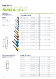
AS 12<br />
AS 18<br />
Blanking strips<br />
for the covering of spare equipment openings<br />
12 modules 18 mm each<br />
divisible every 9 mm<br />
colour grey, similar RAL 7035<br />
Blanking strips<br />
for the covering of spare equipment openings<br />
18 modules 18 mm each<br />
divisible every 9 mm<br />
colour grey, similar RAL 7035
<strong>Mi</strong> <strong>Distribution</strong> <strong>boards</strong> <br />
Accessories<br />
<strong>Mi</strong> SS 22<br />
Busbar 12 x 5 mm<br />
length 2400 mm<br />
conductor material Cu<br />
busbar rated current 250 A as N/PE<br />
busbar rated current 400 A as PE<br />
Service<br />
<strong>Mi</strong> SS 25<br />
Busbar 12 x 10 mm<br />
length 2400 mm<br />
conductor material Cu<br />
busbar rated current 250 A as L1-L3<br />
busbar rated current 400 A as N<br />
busbar rated current 630 A as PE<br />
DK<br />
<strong>Mi</strong> SS 40<br />
Busbar 20 x 10 mm<br />
length 2400 mm<br />
conductor material Cu<br />
busbar rated current 400 A as L1-L3<br />
KV<br />
<strong>Mi</strong> SS 45<br />
Busbar 25 x 10 mm<br />
length 2400 mm<br />
conductor material Cu<br />
busbar rated current 630 A as N<br />
<strong>Mi</strong> SS 63<br />
Busbar 30 x 10 mm<br />
length 2400 mm<br />
conductor material Cu<br />
busbar rated current 630 A as L1-L3<br />
<strong>Mi</strong><br />
<strong>Mi</strong> ST 25<br />
Busbar support 250 A<br />
busbar rated current 250 A<br />
for assembly in <strong>Mi</strong>-Empty boxes<br />
centreline spacing of busbars 60 mm<br />
for busbars 12 x 10 mm (L1 - L3)<br />
for busbars 12 x 5 mm (N+PE)<br />
with fixing screws<br />
<br />
<br />
<br />
<br />
<br />
<br />
<br />
<br />
<br />
<br />
MC<br />
<br />
<br />
<strong>Mi</strong> ST 41<br />
Busbar support 400 A<br />
busbar rated current 400 A<br />
for assembly in <strong>Mi</strong>-Empty boxes<br />
centreline spacing of busbars 60 mm<br />
for busbars 20 x 10 mm (L1 - L3)<br />
for busbars 12 x 5 mm (PE)<br />
for busbars 12 x 10 mm (N)<br />
<br />
<br />
<br />
<br />
<br />
<br />
<br />
<br />
<br />
<br />
<br />
<br />
HENPAS<br />
LES<br />
<strong>Mi</strong> ST 63<br />
Busbar support 630 A<br />
busbar rated current 630 A<br />
for assembly in <strong>Mi</strong>-Empty boxes<br />
centreline spacing of busbars 60 mm<br />
for busbars 30 x 10 mm (L1 - L3)<br />
for busbars 12 x 10 mm (PE)<br />
for busbars 25 x 10 mm (N)<br />
<br />
<br />
<br />
<br />
<br />
<br />
<br />
<br />
<br />
<br />
157<br />
Technics<br />
References/Types
<strong>Mi</strong> <strong>Distribution</strong> <strong>boards</strong> <br />
Accessories<br />
MC<br />
<strong>Mi</strong><br />
KV<br />
DK<br />
Service<br />
<strong>Mi</strong> VS 100 Wiring strip 100 A<br />
for connections of 100 A between busbars<br />
and built-in equipment<br />
wiring instructions for equipment (e.g. wire<br />
range ...mm²) must be observed<br />
cross-section 3 x 9 x 0,8 mm<br />
<strong>Mi</strong> VS 160 Wiring strip 160 A<br />
for connections of 160 A between busbars<br />
and built-in equipment<br />
wiring instructions for equipment (e.g. wire<br />
range ...mm²) must be observed<br />
cross-section 6 x 9 x 0,8 mm<br />
<strong>Mi</strong> VS 250 Wiring strip 250 A<br />
for connections of 250 A between busbars<br />
and built-in equipment<br />
wiring instructions for equipment (e.g. wire<br />
range ...mm²) must be observed<br />
cross-section 6 x 15,5 x 0,8 mm<br />
<strong>Mi</strong> VS 400 Wiring strip 400 A<br />
for connections of 400 A between busbars<br />
and built-in equipment<br />
wiring instructions for equipment (e.g. wire<br />
range ...mm²) must be observed<br />
cross-section 10 x 15,5 x 0,8 mm<br />
<strong>Mi</strong> VS 630 Wiring strip 630 A<br />
for connections of 630 A between busbars<br />
and built-in equipment<br />
wiring instructions for equipment (e.g. wire<br />
range ...mm²) must be observed<br />
cross-section 11 x 20 x 1 mm<br />
LES<br />
HENPAS<br />
Technics<br />
VA 400<br />
VA 630<br />
DA 240<br />
Wiring terminal up to 400 A<br />
terminal for direct connection of laminated copper wiring strip<br />
(<strong>Mi</strong> VS 250 and <strong>Mi</strong> VS 400) up to 400 A<br />
onto switchgear with flat contact M10<br />
tightening torque 8 Nm<br />
Wiring terminal up to 630 A<br />
terminal for direct connection of laminated copper wiring strip<br />
(<strong>Mi</strong> VS 630) up to 630 A<br />
onto switchgear with flat contact M12<br />
tightening torque 22-24 Nm<br />
Terminal for direct connection<br />
up to 400 A<br />
for mounting onto switchgear with flat contact M10<br />
with insulating cover<br />
rated connecting capacity<br />
35-70 mm² s (round), Cu/Alu<br />
50-185 mm² s (sector), Cu/Alu<br />
35-50 mm² sol, Cu/Alu<br />
70-240 mm² sol (sector), Cu/Alu<br />
tightening torque 22 Nm<br />
Prior to connection, aluminium conductors must be prepared according to the relevant<br />
technical recommendations.<br />
References/Types<br />
158
<strong>Mi</strong> <strong>Distribution</strong> <strong>boards</strong> <br />
Accessories<br />
for copper and aluminium conductors<br />
for insertion in <strong>Mi</strong>-Empty boxes of sizes 2 to 8<br />
Prior to connection, aluminium conductors must<br />
be prepared according to the relevant technical<br />
recommendations.<br />
complete on mounting plate<br />
with fixing screws<br />
for terminal technology refer to technical data<br />
Service<br />
<strong>Mi</strong> VE 120 Terminal for incoming/outgoing cables<br />
current carrying capacity 250 A<br />
4-pole<br />
clamping units per pole: 2 x 16-150 mm², 4 x 16-70 mm²<br />
outgoing wiring strip <strong>Mi</strong> VS ..<br />
tightening torque 20 Nm<br />
DK<br />
<strong>Mi</strong> VE 125 Terminal for incoming/outgoing cables<br />
current carrying capacity 250 A<br />
5-pole<br />
incoming or outgoing per pole: 2 x 16-150 mm², 4 x 16-70 mm²<br />
outgoing wiring strip <strong>Mi</strong> VS ..<br />
tightening torque 20 Nm<br />
KV<br />
<strong>Mi</strong> VE 240 Terminal for incoming/outgoing cables<br />
current carrying capacity 400 A<br />
4-pole<br />
incoming or outgoing cables per pole: 2 x 50-240 mm², 4 x 25-120 mm²<br />
outgoing wiring strip <strong>Mi</strong> VS ..<br />
tightening torque 40 Nm<br />
<strong>Mi</strong><br />
<strong>Mi</strong> VE 245 Terminal for incoming/outgoing cables<br />
current carrying capacity 400 A<br />
5-pole<br />
incoming or outgoing cables per pole: 2 x 50-240 mm², 4 x 25-120 mm²<br />
outgoing wiring strip <strong>Mi</strong> VS ..<br />
tightening torque 40 Nm<br />
MC<br />
<strong>Mi</strong> VE 302 Terminal for incoming/outgoing cables<br />
current carrying capacity 630 A<br />
2-pole<br />
incoming or outgoing cables per pole: 2 x 120-300 mm², 4 x 95-185 mm²<br />
outgoing wiring strip <strong>Mi</strong> VS ..<br />
tightening torque 50 Nm<br />
LES<br />
<strong>Mi</strong> VE 303 Terminal for incoming/outgoing cables<br />
current carrying capacity 630 A<br />
3-pole<br />
incoming or outgoing cables per pole: 2 x 120-300 mm², 2 x 95-185 mm²<br />
outgoing wiring strip <strong>Mi</strong> VS ..<br />
tightening torque 50 Nm<br />
<strong>Mi</strong> VE 304 terminal for incoming/outgoing cables<br />
current carrying capacity 630 A<br />
4-pole<br />
incoming or outgoing cables per pole: 2 x 120-300 mm², 4 x 95-185 mm²<br />
outgoing wiring strip <strong>Mi</strong> VS 630<br />
tightening torque 50 Nm<br />
HENPAS<br />
Technics<br />
159<br />
References/Types
DK<br />
KV<br />
<strong>Mi</strong><br />
LES<br />
HENPAS<br />
Technics<br />
<strong>Mi</strong> <strong>Distribution</strong> <strong>boards</strong> <br />
Accessories<br />
Service<br />
<strong>Mi</strong> NK 1<br />
N terminal<br />
conductor material Cu<br />
rated connecting capacity 2 x 35 mm²<br />
<strong>Mi</strong> NK 2<br />
N terminal<br />
conductor material Cu<br />
rated connecting capacity 2 x 70 mm²<br />
<strong>Mi</strong> NK 3<br />
N terminal<br />
conductor material Cu<br />
rated connecting capacity 4 x 35 mm²<br />
<strong>Mi</strong> NK 4<br />
N terminal<br />
conductor material Cu<br />
screws 2 x M 10<br />
MC<br />
KKL 25<br />
PE or N connecting terminal<br />
as a connecting terminal or wiring pin<br />
for installation on DIN rails in accordance with IEC 60 715,<br />
top hat profile 35 mm<br />
with two connected clamping units for solid, stranded or flexible copper<br />
conductors, with gas-tight crimped end sleeve<br />
current carrying capacity 102 A<br />
width 29 mm<br />
conductor cross section 1 x 35 mm², 2 x 25 mm²,<br />
2 x 16 mm², 3 x 10 mm², 3 x 6 mm²<br />
References/Types<br />
160
<strong>Mi</strong> <strong>Distribution</strong> <strong>boards</strong> <br />
Accessories<br />
KKL 34<br />
Main line branch terminal<br />
3-pole as connecting terminal 25 mm²<br />
per 4 x 1.5-25 mm² as L1-L3<br />
for installation on DIN rail <strong>Mi</strong> TS ..<br />
in accordance with EN 50 022, 35 mm DIN rail<br />
width 61 mm<br />
<br />
<br />
<br />
Service<br />
KKL 48<br />
Main line branch terminal<br />
4-pole as connecting terminal 25 mm²<br />
per 4 x 1.5-25 mm² as L1-L3, 8 x 1.5-25 mm² as N<br />
for installation on DIN rail <strong>Mi</strong> TS ..<br />
in accordance with EN 50 022, 35 mm DIN rail<br />
width 81 mm<br />
<br />
<br />
<br />
DK<br />
KKL 54<br />
Main line branch terminal<br />
5-pole as connecting terminal 25 mm²<br />
per 4 x 1.5-25 mm² as L1-L3, 8 x 1.5-25 mm² as N, 4 x<br />
1.5-25 mm² as PE<br />
for installation on DIN rail <strong>Mi</strong> TS ..<br />
in accordance with EN 50 022, 35 mm DIN rail<br />
width 100 mm<br />
<br />
<br />
KV<br />
Technics<br />
HENPAS<br />
LES<br />
MC<br />
<strong>Mi</strong><br />
<br />
161<br />
References/Types
<strong>Mi</strong><br />
<strong>Mi</strong> <strong>Distribution</strong> <strong>boards</strong> <br />
Accessories<br />
Service<br />
Terminals for<br />
direct busbar connection<br />
For solid (sol), stranded (s), flexible (f) copper conductors<br />
with gas-tight crimped end sleeve and for<br />
laminated wiring strip<br />
Remarks:<br />
For observance of insulation resistance<br />
clearances of 10 mm are necessary between<br />
different potentials and of 15 mm between<br />
conductive metal parts.<br />
DK<br />
Type<br />
for busbars<br />
conductor cross<br />
section<br />
wiring strip<br />
tightening<br />
torque<br />
KS 16 F ... x 5 mm 1,5-16 mm 2 Cu 4 Nm<br />
KV<br />
KS 16 Z ... x 10 mm 1,5-16 mm 2 Cu 4 Nm<br />
100 A: <strong>Mi</strong> VS 100<br />
KS 35 F ... x 5 mm 4-35 mm 2 Cu 160 A: <strong>Mi</strong> VS 160 6 Nm<br />
100 A: <strong>Mi</strong> VS 100<br />
KS 35 Z ... x 10 mm 4-35 mm 2 Cu 160 A: <strong>Mi</strong> VS 160 6 Nm<br />
MC<br />
250 A: <strong>Mi</strong> VS 250<br />
KS 120 F ... x 5 mm 25-120 mm 2 Cu 400 A: <strong>Mi</strong> VS 400 20 Nm<br />
250 A: <strong>Mi</strong> VS 250<br />
KS 120 Z ... x 10 mm 25-120 mm 2 Cu 400 A: <strong>Mi</strong> VS 400 20 Nm<br />
LES<br />
Aluminium conductors must be prepared prior<br />
to connection in accordance with the relevant<br />
12x5 mm/<br />
KS 240/12 12x10 mm<br />
technical recommendations.<br />
35-240 mm 2 Cu/Alu 40 Nm<br />
HENPAS<br />
KS 240/20 20x10 mm 120-240 mm 2 Cu 30 Nm<br />
KS 150 12x10 mm 35-150 mm 2 Cu 630 A: <strong>Mi</strong> VS 630 20 Nm<br />
Technics<br />
25x10 mm/<br />
KS 240 30x10 mm 150-240 mm 2 Cu 30 Nm<br />
References/Types<br />
162<br />
25x10 mm/<br />
KS 240 V 30x10 mm 630 A: <strong>Mi</strong> VS 630 30 Nm
<strong>Mi</strong> <strong>Distribution</strong> <strong>boards</strong> <br />
Accessories<br />
<strong>Mi</strong> busbar boxes<br />
Service<br />
busbar rated current<br />
250 A 400 A 630 A<br />
<br />
DK<br />
<br />
<br />
<br />
<br />
<br />
<br />
<br />
<br />
<br />
<br />
<br />
<br />
<br />
<br />
KV<br />
<br />
<br />
<br />
<br />
<br />
<br />
<br />
<br />
<br />
<br />
<br />
<br />
<br />
<br />
<br />
<strong>Mi</strong><br />
<br />
<br />
<br />
MC<br />
<br />
<br />
<br />
<br />
<br />
<br />
<br />
<br />
<br />
<br />
<br />
<br />
<br />
<br />
<br />
<br />
<br />
<br />
<br />
<br />
LES<br />
<br />
<br />
<br />
<br />
<br />
<br />
<br />
<br />
<br />
<br />
HENPAS<br />
<br />
<br />
<br />
<br />
Technics<br />
<br />
<br />
<br />
<br />
163<br />
References/Types
<strong>Mi</strong><br />
<strong>Mi</strong> <strong>Distribution</strong> <strong>boards</strong> <br />
Accessories<br />
Service<br />
DK<br />
KV<br />
<strong>Mi</strong> WD 2<br />
<strong>Mi</strong> SV 25<br />
<strong>Mi</strong> SV 45<br />
Wall gasket<br />
for the assembly of <strong>Mi</strong> boxes<br />
box walls 150 or 300 mm<br />
consisting of 1 seal, 4 wedge links, 1 bracket<br />
Busbar connector<br />
5-pole<br />
busbar rated current 250 A<br />
with wall gasket<br />
for the assembly of <strong>Mi</strong> boxes containing busbars<br />
tightening torque 6 Nm<br />
Note: Busbars 250 A and 400 A can only be connected with busbar connector <strong>Mi</strong> SV 25.<br />
Connecting of busbars with different rated current only under care and attention of the<br />
corresponding short circuit and overload standards.<br />
Busbar connector<br />
5-pole<br />
busbar rated current 400 A and 630 A<br />
with wall gasket<br />
for the assembly of <strong>Mi</strong> boxes containing busbars<br />
tightening torque 10 Nm<br />
<strong>Mi</strong> WT 1<br />
Wall separator<br />
for subdivision of 300 mm box walls into 2 x 150 mm for flange or box mounting<br />
MC<br />
<strong>Mi</strong> BE<br />
Fixing spares<br />
for the assembly of <strong>Mi</strong> boxes<br />
when converting existing installations<br />
consisting of 4 wedge links and 5 wedges<br />
LES<br />
HENPAS<br />
<strong>Mi</strong> FM 15 Flange <br />
<br />
with fixing wedges and seal<br />
box wall 150 mm<br />
knockouts 3 x M 20, 1 x M 32/40/50<br />
<strong>Mi</strong> FP 20<br />
Flange<br />
with fixing wedges and seal<br />
useable area<br />
box wall 300 mm<br />
without cable entry<br />
<strong>Mi</strong> FM 20 Flange <br />
<br />
with fixing wedges and seal<br />
box wall 300 mm<br />
knockouts 15 x M 16, 15 x M 20<br />
<br />
usable mounting area<br />
<br />
<br />
<br />
Technics<br />
<strong>Mi</strong> FM 25 Flange <br />
<br />
with fixing wedges and seal<br />
box wall 300 mm<br />
knockouts 19 x M 16/25<br />
References/Types<br />
164
<strong>Mi</strong> <strong>Distribution</strong> <strong>boards</strong> <br />
Accessories<br />
<strong>Mi</strong> FM 32 Flange <br />
<br />
with fixing wedges and seal<br />
box wall 300 mm<br />
knockouts 8 x M 25/32, 1 x M 25/32/40<br />
Service<br />
<strong>Mi</strong> FM 40 Flange <br />
<br />
with fixing wedges and seal<br />
box wall 300 mm<br />
knockouts<br />
2 x M 25/32, 5 x M 32/40<br />
DK<br />
<strong>Mi</strong> FM 50 Flange <br />
<br />
with fixing wedges and seal<br />
box wall 300 mm<br />
knockouts 2 x M 20, 4 x M 32/40/50<br />
<strong>Mi</strong> FM 60 Flange <br />
<br />
with fixing wedges and seal<br />
box wall 300 mm<br />
knockouts 3 x M 40/50/63<br />
KV<br />
<strong>Mi</strong> FP 38 Flange <br />
with elastic membranes for cable entry<br />
with fixing wedges and seal<br />
box wall 300 mm<br />
sealing range<br />
29 x Ø 7-12 mm<br />
4 x Ø 7-14 mm<br />
4 x Ø 11-20 mm<br />
1 x Ø 16-29 mm<br />
<strong>Mi</strong> FP 70 Flange <br />
<strong>Mi</strong> FP 72 Flange <br />
<strong>Mi</strong> FM 63<br />
for cables<br />
max. 72 mm external diameter<br />
sealing range<br />
30-72 mm<br />
with fixing wedges and seal<br />
box wall 300 mm<br />
for 2 cables<br />
max. 72 mm external diameter<br />
sealing range<br />
2 x each 30-72 mm<br />
with fixing wedges and seal<br />
box wall 300 mm<br />
Flange<br />
with extended cable arrangement space<br />
with fixing wedges and seal<br />
box wall 300 mm<br />
knockouts 3x M 40/50/63<br />
<strong>Mi</strong> FP 82 Cable insert <br />
for 2 cables<br />
max. 74 mm external diameter<br />
degree of protection IP 54 only with<br />
additional strain and pressure relief<br />
(e.g. <strong>Mi</strong> ZE 62)<br />
box wall 300 mm<br />
sealing range 2 x 30-72 mm<br />
<br />
<br />
<br />
<br />
<br />
<br />
<br />
<br />
165<br />
References/Types Technics HENPAS<br />
LES<br />
MC<br />
<strong>Mi</strong>
KV<br />
<strong>Mi</strong><br />
HENPAS<br />
Technics<br />
<strong>Mi</strong> <strong>Distribution</strong> <strong>boards</strong> <br />
Accessories<br />
Service<br />
DK<br />
<strong>Mi</strong> ZE 62<br />
<strong>Mi</strong> GS 30<br />
<strong>Mi</strong> BF 20<br />
Cable strain relief<br />
for 2 cables with max. 60 mm external diameter<br />
with fixing rail 284 mm long<br />
to be used only in connection with cable insertion <strong>Mi</strong> FP 82<br />
Box fin<br />
removable<br />
for inserting cables across 2 boxes<br />
for box walls 300 mm<br />
can be retrofitted<br />
Ventilation flange<br />
for ventilation of <strong>Mi</strong>-<strong>Distribution</strong> <strong>boards</strong> in the event of extremely high internal temperatures<br />
or a risk of water condensation<br />
for vertical installation on the lateral box walls<br />
degree of protection IP 23<br />
<strong>Mi</strong> PL 2<br />
Sealing caps<br />
2 sealing caps for converting the lid fasteners<br />
<strong>Mi</strong> SR 4<br />
Conversion set<br />
4 fastening covers<br />
for converting lid fasteners for manual operation to tool operation<br />
MC<br />
<strong>Mi</strong> SN 4<br />
Conversion set<br />
4 manual actuators<br />
for converting lid fasteners from tool operation to manual operation<br />
LES<br />
<strong>Mi</strong> DV 01<br />
Locking device insertion<br />
only in connection with <strong>Mi</strong> PL 2, <strong>Mi</strong> SR 4 or <strong>Mi</strong> SN 4<br />
References/Types<br />
166
<strong>Mi</strong> <strong>Distribution</strong> <strong>boards</strong> <br />
Accessories<br />
<strong>Mi</strong> ZS 01<br />
<strong>Mi</strong> ZS 02<br />
<strong>Mi</strong> ZS 03<br />
Lid lock<br />
locking device I<br />
2 cylinder locks<br />
2 keys<br />
only in connection with <strong>Mi</strong> ZS 03<br />
Is used instead of fasteners for hand or tool operation in order to prevent unauthorized<br />
opening of lids.<br />
Lid lock<br />
locking device II<br />
2 cylinder locks<br />
2 keys<br />
only in connection with <strong>Mi</strong> ZS 03<br />
Is used instead of fasteners for hand or tool operation in order to prevent unauthorized<br />
opening of lids.<br />
Locking device insertion<br />
for lid lock <strong>Mi</strong> ZS 01 or <strong>Mi</strong> ZS 02<br />
Service<br />
DK<br />
KV<br />
<strong>Mi</strong> ZS 20<br />
<strong>Mi</strong> hinged lid<br />
Usable in <strong>Mi</strong> boxes:<br />
for <strong>Mi</strong> box sizes 1, 2, 3 and 4.<br />
When assembling several boxes, the insertion can only<br />
be carried out for the external boxes.<br />
For operating installation device within a large area.<br />
The lid keeps permanently connected to the box.<br />
Backstop of lids: Position of box: vertical Position of box: horizontal<br />
left right top bottom left right top bottom<br />
size 1: • • • • • • • •<br />
size 2: • • • • • • • •<br />
size 3: • • • - - - • •<br />
size 4: • • • - - - • •<br />
<strong>Mi</strong><br />
MC<br />
<strong>Mi</strong> ZS 40<br />
<strong>Mi</strong> heavy-duty hinge joints<br />
for single and assembled <strong>Mi</strong> boxes, sizes 1, 2, 3, 4 and 8.<br />
Hinge joints are to be mounted on the inside of the boxes.<br />
For a good functionality, enough space has to be available.<br />
LES<br />
Technics<br />
HENPAS<br />
167<br />
References/Types
HENPAS<br />
Technics<br />
<strong>Mi</strong> <strong>Distribution</strong> <strong>boards</strong> <br />
Accessories<br />
Service<br />
<strong>Mi</strong> KL 6<br />
Hinged flap<br />
modules 1 x 6 x 18 mm<br />
with drill and saw template<br />
opening dimensions 117 x 60 mm<br />
sealable<br />
wall thickness 1.5-4.5 mm<br />
<br />
<br />
<br />
<br />
<br />
DK<br />
<strong>Mi</strong> BS 6 Protection cover <br />
for <strong>Mi</strong> KL 6<br />
with fixing screws<br />
modules 1 x 6 x 18 mm<br />
<br />
<br />
<br />
KV<br />
<strong>Mi</strong> KL 12<br />
Hinged flap<br />
modules 1 x 12 x 18 mm<br />
with drill and saw template<br />
opening dimensions 220 x 60 mm<br />
sealable<br />
wall thickness 1.5-4.5 mm<br />
<br />
<br />
<br />
<br />
<br />
<br />
<br />
<strong>Mi</strong> BS 12 Protection cover <br />
for <strong>Mi</strong> KL 12<br />
with fixing screws<br />
modules 1 x 12 x 18 mm<br />
<br />
<br />
<br />
<strong>Mi</strong><br />
MC<br />
<strong>Mi</strong> SK 01<br />
NZ KL 54<br />
Hinged flap lock<br />
for retrofitting in box lids of <strong>Mi</strong> circuit-breaker boxes<br />
for protecting the switchgear located behind the hinged flap against unauthorised access<br />
(only effective in connection with lid lock <strong>Mi</strong> ZS ..)<br />
KWH meter window flap<br />
opening dimensions 140 x 310 mm<br />
for tool or manual operation<br />
sealable<br />
can be locked with padlock (clip diameter max. 6 mm)<br />
complete with screws<br />
degree of protection IP 54<br />
LES<br />
<strong>Mi</strong> SA 2<br />
Dust cover<br />
for 2 lid fittings<br />
set consisting of 4 parts<br />
References/Types<br />
168
<strong>Mi</strong> <strong>Distribution</strong> <strong>boards</strong> <br />
Accessories<br />
<strong>Mi</strong> AL 4<br />
<strong>Mi</strong> MS 2<br />
MX 0101<br />
MX 0112<br />
External brackets<br />
for external box fixing<br />
set consisting of 4 fixing brackets, 4 screws<br />
Mounting profile<br />
for wall-mounted assembly of <strong>Mi</strong>-distribution <strong>boards</strong> up to 900x1200 mm<br />
with 8 screws M6 x 16 for box fixing<br />
sendzimir galvanised steel profile with structured powder coating<br />
colour RAL 7032 slate grey<br />
length 1950 mm<br />
Mounting profile set<br />
U-profile for constructing a mounting frame<br />
consisting of:<br />
1 x mounting rail, length 1950 mm<br />
2 x fixing brackets<br />
1 x flat connector with connecting screws<br />
steel profile galvanised with a structured powder coating<br />
colour RAL 7016 anthracite grey<br />
Fixing elements for T or L connections<br />
for constructing a mounting frame<br />
consisting of: 2 couplers with screws and nuts<br />
sheet steel<br />
colour RAL 7016 anthracite grey<br />
<strong>Mi</strong><br />
KV<br />
DK<br />
Service<br />
MX 0105<br />
Coupler set<br />
consisting of:<br />
2 x couplers with connecting screws<br />
steel profile galvanised with a structured powder coating<br />
colour RAL 7016 anthracite grey<br />
MC<br />
MX 0110<br />
Lifting eyes set<br />
consisting of:<br />
2 x lifting eyes with connecting screws<br />
chromated<br />
LES<br />
MX 0111 M 6 x 16<br />
self-tapping for fixing the <strong>Mi</strong> box<br />
onto mounting profile MX 0101<br />
set with 12 pieces<br />
HENPAS<br />
Technics<br />
169<br />
References/Types
Technics<br />
<strong>Mi</strong> <strong>Distribution</strong> <strong>boards</strong> <br />
Accessories<br />
HENPAS<br />
LES<br />
MC<br />
<strong>Mi</strong><br />
KV<br />
DK<br />
Service<br />
<strong>Mi</strong> DA 72<br />
<strong>Mi</strong> HS 20<br />
MK 0107<br />
MK 0106<br />
MK 0105<br />
MK 0108<br />
MK 0109<br />
Terminal set for direct connection<br />
terminal for copper and aluminium conductors<br />
for the connection of switch disconnector 630 A (<strong>Mi</strong> 7865)<br />
1 x 120-300 mm² s (round)<br />
1 x 120-300 mm² s (sector)<br />
1 x 120-185 mm² sol (sector)<br />
2 x 70-150 mm² s (round)<br />
2 x 95-150 mm² s (sector)<br />
2 x 70 mm² sol (round)<br />
2 x 95-150 mm² sol (sector)<br />
Auxiliary contact<br />
2-pole<br />
rated current 6 A<br />
2 changeover contacts for retrofitting on switch disconnectors 160-630 A<br />
connection with flat connector 6.3 mm<br />
Auxiliary changeover contact<br />
1-pole<br />
rated current 6 A<br />
for circuit-breakers 16-630 A<br />
The auxiliary switches can report different functions<br />
depending on their mounting location in the circuit-breaker.<br />
circuit-breaker 160/250 A = 2x ON/OFF signal + 1x tripping signal + 1x electric error signal<br />
circuit-breaker 400/630 A = 3x ON/OFF signal + 1x tripping signal + 1x electric error signal<br />
Open-circuit shunt release<br />
for circuit-breakers 16-630 A<br />
AC 50/60 Hz, 200 to 240 V<br />
the main contacts of the circuit-breaker are opened<br />
when voltage of more than 0.7 x Un is applied<br />
Undervoltage release<br />
for circuit-breakers 16-630 A<br />
AC 50/60 Hz, 200 to 240 V<br />
when the control voltage drops below 0.35 - 0.7 x Un,<br />
the main contacts of the circuit-breaker are opened<br />
the closing of the contacts can only take place with voltages above 0.85 x Un<br />
Circuit-breaker terminal for direct connection<br />
for circuit-breakers 400 A and 630 A<br />
set with 3 pieces<br />
clamping range 1 x 35-300 mm²<br />
Circuit-breaker terminal for direct connection<br />
for circuit-breakers 400 A and 630 A<br />
set with 3 pieces<br />
clamping range 2 x 70-240 mm²<br />
References/Types<br />
170
<strong>Mi</strong> <strong>Distribution</strong> <strong>boards</strong> <br />
Accessories<br />
Z RK 19<br />
Cable entry cover<br />
height 150 mm x depth 190 mm<br />
length 2000 mm<br />
material plastics<br />
colour RAL 7030<br />
<br />
<br />
Service<br />
Z RKW 19 Support for cable entry cover<br />
height 150 mm x depth 190 mm<br />
material plastics<br />
Technics<br />
HENPAS<br />
LES<br />
MC<br />
<strong>Mi</strong><br />
KV<br />
DK<br />
Z RKZ 19<br />
End caps for cable entry cover<br />
height 150 mm x depth 190 mm<br />
material plastics<br />
colour RAL 7030<br />
171<br />
References/Types
Service<br />
DK<br />
KV<br />
<strong>Mi</strong><br />
Technics<br />
<strong>Mi</strong> <strong>Distribution</strong> <strong>boards</strong> <br />
Technical details<br />
MC<br />
LES<br />
HENPAS<br />
Operating and ambient conditions 173<br />
Characteristics of the material 173<br />
Rated power dissipation of empty boxes 174<br />
Rated current and short circuit resistance of busbars 174<br />
Standards and requirements 174<br />
Dimensions in mm 175<br />
Terminal technology 176<br />
Installation of equipment 177<br />
Busbars 177<br />
Terminals for incoming cables 177<br />
Wall mounting 178<br />
Hinged lid, heavy-duty hinge joints 178<br />
Mounting instructions for hinge joints and frames 179<br />
Mounting frame 180<br />
Assembly of <strong>Mi</strong> <strong>Distribution</strong> <strong>boards</strong> 181 - 184<br />
References/Types<br />
172
<strong>Mi</strong> <strong>Distribution</strong> <strong>boards</strong> <br />
Technical details<br />
Operating and ambient conditions, characteristics of the material<br />
Application area<br />
Ambient temperature<br />
- Average value<br />
over 24 hours<br />
- Maximum value<br />
- <strong>Mi</strong>nimum value<br />
<strong>Mi</strong> distribution <strong>boards</strong><br />
Operating and ambient conditions<br />
Suitable for installation indoors and<br />
installation outdoors, protected against weather influences<br />
Resistant to occasional cleaning procedures (direct jet)<br />
max. with high-pressure cleaner without additives<br />
water pressure: max. 65 bar, water temperature: max. 50° C, distance ≥ 0.5 m<br />
box and cable entries at least IP 65<br />
+ 35° C<br />
+ 40° C<br />
− 5° C<br />
Service<br />
DK<br />
Relative<br />
humidity<br />
- short-time<br />
Material<br />
Temperature<br />
resistance<br />
Burning behaviour<br />
- Glow wire test<br />
IEC 60 695-2-1<br />
- UL Subject 94<br />
50% at 40° C<br />
100% at 25° C<br />
Characteristics of the material<br />
PC-Polycarbonate<br />
thermoplastics<br />
− 40° C to<br />
+ 90° C<br />
750° C<br />
V-2<br />
flame-retardant<br />
self-extinguishing<br />
Toxic behaviour halogen-free 3)<br />
Chemical<br />
resistance 2)<br />
- Acid 10 %<br />
- Lye 10 %<br />
- Alcohol<br />
- Petrol (MAK) 1)<br />
- Benzene (MAK) 1)<br />
- <strong>Mi</strong>neral oil<br />
silicone-free<br />
(+ = resistance 0 = partially resistance − = not resistant)<br />
+<br />
+<br />
0<br />
+<br />
−<br />
+<br />
1) (MAK) - Maximum allowable concentration (work place)<br />
2) The specifications on chemical resistance are a general guide. In individual cases it may be necessary to check resistance in combination with other chemicals<br />
and ambient conditions (termperature, concentration, etc.)<br />
3) „Halogen-free“ in accordance with IEC 754-2 „Common test methods for cables - Determination of the amount of halogen acid gas“.<br />
LES<br />
MC<br />
<strong>Mi</strong><br />
KV<br />
Technics<br />
HENPAS<br />
173<br />
References/Types
<strong>Mi</strong> <strong>Distribution</strong> <strong>boards</strong> <br />
Technical details<br />
References/Types Technics HENPAS<br />
LES<br />
MC<br />
<strong>Mi</strong><br />
KV<br />
DK<br />
Service<br />
Rated power dissipation of empty boxes<br />
The following table indicates the maximum rated power dissipation<br />
for any empty boxes. A difference is made between single<br />
boxes with lateral, frontal and rear radiation, an equipment with<br />
frontal and rear radiation.<br />
Box type<br />
174<br />
External<br />
dimensions<br />
W x H x D<br />
in mm<br />
Power dissipation (W/box)<br />
single box<br />
<strong>Mi</strong> 0100 300x150x170 25 18<br />
<strong>Mi</strong> 0101 300x150x170 25 18<br />
<strong>Mi</strong> 0200 300x300x170 40 32<br />
<strong>Mi</strong> 0201 300x300x170 40 32<br />
<strong>Mi</strong> 0210 300x300x214 46 38<br />
<strong>Mi</strong> 0211 300x300x214 46 38<br />
<strong>Mi</strong> 0220 300x300x182 40 32<br />
<strong>Mi</strong> 0221 300x300x182 40 32<br />
<strong>Mi</strong> 0300 300x450x170 53 45<br />
<strong>Mi</strong> 0301 300x450x170 53 45<br />
<strong>Mi</strong> 0310 300x450x214 65 53<br />
<strong>Mi</strong> 0311 300x450x214 65 53<br />
<strong>Mi</strong> 0400 300x600x170 70 58<br />
<strong>Mi</strong> 0401 300x600x170 70 58<br />
<strong>Mi</strong> 0410 300x600x214 82 60<br />
<strong>Mi</strong> 0411 300x600x214 82 60<br />
<strong>Mi</strong> 0400 +<br />
<strong>Mi</strong> ZR 4<br />
<strong>Mi</strong> 0401 +<br />
<strong>Mi</strong> ZR 4<br />
300x600x255 85 60<br />
300x600x255 85 60<br />
<strong>Mi</strong> 0800 600x600x170 120 98<br />
<strong>Mi</strong> 0801 600x600x170 120 98<br />
<strong>Mi</strong> 0800 +<br />
<strong>Mi</strong> ZR 8<br />
<strong>Mi</strong> 0801 +<br />
<strong>Mi</strong> ZR 8<br />
600x600x255 142 120<br />
600x600x255 142 120<br />
in assemblies<br />
The values indicated refer to the ambient temperature of 25° C<br />
and an interior temperature of 55° C.<br />
For the nominal load factor the square dependence of the power<br />
dissipation from the current shall be taken into consideration.<br />
Rated current and short circuit resistance<br />
of busbars<br />
Rated<br />
current<br />
A<br />
busbar<br />
crosssection<br />
mm<br />
Material<br />
Rated peak<br />
withstand<br />
current<br />
I pk<br />
kA cos ϕ<br />
250 12x10 Cu 30 0,3 300<br />
400 20x10 Cu 30 0,3 300<br />
630 30x10 Cu 45 0,3 300<br />
distances<br />
between<br />
busbar<br />
supports<br />
max. mm<br />
<strong>Mi</strong>-distribution <strong>boards</strong> comply with the requirements for<br />
type-tested switchgear and controlgear assemblies (TTA)<br />
in accordance with IEC 60 439-1/EN 60 439-1.<br />
Type-tested switchgear assemblies are switchgear and controlgear<br />
assemblies which are assembled and wired according to<br />
manufacturer data without essential deviations from the original<br />
type or system.<br />
To meet these requirements for Hensel <strong>Mi</strong> <strong>Distribution</strong> <strong>boards</strong>,<br />
the following must be noted:<br />
1. The switchgear must consist of the type-tested enclosures<br />
documented in this list.<br />
2. The wiring of the equipment must be carried out with the<br />
cross-sections and conductor types indicated in Table<br />
„Rating of insulated conductors in switchgear assemblies“,<br />
Index Technics, page 212.<br />
3. Once the switchgear is completed, a routine test must be<br />
carried out in accordance with this standard.<br />
4. The test must be certified with a test report.<br />
5. The switchgear must be provided with a manufacturer’s<br />
identification mark.<br />
Compliance with important data such as<br />
- limit of temperature rise<br />
- dielectric strength<br />
- short-circuit withstand capacity<br />
- short-circuit withstand capacity of the PE conductor<br />
- IP degrees of protection<br />
- creepage distances and clearances<br />
is verified by type tests for this system.<br />
<strong>Mi</strong>-distribution <strong>boards</strong> comply with the following standards<br />
and requirements:<br />
- IEC 60 439-1 / EN 60 439-1<br />
Low voltage swichgear and control gear assemblies<br />
- IEC 999 and EN 60 999<br />
Safety requirements for screw-type and screwless-type<br />
clamping units for electrical copper conductors<br />
- EN 50 262<br />
Metric threaded cable glands for electrical installations<br />
- IEC 269<br />
Low voltage fuses<br />
- DIN 43 880<br />
Built-in equipment for electrical installations;<br />
overall dimensions and related mounting dimensions<br />
- IEC 60 529<br />
Degrees of protection provided by enclosures (IP-Code)<br />
Approvals:<br />
EZU Czech Republic<br />
MEEI Hungary
<strong>Mi</strong> <strong>Distribution</strong> <strong>boards</strong> <br />
Subline Technical details<br />
Dimensions in mm<br />
Dimensions of the interior installation depth<br />
with installed mounting plates.<br />
<strong>Mi</strong> 0100<br />
<strong>Mi</strong> 0101<br />
<br />
<br />
<br />
<br />
<br />
<strong>Mi</strong> 0310<br />
<strong>Mi</strong> 0311<br />
<br />
<br />
<br />
<br />
<br />
Service<br />
<strong>Mi</strong><br />
<br />
<br />
<br />
<br />
<br />
<br />
<br />
<br />
<br />
<br />
DK<br />
<strong>Mi</strong> 0200<br />
<strong>Mi</strong> 0201<br />
<br />
<br />
<br />
<br />
<br />
<br />
<br />
<br />
<br />
<br />
<br />
<br />
<br />
KV<br />
MC<br />
LES<br />
HENPAS<br />
<strong>Mi</strong> 0300<br />
<strong>Mi</strong> 0301<br />
<br />
<br />
<br />
<br />
<br />
<br />
<br />
<br />
<br />
<br />
<br />
<br />
<strong>Mi</strong> 0210<br />
<strong>Mi</strong> 0211<br />
<br />
<br />
<br />
<br />
<br />
<br />
<br />
<br />
<br />
<br />
<br />
<br />
<br />
<br />
<br />
<br />
<br />
<br />
<strong>Mi</strong> 0220<br />
<strong>Mi</strong> 0221<br />
<br />
<br />
<br />
<br />
<br />
<br />
<br />
<br />
<br />
<br />
<br />
<br />
<br />
<br />
<br />
<br />
<strong>Mi</strong> 0400<br />
<strong>Mi</strong> 0401<br />
<br />
<br />
<br />
<br />
<br />
<br />
<strong>Mi</strong> 0410<br />
<strong>Mi</strong> 0411<br />
<br />
<br />
Technics<br />
<br />
<br />
<strong>Mi</strong> 0800<br />
<strong>Mi</strong> 0801<br />
<br />
<br />
<br />
<br />
<br />
<br />
<br />
<br />
<br />
<br />
<br />
<br />
<br />
<br />
<br />
<br />
<br />
<br />
<br />
<br />
<br />
<br />
175<br />
References/Types
<strong>Mi</strong> <strong>Distribution</strong> <strong>boards</strong> <br />
Technical details<br />
Terminal technology<br />
Service<br />
DK<br />
PE and N FIXCONNECT terminal<br />
Rated connecting capacity of PE and N terminals<br />
clamping unit<br />
screw-type<br />
1<br />
terminal<br />
1<br />
25 mm 2 1<br />
3<br />
4<br />
6<br />
6<br />
max.<br />
number<br />
from - to max.<br />
25 mm 2 , s, sol<br />
16 mm 2 , s, sol<br />
10 mm 2 , sol<br />
6 mm 2 , sol<br />
4 mm 2 , sol<br />
2,5 mm 2 , sol<br />
1,5 mm 2 , sol<br />
corresponding cross-sections/copper<br />
}<br />
Tested as connecting<br />
terminal for several<br />
conductors of the same<br />
cross-sections for using in<br />
one circuit<br />
max.<br />
number<br />
1<br />
1<br />
1<br />
1<br />
1<br />
1<br />
1<br />
from - to max.<br />
25 mm 2 , f<br />
16 mm 2 , f<br />
10 mm 2 , f<br />
6 mm 2 , f<br />
4 mm 2 , f<br />
2,5 mm 2 , f<br />
1,5 mm 2 , f<br />
1 1,5 - 4 mm 2 , sol plug-in<br />
1 1,5 - 4 mm 2 , f<br />
Without end ferrule; clamping<br />
4 mm 2<br />
terminal<br />
unit has to be opened with a tool<br />
when conductor is inserted.<br />
KV<br />
Current-carrying capacity: 80 A Screw-type terminals are secured against self-loosening.<br />
Terminal equipment and number of conductors to be connected<br />
number<br />
of<br />
modules<br />
mounted in<br />
<strong>Mi</strong> Circuit<br />
breaker<br />
boxes<br />
PE terminal<br />
N terminal<br />
up to 4 mm 2 up to 25 mm 2<br />
plug-in<br />
up to 4 mm 2 up to 25 mm 2 jumper<br />
<strong>Mi</strong><br />
24 (2-row) <strong>Mi</strong> 1224<br />
<strong>Mi</strong> 1220<br />
<strong>Mi</strong> 1222 12x4 mm 2 2x25 mm 2 12x4 mm 2 3x25 mm 2<br />
MC<br />
36 (3-row)<br />
48 (4-row)<br />
<strong>Mi</strong> 1336<br />
<strong>Mi</strong> 1333<br />
<strong>Mi</strong> 1448<br />
<strong>Mi</strong> 1444<br />
24x4 mm 2 6x25 mm 2 24x4 mm 2 6x25 mm 2<br />
Innovative FIXCONNECTplug-in technology for PE/N in <strong>Mi</strong> Circuit breaker boxes:<br />
LES<br />
1. Rapid connection 3. Variable and simple separation of N<br />
Plug in terminal 1.5 - 4 mm 2<br />
Plug-in jumper<br />
HENPAS<br />
Solid<br />
conductors:<br />
Simply plug-in the<br />
conductor!<br />
Screw-type terminal 1.5 - 25<br />
Flexible<br />
conductors:<br />
1. Open the clamping<br />
unit with a tool.<br />
2. Insert the<br />
conductor!<br />
Plug-in jumper<br />
Several N potentials are<br />
provided and linked by<br />
plug-in jumpers in the<br />
supplied state.<br />
N separation<br />
The N potential can be<br />
separated and reconnected<br />
via the plug-in jumper.<br />
4. Good accessibility during connection<br />
Arrangement of the PE and N terminals in<br />
<strong>Mi</strong> Circuit breaker boxes:<br />
Technics<br />
Connection of<br />
solid and stranded<br />
conductors.<br />
connection of untreated,<br />
flexible<br />
conductors (without<br />
end ferrule).<br />
2. More clamping units for practical use<br />
Terminals are<br />
fixed staggered<br />
in height<br />
More space when connecting the<br />
conductors:<br />
Removable N terminal for a simple<br />
connection of the conductors. Free<br />
accessibility of PE clamping units when<br />
inserting the conductors. The N terminal<br />
is then simply snapped in place.<br />
References/Types<br />
row(s)<br />
for modules<br />
176<br />
Terminals for PE and N<br />
until now mounted in<br />
<strong>Mi</strong> Circuit breaker boxes<br />
Hensel FIXCONNECT plug-in technology for PE/N<br />
Plug-in terminal Screw-type terminal<br />
2 (24 TE) 10 x 4 mm 2 2 x 25 mm 2 12 x 4 mm 2 3 x 25 mm 2<br />
3 (36 TE) 16 x 4 mm 2 4 x 25 mm 2 24 x 4 mm 2 6 x 25 mm 2<br />
4 (48 TE) 20 x 4 mm 2 5 x 25 mm 2 24 x 4 mm 2 6 x 25 mm 2
<strong>Mi</strong> <strong>Distribution</strong> <strong>boards</strong> <br />
Technical details<br />
Installation of equipment in protection plates:<br />
Pre-drill the sections at the corners, then saw away the section from the<br />
protection plate by using a piercing saw at middle to low cutting speed.<br />
Use coarse toothed saw blades for plastics (e.g. Bosch T 101 B).<br />
<br />
Service<br />
Equipment for busbar supports:<br />
Rated<br />
busbar current<br />
<strong>Mi</strong> ST 25 <strong>Mi</strong> ST 41 <strong>Mi</strong> ST 63<br />
250 A 400 A 630 A<br />
L1, L2, L3 12x10 mm 20x10 mm 30x10 mm<br />
N 12x5 mm 12x10 mm 25x10 mm<br />
PE 12x5 mm 12x5 mm 12x10 mm<br />
Position of busbars<br />
Note:<br />
For containing short-circuit resistance the distance between<br />
busbar suppoerts must not exceed 300 mm.<br />
<br />
<br />
250 A 400 A 630 A<br />
<br />
<br />
<br />
<br />
<br />
<br />
<br />
<br />
<br />
<br />
<br />
<br />
<br />
<br />
<br />
<br />
<br />
<br />
<br />
<br />
<br />
<br />
<br />
<br />
<br />
<br />
<br />
<br />
<br />
<br />
<br />
<br />
DK<br />
KV<br />
Busbar connector<br />
Note to <strong>Mi</strong> busbar boxes:<br />
Busbars 250 A and 400 A can only be connected with busbar<br />
connector <strong>Mi</strong> SV 25.<br />
Electrical figures<br />
Protection class: total insulation<br />
Rated voltage: AC 690 V, VDE 0110<br />
Overvoltage category: III<br />
Degree of pollution: 3<br />
Table:<br />
Rated current and short circuit resistance of busbars<br />
Rated<br />
current<br />
A<br />
Busbar<br />
crosssection<br />
mm<br />
Material<br />
Rated peak<br />
withstand<br />
current<br />
I pk<br />
kA cos ϕ<br />
250 12x10 Cu 30 0.3 300<br />
400 20x10 Cu 30 0.3 300<br />
630 30x10 Cu 45 0.3 300<br />
Distances<br />
between<br />
busbar<br />
supports<br />
max. mm<br />
<strong>Mi</strong><br />
MC<br />
LES<br />
Terminals for incoming cables<br />
2-5-pole, for Cu- and aluminium 1) wires, to be assembled i <strong>Mi</strong> empty boxes sizes 2 to 8, complete on<br />
mounting plates 300 x 300 mm, with fastening screws.<br />
Rated<br />
connecting<br />
capacity<br />
clamping<br />
(round)<br />
sol<br />
units<br />
per pole<br />
s<br />
(round)<br />
sol<br />
(sector)<br />
s<br />
(sector)<br />
outgoing<br />
wiring<br />
strip<br />
(C)<br />
current<br />
carrying<br />
capacity<br />
tightening<br />
torque<br />
<strong>Mi</strong> VE 120 4-pole 150 mm 2 2 (A) 16-50 16-150 50-150 35-150 <strong>Mi</strong> VS .. 250 A 20 Nm<br />
<strong>Mi</strong> VE 125 5-pole<br />
4 (B)<br />
16-50 16-70 50-70 35-70<br />
<strong>Mi</strong> VE 240 4-pole 240 mm 2 2 (A) 25-50 25-240 50-185 35-240 <strong>Mi</strong> VS .. 400 A 40 Nm<br />
<strong>Mi</strong> VE 245 5-pole<br />
4 (B)<br />
25-50 25-120 50-120 35-120<br />
<strong>Mi</strong> VE 302 2-pole 300 mm 2 2 (A) - 120-300 120-185 120-300 <strong>Mi</strong> VS 630 630 A 50 Nm<br />
<strong>Mi</strong> VE 303 3-pole 4 (B) 70 70-185 95-185 95-185<br />
<strong>Mi</strong> VE 304<br />
4-pole<br />
1) Prior to connection, aluminium conductors must be prepared according to the relevant technical recommendations.<br />
The connections must be checked at regular intervals and maintained after 6 months at the latest.<br />
177<br />
HENPAS<br />
Technics<br />
References/Types
DK<br />
<strong>Mi</strong> <strong>Distribution</strong> <strong>boards</strong> <br />
Technical details<br />
Wall mounting<br />
Service<br />
External brackets<br />
for external box fixing.<br />
<strong>Mi</strong> AL 4 (4 fixing brackets)<br />
Mounting profile<br />
for wall-mounted installation of <strong>Mi</strong>-<strong>Distribution</strong> <strong>boards</strong>, steel profile, 1950 mm long,<br />
dividable in the grid of 150 mm.<br />
KV<br />
<strong>Mi</strong> MS 2<br />
Note:<br />
Please fix mounting profile in vertical position as possible in order to give occation to cable routing behind<br />
the assembly. For cutting to the required length fix mounting profile for example with a clamp to a desk.<br />
<strong>Mi</strong><br />
Fixing matrix of<br />
mounting profile<br />
MC<br />
Transport<br />
Regarding transportation its<br />
recommendable to protect the<br />
assembly against deflection.<br />
For that please screw the<br />
assembly to a solid timber.<br />
LES<br />
HENPAS<br />
<strong>Mi</strong> hinged lid<br />
<strong>Mi</strong> ZS 20<br />
When assembling several<br />
boxes, the insertion can only<br />
be carried out for the external<br />
boxes. For operating installation<br />
device within a large area.<br />
The lid keeps permanently<br />
connected to the box.<br />
Usable in <strong>Mi</strong> boxes:<br />
Backstop of lids: Position of box: vertical Position of box: horizontal<br />
left right top bottom left right top bottom<br />
size 1: • • • • • • • •<br />
size 2: • • • • • • • •<br />
size 3: • • • - - - • •<br />
size 4: • • • - - - • •<br />
Technics<br />
References/Types<br />
<strong>Mi</strong> heavy-duty hinge joints<br />
<strong>Mi</strong> ZS 40<br />
To be mounted with wedge<br />
links either from flange or with<br />
two <strong>Mi</strong> boxes assembled.<br />
Lid is fastened with plastic<br />
screw to secure the total<br />
insulation .<br />
178
<strong>Mi</strong> <strong>Distribution</strong> <strong>boards</strong> <br />
Technical details<br />
Mounting instructions<br />
<strong>Mi</strong> heavy-duty hinge joints<br />
<strong>Mi</strong> ZS 40 are to be mounted<br />
on the inside of the boxes.<br />
Service<br />
<br />
<br />
DK<br />
<br />
<br />
<br />
<br />
<br />
<br />
<br />
<br />
<br />
<br />
<br />
<br />
<br />
<br />
<br />
<br />
<br />
<br />
<br />
<br />
<br />
<br />
KV<br />
<br />
<br />
<br />
<br />
<br />
<br />
<br />
<strong>Mi</strong><br />
<br />
<br />
HENPAS<br />
Technics<br />
LES<br />
MC<br />
Mounting profiles<br />
U profiles for constructing<br />
a mounting frame.<br />
50 mm<br />
62,5mm 25<br />
mm<br />
<strong>Mi</strong> ....<br />
<strong>Mi</strong> ....<br />
11mm<br />
35mm<br />
75mm<br />
62,5-81mm<br />
X mm<br />
(X + 45) mm<br />
(X + 81) mm<br />
<strong>Mi</strong> .... <strong>Mi</strong> ....<br />
X mm<br />
Y mm<br />
(X + Y + 45) mm<br />
179<br />
References/Types
Service<br />
KV<br />
MC<br />
<strong>Mi</strong> <strong>Distribution</strong> <strong>boards</strong> <br />
Technical details<br />
Mounting frame<br />
T-connection<br />
DK<br />
T-connection<br />
<strong>Mi</strong><br />
coupling of<br />
mounting profiles<br />
Wall fixing<br />
cross connection<br />
LES<br />
HENPAS<br />
Wall fixing<br />
depth-adjustable<br />
by 18 mm<br />
Mounting profile<br />
Used for stabilization of<br />
larger distribution <strong>boards</strong><br />
in case of transportation,<br />
for the installation in site<br />
and the application with<br />
floor-mounted distribution<br />
<strong>boards</strong>.<br />
Technics<br />
MX 0101 MX 0112 MX 0105 MX 0110 MX 0111<br />
References/Types<br />
180
<strong>Mi</strong> <strong>Distribution</strong> <strong>boards</strong> <br />
Assembly<br />
• Step 1: Assembly of <strong>Mi</strong> <strong>Distribution</strong> <strong>boards</strong> according to assembly draft<br />
• Step 2: Knock out of box walls to provide electrical connection<br />
Step 1:<br />
<strong>Mi</strong> <strong>Distribution</strong> <strong>boards</strong> are arranged side by side according to<br />
the assembly draft.<br />
Technics<br />
HENPAS<br />
Service<br />
<strong>Mi</strong><br />
LES<br />
MC<br />
KV<br />
DK<br />
Step 2:<br />
Knock out the box walls to provide for teh electrical connection inside the<br />
distributors.<br />
Knock out the appropriate openings of the wedge joints<br />
for the assembly of boxes.<br />
181<br />
References/Types
KV<br />
<strong>Mi</strong><br />
MC<br />
LES<br />
Technics<br />
<strong>Mi</strong> <strong>Distribution</strong> <strong>boards</strong> <br />
Assembly<br />
Service<br />
• Step 3:<br />
Assembly of the boxes<br />
DK<br />
A self-adhesive wall gasket is<br />
stuck to the box wall to seal<br />
the boxes in position (applies to<br />
closed box walls, too.)<br />
The boxes are assembled by<br />
means of wedge connections.<br />
Screws M 6x15 may be used<br />
instead of wedges.<br />
The wall clamp is pressed onto<br />
the box fins to increase the<br />
rigidity.<br />
Wall separator for subdivision of<br />
300 mm box walls into 2 x 150<br />
mm for flange or box mounting<br />
Cable entry via flanges.<br />
Assembly of flanges by means<br />
of four fastening wedges on the<br />
box wall.<br />
HENPAS<br />
Knock out for cable entries by means of a screwdriver.<br />
References/Types<br />
182<br />
The respective box wall is<br />
knocked out and the upper box<br />
fin next to the wedge fastening<br />
is sawed out.<br />
Then the cable insertion is<br />
screwed on and the rubber<br />
entries are fitted.<br />
The cable is inserted into the<br />
box from the front.
<strong>Mi</strong> <strong>Distribution</strong> <strong>boards</strong> <br />
Assembly<br />
Assembly of<br />
<strong>Mi</strong>-<strong>Distribution</strong><br />
<strong>boards</strong><br />
LES<br />
Service<br />
<strong>Mi</strong><br />
KV<br />
DK<br />
Subsequent installation of upper<br />
box fin.<br />
Installation devices can be<br />
fastened on mounting plates<br />
with self-threading screws.<br />
DIN rail fastening on spacers<br />
<strong>Mi</strong> DS 50.<br />
• Step 4:<br />
Installation of equipment<br />
in protection plate.<br />
MC<br />
Notes to<br />
<strong>Mi</strong> Circuit breaker<br />
boxes<br />
Spare equipment openings in<br />
protection covers are to be covered<br />
with the blanking strips<br />
to prevent accidental contact<br />
(blanking strips are<br />
enclosed for 50 % of<br />
equipment openings).<br />
Circuit breaker boxes can be<br />
fitted with any DIN rail equipment,<br />
if per row (12 modules<br />
12 x 18 mm) the assigned<br />
back-up fuse won‘t exceed<br />
80 A .<br />
Pre-drill the sections at the corners.<br />
Then saw away the sections<br />
from the protection plate<br />
by using a piercing saw with<br />
coarse toothed saw blades for<br />
plastics (e.g. Bosch T 101 B).<br />
Blanking strips (attached) for<br />
unused equipment openings in<br />
protection covers.<br />
Screw the support for the<br />
protection plate <strong>Mi</strong> EP 02 at the<br />
base of the box.<br />
PE and N terminals for copper<br />
conductors (installed).<br />
Put on the protection plate.<br />
<br />
<br />
Dimension of 1 module<br />
1 module = 18 mm<br />
<br />
<br />
183<br />
HENPAS<br />
Technics<br />
References/Types
<strong>Mi</strong> <strong>Distribution</strong> <strong>boards</strong> <br />
Assembly<br />
Service<br />
• Step 5: Wiring<br />
Allocation of terminals for direct busbar connection to<br />
cross-section and <strong>Mi</strong>-boxes:<br />
refer to table on pages 162 and 163.<br />
Connection from 100 A to 630 A between busbars and<br />
built-in equipment<br />
DK<br />
KV<br />
Wiring strip<br />
from laminated copper, insulated, supplied length 2000 mm<br />
<strong>Mi</strong> VS 100<br />
<strong>Mi</strong> VS 160<br />
<strong>Mi</strong> VS 250<br />
<strong>Mi</strong> VS 400<br />
<strong>Mi</strong> VS 630<br />
for rated current 100 A<br />
for rated current 160 A<br />
for rated current 250 A<br />
for rated current 400 A<br />
for rated current 630 A<br />
Wiring instructions for equipment are duly<br />
to be observed (e.g. cross-sections of<br />
connectors min. … mm 2 ).<br />
<strong>Mi</strong><br />
Wiring supply terminals<br />
terminal for direct connection of laminated<br />
copper wiring strip (<strong>Mi</strong> VS 250 and<br />
<strong>Mi</strong> VS 400) up to 400 A to switchgear by<br />
means of lat contact M 10.<br />
MC<br />
VA 400<br />
LES<br />
Wiring strip<br />
<strong>Mi</strong> VS 100/160<br />
Wiring strip<br />
<strong>Mi</strong> VS 250/400<br />
Copper conductor<br />
KS 120 Z<br />
Copper conductor<br />
KS 240/12<br />
Copper conductor<br />
KS 240/20<br />
HENPAS<br />
KS 35 F<br />
KS 120 Z<br />
Connection between busbars and built-in equipment<br />
with wiring strip <strong>Mi</strong> VS 100 or <strong>Mi</strong> VS 160<br />
resp. <strong>Mi</strong> VS 250 or <strong>Mi</strong> VS 400 and terminals for<br />
direct busbar connection KS 35 .. resp. KS 120 ..<br />
Direct connection of copper conductors (s) to busbars.<br />
Technics<br />
Connection of wiring strip 160 A, 250 A and 400 A<br />
Connection of wiring strip 160 A, 250 A and 400 A<br />
References/Types<br />
<strong>Mi</strong> VS ... to<br />
VA 400<br />
184<br />
<strong>Mi</strong> VS ... to<br />
VA 400<br />
<strong>Mi</strong> VS ... to<br />
KS 120<br />
<strong>Mi</strong> VS 630<br />
<strong>Mi</strong> VS 630 to<br />
VA 630<br />
<strong>Mi</strong> VS 630 to<br />
KS 240 V