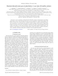
Refractometry based on a photonic crystal fiber interferometer - ICFO
Refractometry based on a photonic crystal fiber interferometer - ICFO
Refractometry based on a photonic crystal fiber interferometer - ICFO

You also want an ePaper? Increase the reach of your titles
YUMPU automatically turns print PDFs into web optimized ePapers that Google loves.
March 1, 2009 / Vol. 34, No. 5 / OPTICS LETTERS 617<br />
<str<strong>on</strong>g>Refractometry</str<strong>on</strong>g> <str<strong>on</strong>g>based</str<strong>on</strong>g> <strong>on</strong> a phot<strong>on</strong>ic <strong>crystal</strong> <strong>fiber</strong><br />
<strong>interferometer</strong><br />
Rajan Jha, 1, * Joel Villatoro, 1,3 G<strong>on</strong>çal Badenes, 1 and Valerio Pruneri 1,2<br />
1 <strong>ICFO</strong>-Institut de Ciències Fotòniques, Mediterranean Technology Park, 08860 Castelldefels (Barcel<strong>on</strong>a), Spain<br />
2 Also with ICREA-Institució Catalana de Recerca i Estudis Avançats, 08010, Barcel<strong>on</strong>a, Spain<br />
3 joel.villatoro@icfo.es<br />
*Corresp<strong>on</strong>ding author: rajaniitd@gmail.com<br />
Received December 15, 2008; revised January 21, 2009; accepted January 21, 2009;<br />
posted January 29, 2009 (Doc. ID 105376); published February 24, 2009<br />
We report a simple and compact modal <strong>interferometer</strong> for applicati<strong>on</strong>s in refractometry. The device c<strong>on</strong>sists<br />
of a stub of large-mode-area phot<strong>on</strong>ic <strong>crystal</strong> <strong>fiber</strong> (PCF) spliced between standard single-mode <strong>fiber</strong>s. In the<br />
splice regi<strong>on</strong>s the voids of the PCF are fully collapsed, thus allowing the coupling and recombinati<strong>on</strong> of PCF<br />
core and cladding modes. The device is highly stable over time, has low temperature sensitivity, and is suitable<br />
for measuring indices in the 1.330–1.440 range. The measure of the refractive index is carried out by<br />
m<strong>on</strong>itoring the shift of the interference pattern. © 2009 Optical Society of America<br />
OCIS codes: 060.2370, 060.5295, 120.3180, 280.4788.<br />
<str<strong>on</strong>g>Refractometry</str<strong>on</strong>g> is important from both the scientific<br />
and technological point of views owing to its numerous<br />
applicati<strong>on</strong>s. On the <strong>on</strong>e hand, the development<br />
of simple and compact refractometers is key for applicati<strong>on</strong>s<br />
in industrial processing, quality c<strong>on</strong>trol in<br />
food and beverage industries, etc. Refractive index<br />
sensors, <strong>on</strong> the other hand, are useful for studying<br />
different biological or chemical specimens. Optical <strong>fiber</strong><br />
refractometers and refractive index sensors are<br />
attractive, owing to their small size, flexibility in<br />
their design, immunity to electromagnetic interference,<br />
network compatibility, and the capability for remote<br />
and insitu measurement. To design a functi<strong>on</strong>al<br />
optical <strong>fiber</strong> refractometer <strong>on</strong>e needs to access the<br />
evanescent waves of the guided light without compromising<br />
the robustness of the device. In additi<strong>on</strong>, an<br />
ideal refractometer should be cost effective and able<br />
to measure indices over a broad range with high resoluti<strong>on</strong>.<br />
Refractometers <str<strong>on</strong>g>based</str<strong>on</strong>g> <strong>on</strong> tilted Bragg gratings,<br />
l<strong>on</strong>g-period gratings, and some modal <strong>interferometer</strong>s<br />
partially fulfill these c<strong>on</strong>diti<strong>on</strong>s, but they<br />
suffer from several drawbacks [1–11], such as their<br />
high cost and high sensitivity to temperature. Modal<br />
<strong>interferometer</strong>s are instead pr<strong>on</strong>e to drifts, because<br />
they are susceptible to perturbati<strong>on</strong>s of the mode coupling<br />
c<strong>on</strong>diti<strong>on</strong>s.<br />
In this Letter we propose a compact refractometer<br />
<str<strong>on</strong>g>based</str<strong>on</strong>g> <strong>on</strong> a robust all-<strong>fiber</strong> modal <strong>interferometer</strong> fabricated<br />
via straightforward and well-established fusi<strong>on</strong><br />
splicing. The device exploits the modal properties<br />
of phot<strong>on</strong>ic <strong>crystal</strong> <strong>fiber</strong>s (PCFs), while the<br />
interrogati<strong>on</strong> is carried out through pieces of standard<br />
optical <strong>fiber</strong>s. The fabricati<strong>on</strong> of the device is<br />
simple, since it involves <strong>on</strong>ly cleaving and splicing<br />
processes that can be carried out in a standard <strong>fiber</strong><br />
optics lab [12,13]. The range of refractive indices that<br />
can be measured is quite broad, from 1.33 (aqueous<br />
envir<strong>on</strong>ments) to 1.44 (biomolecules), with a resoluti<strong>on</strong><br />
of 2.910 −4 .<br />
Previously reported refractometers and index sensors<br />
<str<strong>on</strong>g>based</str<strong>on</strong>g> <strong>on</strong> PCF rely <strong>on</strong> tapering or grating technologies<br />
[14–18]. In most of these techniques infiltrati<strong>on</strong><br />
of sample into the holes of the PCF is needed. In<br />
our case, as it will be clear later, the refractive index<br />
measurement is possible through interacti<strong>on</strong> of the<br />
evanescent optical field and the material sample in<br />
the outer regi<strong>on</strong> of the PCF secti<strong>on</strong>. To build the device,<br />
a few centimeters of commercial PCF (LMA-8<br />
Crystal Fiber A/S) was fusi<strong>on</strong> spliced to a standard<br />
optical <strong>fiber</strong> (Corning SMF-28) with a c<strong>on</strong>venti<strong>on</strong>al<br />
splicing machine. The splicing was carried out in<br />
such a way that the voids of the PCF collapsed completely<br />
over a short regi<strong>on</strong>, typically less than<br />
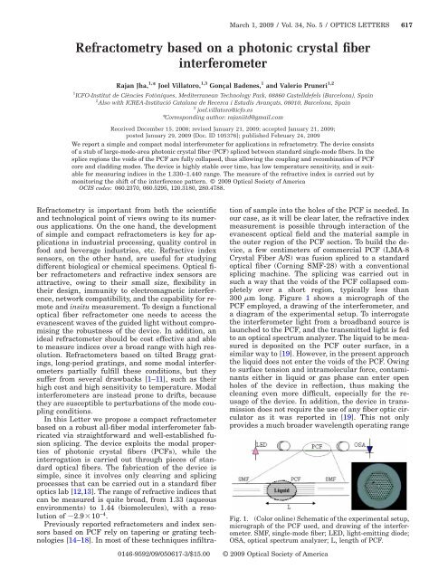
300 m l<strong>on</strong>g. Figure 1 shows a micrograph of the<br />
PCF employed, a drawing of the <strong>interferometer</strong>, and<br />
a diagram of the experimental setup. To interrogate<br />
the <strong>interferometer</strong> light from a broadband source is<br />
launched to the PCF, and the transmitted light is fed<br />
to an optical spectrum analyzer. The liquid to be measured<br />
is deposited <strong>on</strong> the PCF outer surface, in a<br />
similar way to [19]. However, in the present approach<br />
the liquid does not enter the voids of the PCF. Owing<br />
to surface tensi<strong>on</strong> and intramolecular force, c<strong>on</strong>taminants<br />
either in liquid or gas phase can enter open<br />
holes of the device in reflecti<strong>on</strong>, thus making the<br />
cleaning even more difficult, especially for the reusage<br />
of the device. In additi<strong>on</strong>, the device in transmissi<strong>on</strong><br />
does not require the use of any <strong>fiber</strong> optic circulator<br />
as it was reported in [19]. This not <strong>on</strong>ly<br />
provides a much broader wavelength operating range<br />
Fig. 1. (Color <strong>on</strong>line) Schematic of the experimental setup,<br />
micrograph of the PCF used, and drawing of the <strong>interferometer</strong>.<br />
SMF, single-mode <strong>fiber</strong>; LED, light-emitting diode;<br />
OSA, optical spectrum analyzer; L, length of PCF.<br />
0146-9592/09/050617-3/$15.00 © 2009 Optical Society of America
618 OPTICS LETTERS / Vol. 34, No. 5 / March 1, 2009<br />
(ten times larger) but also significantly reduces the<br />
complexity and cost of the device.<br />
To understand how the <strong>interferometer</strong> works let us<br />
analyze the guided beam when it travels from the<br />
SMF to the PCF (Fig. 1). The fundamental SMF<br />
mode begins to diffract when it enters a piece of solid<br />
glass, i.e., the collapsed PCF regi<strong>on</strong>. Because of diffracti<strong>on</strong><br />
the mode broadens allowing the excitati<strong>on</strong> of<br />
core and cladding modes in the PCF secti<strong>on</strong> [12,13].<br />
The propagati<strong>on</strong> c<strong>on</strong>stants of PCF core and cladding<br />
modes are different. Thus the modes accumulate a<br />
phase difference as they propagate al<strong>on</strong>g the PCF<br />
secti<strong>on</strong>. The phase difference depends <strong>on</strong> the wavelength<br />
of the guided light and also <strong>on</strong> the distance<br />
over which the modes travel (L, or length of PCF). After<br />
the PCF, the modes reach another solid piece of<br />
glass, i.e., the other collapsed end of PCF. They will<br />
thus further diffract and will be recombined through<br />
the filtering of the subsequent SMF. Therefore the<br />
transmissi<strong>on</strong> of our <strong>interferometer</strong> can be expressed<br />
as that of a two-mode <strong>interferometer</strong> [8]:<br />
T = I co + I cl +2I co I cl 1/2 cos2n ef L/,<br />
1<br />
where I co and I cl are the intensities of the core and<br />
cladding modes and n ef is the difference between<br />
the effective refractive indices of core and cladding<br />
modes. L is the length of PCF secti<strong>on</strong> over which the<br />
two modes travel. From Eq. (1) it can be seen that the<br />
transmissi<strong>on</strong> of our <strong>interferometer</strong> will exhibit a series<br />
of periodic maxima and minima. As an example<br />
in Fig. 2, we show the interference pattern over<br />
50 nm of a device fabricated with 80 mm of PCF. The<br />
periodic pattern indicates that interference occurs<br />
mainly between the fundamental core mode and <strong>on</strong>ly<br />
<strong>on</strong>e cladding mode. It can be noted that the maxima<br />
in these types of <strong>interferometer</strong>s will appear when<br />
2n ef L/=2m, m being an integer. Therefore the<br />
interference pattern exhibits peaks at wavelengths<br />
given by m n ef L/m. The separati<strong>on</strong> between c<strong>on</strong>secutive<br />
peaks (period) is given by P 2 /n ef L.<br />
The performance, stability, and temperature dependence<br />
of a modal <strong>interferometer</strong> depend critically<br />
<strong>on</strong> the element that excites and recombines the<br />
modes. In our <strong>interferometer</strong> the excitati<strong>on</strong> and recombinati<strong>on</strong><br />
of modes is carried out with permanent<br />
and stable splices. These do not degrade over time or<br />
with temperature; thus <strong>interferometer</strong>s with high<br />
stability are achievable. In Fig. 2, for example, we<br />
show the average drift as a functi<strong>on</strong> of time observed<br />
in a device fabricated with 80 mm of PCF. We tracked<br />
the positi<strong>on</strong> of all the peaks over 21 h with a <strong>fiber</strong><br />
Bragg interrogator with 10 pm resoluti<strong>on</strong>. The <strong>interferometer</strong><br />
was kept straight and isolated during the<br />
measurements. Shifts of less than 15 pm were observed<br />
indicating the high stability that is important<br />
for sensing applicati<strong>on</strong>s. As it is shown in Fig. 2, the<br />
temperature dependence in the range of<br />
24°C–240°C was also studied. Note that for a<br />
change in temperature of more than 200°C, the total<br />
shift in interference pattern is 1.5 nm, thereby suggesting<br />
very low temperature dependence. It was<br />
typically in 5–8 pm/ °C range depending up<strong>on</strong> the<br />
different device parameters.<br />
Note that the evanescent waves of cladding modes<br />
reach the external surface of the PCF, thus making<br />
possible the interacti<strong>on</strong> with liquids or coatings. In<br />
our <strong>interferometer</strong>s the interacti<strong>on</strong> is solely with the<br />
cladding modes, since the core mode is isolated from<br />
the external envir<strong>on</strong>ment. The interacti<strong>on</strong> of the<br />
cladding modes with the external index changes n ef ,<br />
and c<strong>on</strong>sequently the phase difference. As a result,<br />
the positi<strong>on</strong> of the interference peaks and valleys<br />
change, or equivalently the interference pattern<br />
shifts. Therefore, by m<strong>on</strong>itoring the interference pattern<br />
wavelength shift, <strong>on</strong>e can infer the external refractive<br />
index and its changes. For example, Figs. 3<br />
and 4 show the transmissi<strong>on</strong> spectra in the<br />
1490–1590 nm range of two <strong>interferometer</strong>s, L<br />
=17 mm and 32 mm, respectively, surrounded by air<br />
(refractive index of 1) and liquids with higher indices.<br />
The shifts observed in both <strong>interferometer</strong>s depended<br />
<strong>on</strong> the external index. The figures also show the shift<br />
measured in the 1490–1590 nm wavelength range as<br />
a functi<strong>on</strong> of the external index in both devices. Deviati<strong>on</strong>s<br />
from the fitting are justified, since these ex-<br />
Fig. 2. (Color <strong>on</strong>line) Shift in interference pattern as a<br />
functi<strong>on</strong> of temperature. Top inset, drift as a functi<strong>on</strong> of<br />
time observed in 80 mm l<strong>on</strong>g <strong>interferometer</strong>. Bottom inset,<br />
interference pattern of the same device over 50 nm in air.<br />
Fig. 3. (Color <strong>on</strong>line) Shift of the interference pattern as a<br />
functi<strong>on</strong> of the external refractive index observed in a device<br />
with L=17 mm. The solid circles are experimental<br />
data, and the c<strong>on</strong>tinuous curve is a fitting to the data.<br />
Shiftnm=3.29163+AexpRI/0.02659 shows the expressi<strong>on</strong><br />
that fits to the experimental points with A=4.75282<br />
10 −23 . Inset, transmissi<strong>on</strong> spectra of the device in air and<br />
water.
March 1, 2009 / Vol. 34, No. 5 / OPTICS LETTERS 619<br />
Fig. 4. (Color <strong>on</strong>line) Shift of the interference pattern as a<br />
functi<strong>on</strong> of the external refractive index observed in a device<br />
with L=32 mm. The solid circles are experimental<br />
data, and the c<strong>on</strong>tinuous curve is a fitting to the data.<br />
Shiftnm=2.05046+BexpRI/0.02503 shows the expressi<strong>on</strong><br />
that fits to the experimental points with B=2.3650<br />
10 −24 . Inset, transmissi<strong>on</strong> spectra of the device in air and<br />
in liquid with an index of 1.380.<br />
perimental points were taken from not perfectly<br />
regular interference patterns.<br />
Cargille oils with calibrated indices were used in<br />
the experiments. Between c<strong>on</strong>secutive measurements<br />
the surface of the PCF was cleaned with acet<strong>on</strong>e<br />
and then dried with nitrogen to ensure similar<br />
c<strong>on</strong>diti<strong>on</strong>s in each measurement. It can be observed<br />
from Figs. 3 and 4 that the shift of the interference is<br />
more prominent as the external index gets closer to<br />
that of the <strong>fiber</strong>. In this regard our <strong>interferometer</strong> behaves<br />
in a manner similar to those <str<strong>on</strong>g>based</str<strong>on</strong>g> <strong>on</strong> gratings<br />
[1–8]. L<strong>on</strong>ger devices may be more sensitive owing to<br />
a combinati<strong>on</strong> of l<strong>on</strong>ger interacti<strong>on</strong> lengths and<br />
sharper fringes, but shifts of more than <strong>on</strong>e period in<br />
a practical situati<strong>on</strong> may be unwelcome. Our devices<br />
exhibit maximum sensitivity for indices close to that<br />
of the glass of the PCF. Above that value, the cladding<br />
mode becomes effectively a radiati<strong>on</strong> mode and<br />
the interference pattern disappears. The maximum<br />
resoluti<strong>on</strong> of the 32-mm-l<strong>on</strong>g <strong>interferometer</strong> in the<br />
1.38–144 index range was found to be 2.910 −4 ,<br />
which is comparable to that of commercial refractometers.<br />
However, at indices in the 1.33–1.38 range<br />
the resoluti<strong>on</strong> is 210 −3 . To calculate these numbers<br />
it was assumed that a shift of 100 pm can be resolved<br />
by the detecti<strong>on</strong> unit (although the FBG interrogator<br />
that we used has a resoluti<strong>on</strong> of 10 pm). It is<br />
important to point out that in sensing devices <str<strong>on</strong>g>based</str<strong>on</strong>g><br />
<strong>on</strong> shift of fringes, the minimum detectable shift is<br />
related with the width (FWHM) of them. In case of<br />
broad interference fringes that limit is generally<br />
FWHM/100. In our case, <strong>interferometer</strong>s with<br />
10-nm-wide fringes can be fabricated, which justify<br />
the above numbers. At shorter wavelengths the resoluti<strong>on</strong><br />
is slightly lower in both refractive index<br />
ranges. Note that a temperature gradient of approximately<br />
20°C will be required to cause a shift of<br />
100 pm; therefore temperature compensati<strong>on</strong> may<br />
not be needed in this type of refractometers if they<br />
are used in normal envir<strong>on</strong>ments.<br />
In c<strong>on</strong>clusi<strong>on</strong>, a compact and simple modal <strong>interferometer</strong><br />
that operates over a wide wavelength<br />
range has been proposed for refractive index measurements.<br />
Its fabricati<strong>on</strong> c<strong>on</strong>sists of large-modearea<br />
PCF of different lengths spliced between standard<br />
single-mode <strong>fiber</strong>s. The refractometric<br />
properties of our <strong>interferometer</strong>s were investigated<br />
with known liquids in the refractive index range of<br />
1.33–1.45. Sensing <str<strong>on</strong>g>based</str<strong>on</strong>g> <strong>on</strong> refractive index changes<br />
is also feasible. For example, the PCF can be coated<br />
with polymeric, sol gel, or metallic films with literally<br />
any index and thickness. Changes in the film refractive<br />
index caused by biological, chemical, or physical<br />
parameters will cause a detectable shift in the interference<br />
pattern.<br />
This work was carried out with the financial support<br />
of the Ministerio de Educación y Ciencia (Spain)<br />
through grant TEC2006-10665/MIC, “Ramón y Cajal”<br />
program, and the European Commissi<strong>on</strong> through the<br />
European Network of Excellence PHOREMOST<br />
(FP6-511616).<br />
References<br />
1. G. Laff<strong>on</strong>t and P. Ferdinand, Meas. Sci. Technol. 12,<br />
765 (2001).<br />
2. K. Zhou, L. Zhang, X. Chen, and I. Benni<strong>on</strong>, Opt. Lett.<br />
31, 1193 (2006).<br />
3. B. H. Lee, Y. Liu, S. B. Lee, S. S. Choi, and J. N. Jang,<br />
Opt. Lett. 22, 1769 (1997).<br />
4. T. Zhu, Y. J. Rao, and Q. J. Mo, IEEE Phot<strong>on</strong>. Technol.<br />
Lett. 17, 2700 (2005).<br />
5. T. Allsop, R. Reeves, D. J. Webb, I. Benni<strong>on</strong>, and R.<br />
Neal, Rev. Sci. Instrum. 73, 1702 (2002).<br />
6. P. L. Swart, Meas. Sci. Technol. 15, 1576 (2004).<br />
7. D. W. Kim, Y. Zhang, K. L. Cooper, and A. Wang, Appl.<br />
Opt. 44, 5368 (2005).<br />
8. P. Pilla, P. Foglia Manzillo, M. Giordano, M. L. Korwin-<br />
Pawlowski, W. J. Bock, and A. Cusano, Opt. Express<br />
16, 9765 (2008).<br />
9. Y. Jung, S. Kim, D. Lee, and K. Oh, Meas. Sci. Technol.<br />
17, 1129 (2006).<br />
10. Q. Wang and G. Farrell, Opt. Lett. 31, 317 (2006).<br />
11. Z. Tian, S. S. Yam, and H. Loock, Opt. Lett. 33, 1105<br />
(2008).<br />
12. J. Villatoro, V. P. Minkovich, V. Pruneri, and G.<br />
Badenes, Opt. Express 15, 1491 (2007).<br />
13. J. Villatoro, V. Finazzi, V. P. Minkovich, V. Pruneri, and<br />
G. Badenes, Appl. Phys. Lett. 91, 091109 (2007).<br />
14. V. Minkovich, J. Villatoro, D. M<strong>on</strong>z<strong>on</strong>-Hernandez, S.<br />
Calixto, A. Sotsky, and L. Sotskaya, Opt. Express 13,<br />
7609 (2005).<br />
15. M. C. P. Huy, G. Laff<strong>on</strong>t, V. Dewynter, P. Ferdinand, L.<br />
Lab<strong>on</strong>te, D. Pagnoux, P. Roy, W. Blanc, and B.<br />
Dussardier, Opt. Express 14, 10359 (2006).<br />
16. Y. Zhu, Z. He, and H. Du, Sens. Actuators B 131, 265<br />
(2008).<br />
17. L. Rindorf and O. Bang, Opt. Lett. 33, 563 (2008).<br />
18. C. Chen, A. Lar<strong>on</strong>che, G. Bouwmans, L. Bigot, Y.<br />
Quiquempois, and J. Albert, Opt. Express 16, 9645<br />
(2008).<br />
19. R. Jha, J. Villatoro, and G. Badenes, Appl. Phys. Lett.<br />
93, 191106 (2008).