FCOVF6100 (PDF)
FCOVF6100 (PDF)
FCOVF6100 (PDF)

You also want an ePaper? Increase the reach of your titles
YUMPU automatically turns print PDFs into web optimized ePapers that Google loves.
<strong>FCOVF6100</strong><br />
®<br />
Features:<br />
Industry Standard<br />
ASIC-Based Design<br />
Variable frequency<br />
range of operation:<br />
30-140 Hz (nominal)<br />
(others available)<br />
Fully Connectorized<br />
Independently<br />
Configurable<br />
Soft-Start and<br />
Soft-Stop<br />
Isolated Gate Drive<br />
Circuitry<br />
Phase Loss<br />
Protection<br />
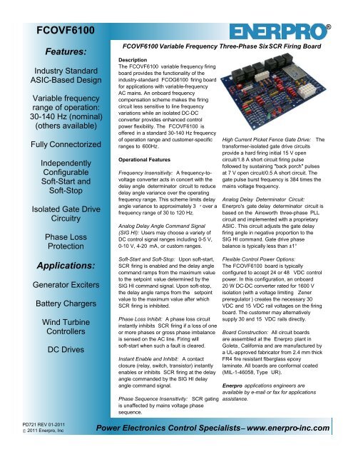
<strong>FCOVF6100</strong> Variable Frequency Three-Phase SixSCR Firing Board<br />
Description<br />
The <strong>FCOVF6100</strong> variable frequency firing<br />
board provides the functionality of the<br />
industry-standard FCOG6100 firing board<br />
for applications with variable-frequency<br />
AC mains. An onboard frequency<br />
compensation scheme makes the firing<br />
circuit less sensitive to line frequency<br />
variations while an isolated DC-DC<br />
converter provides enhanced control<br />
power flexibility. The <strong>FCOVF6100</strong> is<br />
offered in a standard 30-140 Hz frequency<br />
of operation range and customer-specific<br />
ranges to 600Hz.<br />
Operational Features<br />
Frequency Insensitivity: A frequency-tovoltage<br />
converter acts in concert with the<br />
delay angle determinator circuit to reduce<br />
delay angle variance over the operating<br />
frequency range. This scheme limits delay<br />
angle variance to approximately 3 over a<br />
frequency range of 30 to 120 Hz.<br />
Analog Delay Angle Command Signal<br />
(SIG HI): Users may choose a variety of<br />
DC control signal ranges including 0-5 V,<br />
0-10 V, 4-20 mA, or custom ranges.<br />
High Current Picket Fence Gate Drive: The<br />
transformer-isolated gate drive circuits<br />
provide a hard firing initial 15 V open<br />
circuit/1.8 A short circuit firing pulse<br />
followed by sustaining "back porch" pulses<br />
at 7 V open circuit/0.5 A short circuit. The<br />
gate pulse burst frequency is 384 times the<br />
mains voltage frequency.<br />
Analog Delay Determinator Circuit:<br />
Enerpro's gate delay determinator circuit is<br />
based on the Ainsworth three-phase PLL<br />
circuit and implemented with a proprietary<br />
ASIC. This circuit adjusts the gate delay<br />
firing angle in negative proportion to the<br />
SIG HI command. Gate drive phase<br />
balance is typically less than ±1°<br />
Applications:<br />
Generator Exciters<br />
Battery Chargers<br />
Wind Turbine<br />
Controllers<br />
DC Drives<br />
Soft-Start and Soft-Stop: Upon soft-start,<br />
SCR firing is enabled and the delay angle<br />
command ramps from the maximum value<br />
to the setpoint value determined by the<br />
SIG HI command signal. Upon soft-stop,<br />
the delay angle ramps from the setpoint<br />
value to the maximum value after which<br />
SCR firing is inhibited.<br />
Phase Loss Inhibit: A phase loss circuit<br />
instantly inhibits SCR firing if a loss of one<br />
or more phases or gross phase imbalance<br />
is sensed on the AC line. Firing will<br />
soft-start when such a fault is cleared.<br />
Instant Enable and Inhibit: A contact<br />
closure (relay, switch, transistor) instantly<br />
enables or inhibits SCR firing at the delay<br />
angle commanded by the SIG HI delay<br />
angle command signal.<br />
Phase Sequence Insensitivity: SCR gating<br />
is unaffected by mains voltage phase<br />
sequence.<br />
Flexible Control Power Options:<br />
The <strong>FCOVF6100</strong> board is typically<br />
configured to accept 24 or 48 VDC control<br />
power. In this configuration, an onboard<br />
20 W DC-DC converter rated for 1600 V<br />
isolation (with a voltage limiting Zener<br />
preregulator ) creates the necessary 30<br />
VDC and 15 VDC rail voltages on the firing<br />
board. The customer may alternatively<br />
supply 30 and 15 VDC rails directly.<br />
Board Construction: All circuit boards<br />
are assembled at the Enerpro plant in<br />
Goleta, California and are manufactured by<br />
a UL-approved fabricator from 2.4 mm thick<br />
FR4 fire resistant fiberglass epoxy<br />
laminate. All boards are conformal coated<br />
(MIL-1-46058, Type UR).<br />
Enerpro applications engineers are<br />
available by e-mail or fax for applications<br />
assistance.<br />
PD721 REV 01-2011<br />
2011 Enerpro, Inc<br />
Power Electronics Control Specialists<br />
www.enerpro-inc.com
<strong>FCOVF6100</strong><br />
Product Datasheet<br />
Maximum Ratings<br />
AC mains voltage<br />
600 Vac<br />
Pulse transformer hipot<br />
3500 Vac (60 seconds)<br />
Operating temperature range<br />
-5 C to 85 C<br />
Board supply voltage without DC-DC converter 30 and 15 VDC supplies ± 5% max<br />
Board supply input range with DC-DC<br />
18 - 36 VDC<br />
converter, 24 VDC nominal input<br />
Board supply input range with DC-DC<br />
converter, 48 VDC nominal input<br />
36 - 75 VDC<br />
Board ac supply voltage<br />
28 Vac (24 Vac nominal)<br />
12 V regulator output current 20 mA (Note 1)<br />
5 V reference output current 5 mA (Note 1)<br />
Auxiliary control power available from 30 V 10 W (DC-DC<br />
output<br />
Delay angle range 10° 170°<br />
Characteristics<br />
Delay angle command signal<br />
(SIG HI)<br />
Delay angle reference phase shift<br />
Control signal isolation from ground<br />
Gate delay steady-state transfer function<br />
Gate delay dynamic transfer function<br />
bandwidth<br />
Gate drive phase balance<br />
Lock acquisition time<br />
Soft-start/stop time<br />
Phase rotation effect<br />
Phase loss inhibit<br />
Power-on inhibit<br />
Instant/soft inhibit/enable inputs<br />
SCR gate pulse waveform<br />
0-5, 0.85-5.85, 0-10, 1-2 V<br />
4-20 mA<br />
Or as specified<br />
-60° (or application-specific)<br />
653 k<br />
Delay angle inversely proportional<br />
to delay angle command SIG HI<br />
-3 dB at 119 Hz, phase shift -45° at<br />
68 Hz<br />
±1° (max)<br />
30 ms (typ)<br />
0.05 - 20.0 s, independently<br />
configurable<br />
None<br />
Automatic<br />
Automatic<br />
Dry contact<br />
120° burst or<br />
2-30° bursts, 30° spaced<br />
Gate pulse burst frequency<br />
384 times line frequency<br />
Initial gate pulse open circuit voltage 15 V (Note 1)<br />
Sustaining gate pulse open circuit voltage 7.0 V (Note 1)<br />
Initial gate drive short circuit current 2.0 A (Note 1 and 2)<br />
Sustaining gate drive short circuit current 0.5 A (Note 1 and 2<br />
Short-circuit gate drive current rise time 1.0 A/ s (Note 1 and 2)<br />
Board dimensions 191 x 152 x 35 mm (L x W x D)<br />
Minimum creepage distance to ac mains<br />
With onboard phase references<br />
With phase references entering on J6<br />
Conformal Coating<br />
NOTES<br />
1 Assumes nominal 30 V control power<br />
2 Assumes a purely resistive gate load of 1.0<br />
13 mm<br />
10 mm<br />
per MIL-1-46058, Type UR<br />
Ordering Guide<br />
Parameter Description Code<br />
SCR Circuit<br />
Type<br />
Parallel<br />
SCRs<br />
Mains<br />
Frequency<br />
Command<br />
Signal<br />
Used with<br />
Regulator<br />
Board<br />
SCR Mains<br />
Voltage<br />
Control<br />
Power<br />
Phase<br />
References<br />
01 Controller<br />
02 Converter<br />
0 No<br />
1 Yes (Note 1)<br />
01 30 - 140 Hz<br />
02 Other, Specify (Note 2)<br />
1 0 - 5 V<br />
2 0.85 - 5.85 V<br />
3 0 - 10 V<br />
4 1 - 2 V<br />
5 4 - 20 mA<br />
6 Other - Specify<br />
0 No<br />
1 Horizontal Header<br />
2 Vertical Header<br />
XX Specify (Note 3)<br />
0 Omit DC/DC<br />
Converter-Specify<br />
(Note 4)<br />
1 With 24 Volt DC/DC<br />
Converter<br />
2 With 48 Volt DC/DC<br />
Converter<br />
1 On-board<br />
2 External (Note 5)<br />
Notes<br />
1 Auxiliary firing board required for parallel SCRs<br />
2 Specify desired mains frequency range.<br />
3 Specify code as mains voltage divided by 10.<br />
Example: 480 V / 10 = 48<br />
4 Customer must supply regulated 30 and 15 VDC<br />
for control power.<br />
5 Connect ac mains via J6 to provide phase<br />
references.<br />
Enerpro, Inc.<br />
5780 Thornwood Drive<br />
Goleta, CA 93117 (USA)<br />
Tel: (805) 683-2114<br />
(800) 576-2114<br />
Fax: (805) 964-0798<br />
info@enerpro-inc.com<br />
www.enerpro-inc.com<br />
®<br />
PD721 REV 01-2011<br />
2011 Enerpro, Inc