Load Transfer by an implant in a sinus-grafted Maxillary ... - Id-sc.com
Load Transfer by an implant in a sinus-grafted Maxillary ... - Id-sc.com
Load Transfer by an implant in a sinus-grafted Maxillary ... - Id-sc.com

Create successful ePaper yourself
Turn your PDF publications into a flip-book with our unique Google optimized e-Paper software.
FANUSCU ET AL<br />
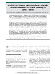
Fig 1 Cross-section of alveolar bone with s<strong>in</strong>us cavity <strong>an</strong>d walls<br />
<strong>in</strong> the posterior maxilla from hum<strong>an</strong> cadaver. SW = s<strong>in</strong>us walls;<br />
SB = s<strong>in</strong>us bone; AB = alveolar bone.<br />
SW<br />
SB<br />
AB<br />
the edentulous posterior maxilla, with m<strong>in</strong>eralized<br />
tissue volume of the latter r<strong>an</strong>g<strong>in</strong>g from 17.1% to<br />
26.7%. 19<br />
Premature load<strong>in</strong>g <strong>an</strong>d/or overload<strong>in</strong>g might be<br />
signific<strong>an</strong>t concerns <strong>in</strong> s<strong>in</strong>us graft cases, s<strong>in</strong>ce different<br />
graft materials <strong>an</strong>d their maturation patterns<br />
c<strong>an</strong> have variable load-bear<strong>in</strong>g capacities. Biomech<strong>an</strong>ically,<br />
control of the load tr<strong>an</strong>sfer to bone surround<strong>in</strong>g<br />
the impl<strong>an</strong>ts plays <strong>an</strong> import<strong>an</strong>t role <strong>in</strong><br />
the long-term success of impl<strong>an</strong>t therapy. 20 Several<br />
studies have reported that appropriately controlled<br />
loads c<strong>an</strong> stimulate bone remodel<strong>in</strong>g around<br />
impl<strong>an</strong>ts, 21,22 whereas excessive stresses cause marg<strong>in</strong>al<br />
bone resorption. 23–25<br />
The purpose of this study was to <strong>in</strong>vestigate the<br />
stress distribution <strong>in</strong> bone around <strong>an</strong> impl<strong>an</strong>t placed<br />
<strong>in</strong> a posterior atrophic maxilla with a simulated<br />
s<strong>in</strong>us graft <strong>by</strong> use of a <strong>com</strong>posite photoelastic<br />
model.<br />
MATERIALS AND METHODS<br />
grafts. There was no <strong>in</strong>dication of the superiority of<br />
a particular protocol or material. However, there<br />
was a statistically signific<strong>an</strong>t difference <strong>in</strong> impl<strong>an</strong>t<br />
loss when available residual or native bone was 4<br />
mm or less as opposed to 5 mm or greater.<br />
A <strong>com</strong>plex structure consist<strong>in</strong>g of bone with<br />
vary<strong>in</strong>g stiffness c<strong>an</strong> be found around impl<strong>an</strong>ts<br />
placed <strong>in</strong> the posterior maxilla with <strong>grafted</strong><br />
s<strong>in</strong>us(es). A crucial process that leads to the stability<br />
of osseo<strong>in</strong>tegrated impl<strong>an</strong>ts is m<strong>in</strong>eralization of the<br />
bone adjacent to the impl<strong>an</strong>t surface. Native bone,<br />
which is a critical factor <strong>in</strong> establish<strong>in</strong>g <strong>an</strong>d ma<strong>in</strong>ta<strong>in</strong><strong>in</strong>g<br />
osseo<strong>in</strong>tegration, consists of crestal cortical<br />
bone, c<strong>an</strong>cellous bone, <strong>an</strong>d s<strong>in</strong>us floor cortical bone.<br />
The contribution of the <strong>grafted</strong> bone to the establishment<br />
<strong>an</strong>d ma<strong>in</strong>ten<strong>an</strong>ce of impl<strong>an</strong>t stability is not<br />
yet understood. <strong>Load</strong>-bear<strong>in</strong>g characteristics of<br />
<strong>grafted</strong> bone depend on the graft material <strong>an</strong>d its<br />
maturation process. Several studies have <strong>in</strong>vestigated<br />
the total volume of hard tissue with<strong>in</strong> various<br />
<strong>grafted</strong> s<strong>in</strong>uses to predict long-term impl<strong>an</strong>t stability.<br />
Accord<strong>in</strong>g to histologic <strong>an</strong>alysis, the vital m<strong>in</strong>eralized<br />
tissue volume of the <strong>grafted</strong> s<strong>in</strong>us r<strong>an</strong>ged<br />
from 26% to 69% when only autogenous bone was<br />
used. 12–15 The r<strong>an</strong>ge of vital m<strong>in</strong>eralized tissue volume<br />
was 5% to 45% when <strong>an</strong>y other graft material<br />
or <strong>com</strong>b<strong>in</strong>ations of materials were used. 8,12,16–18 It<br />
also should be noted that the m<strong>in</strong>eralized tissue volume<br />
of <strong>grafted</strong> s<strong>in</strong>uses has been reported as relatively<br />
greater th<strong>an</strong> that of native c<strong>an</strong>cellous bone <strong>in</strong><br />
A <strong>com</strong>posite photoelastic model simulat<strong>in</strong>g a unilateral<br />
atrophic edentulous posterior maxilla was fabricated<br />
for quasi–3-dimensional test<strong>in</strong>g <strong>an</strong>d <strong>an</strong>alysis<br />
(Fig 2a). Individual photoelastic simul<strong>an</strong>ts with different<br />
stiffnesses were used for cortical bone (PLM-<br />
1, Measurements Group, Raleigh, NC) <strong>an</strong>d c<strong>an</strong>cellous<br />
bone (PL-2, Measurements Group). Simulated<br />
crestal cortical bone, c<strong>an</strong>cellous bone, <strong>an</strong>d s<strong>in</strong>us<br />
floor cortical bone were fabricated <strong>in</strong> 1-mm, 3.5-<br />
mm, <strong>an</strong>d 0.5-mm heights, respectively (Fig 2b).<br />
Therefore, the total height of simulated native bone<br />
was 5.0 mm.<br />
A st<strong>an</strong>dard threaded impl<strong>an</strong>t, 3.75 mm <strong>in</strong> diameter<br />
<strong>an</strong>d 13 mm <strong>in</strong> length (Impl<strong>an</strong>t Innovations,<br />
Palm Beach Gardens, FL), was <strong>in</strong>corporated <strong>in</strong>to<br />
the model. Photoelastic res<strong>in</strong>s represent<strong>in</strong>g the<br />
native bone <strong>com</strong>ponents were poured directly<br />
around the impl<strong>an</strong>t <strong>an</strong>d allowed to cure <strong>com</strong>pletely.<br />
An experimental photoelastic res<strong>in</strong> (modified PLM-<br />
1, Measurement Group) represent<strong>in</strong>g the graft was<br />
then placed <strong>in</strong>to the simulated maxillary s<strong>in</strong>us cavity<br />
(Fig 2b). Several res<strong>in</strong> hardener ratios of PLM-1<br />
were tested previously to establish a r<strong>an</strong>ge of stiffness<br />
values. Beams of modified PLM-1, 4.5 2.8 <br />
30 mm, were tested <strong>in</strong> flexure on <strong>an</strong> Instron test<br />
mach<strong>in</strong>e (Instron, C<strong>an</strong>ton, MA). Three beams of<br />
each formulation were tested at 3, 4, 5, 6, 7, <strong>an</strong>d 10<br />
days. From the results of these tests, a formulation<br />
with a ch<strong>an</strong>ge <strong>in</strong> stiffness over time was selected to<br />
simulate the mech<strong>an</strong>ical response of either a bone<br />
graft matur<strong>in</strong>g over time or of different qualities of<br />
graft materials (Fig 3).<br />
668 Volume 18, Number 5, 2003