

Category 6 and Category 7 Permanent Link and Channel Testing ...
Category 6 and Category 7 Permanent Link and Channel Testing ...
Category 6 and Category 7 Permanent Link and Channel Testing ...

Create successful ePaper yourself
Turn your PDF publications into a flip-book with our unique Google optimized e-Paper software.
<strong>Category</strong> 6 <strong>and</strong> <strong>Category</strong> 7 <strong>Permanent</strong> <strong>Link</strong> <strong>and</strong> <strong>Channel</strong> <strong>Testing</strong> with<br />
the IDEAL LANTEK 6/7 LAN Cable Testers<br />
Introduction<br />
IDEAL has taken a fresh approach in designing the <strong>Link</strong> Adapters for the LANTEK 6/7 LAN Cable testers. When you first open the case of these products,<br />
you will immediately notice that traditional <strong>Permanent</strong> <strong>Link</strong> <strong>and</strong> Calibration Adapters are gone. For the LANTEK 6, you will find two <strong>Category</strong> 6 Test<br />
Adapters <strong>and</strong> two Reference Patchcords with <strong>Category</strong> 6 plugs at both ends.<br />
In the LANTEK 7 case, there are two <strong>Category</strong> 7 Tera Test Adapters <strong>and</strong> two sets of Reference Patchcords. The first set contains Reference Patchcords with<br />
Tera plugs at both ends. The second set contains Reference Patchcords with Tera plugs at one end <strong>and</strong> <strong>Category</strong> 6 plugs at the other end. (Note: IDEAL<br />
is working closely with Nexans to develop a set of Test Adapters utilizing the Nexans GG45 jack. The date for availability of these Test Adapters has not<br />
yet been determined.)<br />
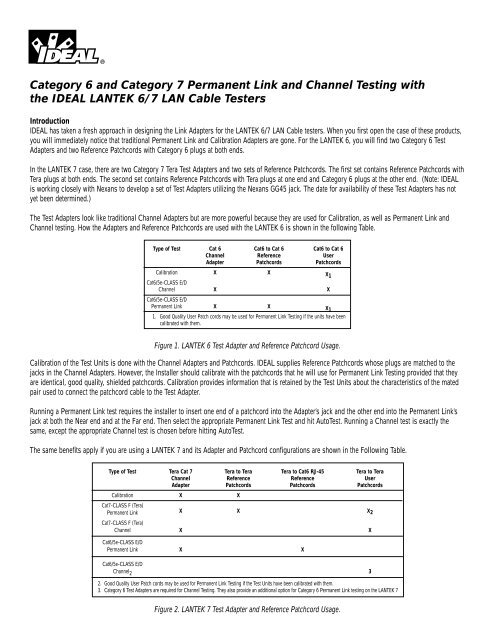
The Test Adapters look like traditional <strong>Channel</strong> Adapters but are more powerful because they are used for Calibration, as well as <strong>Permanent</strong> <strong>Link</strong> <strong>and</strong><br />
<strong>Channel</strong> testing. How the Adapters <strong>and</strong> Reference Patchcords are used with the LANTEK 6 is shown in the following Table.<br />
Type of Test Cat 6 Cat6 to Cat 6 Cat6 to Cat 6<br />
<strong>Channel</strong> Reference User<br />
Adapter Patchcords Patchcords<br />
Calibration X X X 1<br />
Cat6/5e-CLASS E/D<br />
<strong>Channel</strong> X X<br />
Cat6/5e-CLASS E/D<br />
<strong>Permanent</strong> <strong>Link</strong> X X X 1<br />
1. Good Quality User Patch cords may be used for <strong>Permanent</strong> <strong>Link</strong> <strong>Testing</strong> if the units have been<br />
calibrated with them.<br />
Figure 1. LANTEK 6 Test Adapter <strong>and</strong> Reference Patchcord Usage.<br />
Calibration of the Test Units is done with the <strong>Channel</strong> Adapters <strong>and</strong> Patchcords. IDEAL supplies Reference Patchcords whose plugs are matched to the<br />
jacks in the <strong>Channel</strong> Adapters. However, the Installer should calibrate with the patchcords that he will use for <strong>Permanent</strong> <strong>Link</strong> <strong>Testing</strong> provided that they<br />
are identical, good quality, shielded patchcords. Calibration provides information that is retained by the Test Units about the characteristics of the mated<br />
pair used to connect the patchcord cable to the Test Adapter.<br />
Running a <strong>Permanent</strong> <strong>Link</strong> test requires the installer to insert one end of a patchcord into the Adapter’s jack <strong>and</strong> the other end into the <strong>Permanent</strong> <strong>Link</strong>’s<br />
jack at both the Near end <strong>and</strong> at the Far end. Then select the appropriate <strong>Permanent</strong> <strong>Link</strong> Test <strong>and</strong> hit AutoTest. Running a <strong>Channel</strong> test is exactly the<br />
same, except the appropriate <strong>Channel</strong> test is chosen before hitting AutoTest.<br />
The same benefits apply if you are using a LANTEK 7 <strong>and</strong> its Adapter <strong>and</strong> Patchcord configurations are shown in the Following Table.<br />
Type of Test Tera Cat 7 Tera to Tera Tera to Cat6 RJ-45 Tera to Tera<br />
<strong>Channel</strong> Reference Reference User<br />
Adapter Patchcords Patchcords Patchcords<br />
Calibration X X<br />
Cat7-CLASS F (Tera)<br />
<strong>Permanent</strong> <strong>Link</strong> X X X 2<br />
Cat7-CLASS F (Tera)<br />
<strong>Channel</strong> X X<br />
Cat6/5e-CLASS E/D<br />
<strong>Permanent</strong> <strong>Link</strong> X X<br />
Cat6/5e-CLASS E/D<br />
<strong>Channel</strong> 2 3<br />
2. Good Quality User Patch cords may be used for <strong>Permanent</strong> <strong>Link</strong> <strong>Testing</strong> if the Test Units have been calibrated with them.<br />
3. <strong>Category</strong> 6 Test Adapters are required for <strong>Channel</strong> <strong>Testing</strong>. They also provide an additional option for <strong>Category</strong> 6 <strong>Permanent</strong> <strong>Link</strong> testing on the LANTEK 7<br />
Figure 2. LANTEK 7 Test Adapter <strong>and</strong> Reference Patchcord Usage.
The Table shows several additional benefits of this new Adapter design. If the testing plug shows wear, just replace the patchcord, not the Adapter, <strong>and</strong><br />
recalibrate. And perhaps even more beneficial, good quality 2-meter patchcords with plugs matching the connectors of the installation may be used for<br />
<strong>Permanent</strong> <strong>Link</strong> testing. Simply calibrate the LANTEK units with the patchcords, select the appropriate <strong>Channel</strong> or <strong>Permanent</strong> <strong>Link</strong> Test <strong>and</strong> begin testing.<br />
The Design<br />
So, just how can you use the same adapter for both <strong>Permanent</strong> <strong>Link</strong> <strong>and</strong> <strong>Channel</strong> testing? A very simplistic explanation is that IDEAL has simply replaced<br />
the soldered connection that connects the Test Lead to the Adapter with a mated pair connection. A look at the components contributing to an overall<br />
Loss measurement are shown in the figure below:<br />
Figure 3. Loss Components of a Total <strong>Link</strong><br />
To properly report the Loss Effects of a <strong>Permanent</strong> <strong>Link</strong> or <strong>Channel</strong>, all of the Loss Effects of each of the shown components must be known.<br />
Then, when the overall raw Loss Effects are measured, the background loss effects of the Test Units, Adapters, <strong>and</strong> the Test Unit/Adapter Interfaces are<br />
subtracted to give the <strong>Channel</strong> Losses.<br />
If the <strong>Permanent</strong> <strong>Link</strong> Losses are desired, the Loss effects of the Test Lead patchcords <strong>and</strong> the mated pair making up the Adapter/patchcord Interface are<br />
subtracted from the overall <strong>Channel</strong> Losses.<br />
The data is collected into a series of fourteen 8 x 8 Matrices for each of the components. A more detailed description of these matrices is provided in<br />
Appendix A.<br />
So, each time AutoTest is hit, the tester looks for the test that was selected (<strong>Channel</strong> or <strong>Permanent</strong> <strong>Link</strong>) <strong>and</strong> executes the appropriate matrix operation to<br />
report out the desired results.<br />
RECAPPING THE BENEFITS<br />
Reduction of the Cost of ownership.<br />
By using the same Adapter for Cat 6 <strong>Permanent</strong> <strong>Link</strong> testing, Cat 5e <strong>Channel</strong> <strong>Testing</strong> <strong>and</strong> Tester Calibration, LanTek 6 buyers have four less Adapters to<br />
buy. And because the same Adapter can be used for Cat 7 Tera <strong>Channel</strong> testing <strong>and</strong> Cat 7 Tera <strong>Permanent</strong> <strong>Link</strong> <strong>Testing</strong>, LanTek 7 users also have four less<br />
Adapters to buy. And when a Connector vendor requires that the test be run with Adapters using the vendor’s proprietary plug, chances are that only a<br />
new Reference Patchcord had to be purchased, <strong>and</strong> not new Adapters.<br />
Reduction in Product Complexity.<br />
With the LanTek 6 <strong>and</strong> LanTek 7, there are fewer Adapters to manage. That means less confusion when ordering, <strong>and</strong> less temptation to leave some of the<br />
adapters "back at the office, including the one you currently need.<br />
Reduction in Adapter connector wear<br />
The connector between the Adapter <strong>and</strong> the test unit is a 160-pin connector. IDEAL has reduced the wear on this connector in two ways: First, the Adapter<br />
is secured to the tester by a unique connection method developed by IDEAL (patent pending). When the Adapter is inserted <strong>and</strong> locked, there is absolutely<br />
no flexing of the 160-pin connection during day-to-day usage. Further, because the Adapters are multi-use, there are fewer times when the adapter has<br />
to be switched, further reducing wear.
Reduction of Maintenance costs.<br />
Installers all know that testing of <strong>Permanent</strong> <strong>Link</strong>s requires multiple plug insertions as you move from <strong>Link</strong> to <strong>Link</strong>. Repeated insertions cause the plug to<br />
wear necessitating its replacement. Previously, this meant that the Adapter set had to be replaced. With the LanTek 6 <strong>and</strong> LanTek 7, only the Reference<br />
Patchcord has to be replaced, at considerably less expense.<br />
Reduction Installer test time caused by Adapter switching.<br />
Previously, every time a different test had to run or a Calibration had to be made, the Adapter had to be switched. Many times with the LanTek 7 <strong>and</strong><br />
LanTek 6, the same Adapter is used <strong>and</strong> less time is wasted switching adapters.<br />
Have more questions about IDEAL’s LanTek 6 <strong>and</strong> LanTek 7? Log on to IDEAL’s Website: www.idealindustries.com <strong>and</strong> select Products, DataComm, then<br />
LAN Cable Testers.<br />
Appendix A<br />
Data is collected by the Tester during Factory calibration, Field calibration <strong>and</strong> during Autotest (or other test as selected <strong>and</strong> run under Analyze mode).<br />
The collected data is stored in 14 Matrices that are used in producing the selected Test Results.<br />
MNET, MFET Component Data Matrices for the Near end <strong>and</strong> Far end Tester Units.<br />
MNETAI, MFETAI Component Data Matrices for the Near end <strong>and</strong> Far end Tester/Adapter Interfaces. These are the 160-pin connectors that<br />
electronically attach the Adapters to the Tester units.<br />
MNEA, MFEA Component Data Matrices for the Near end <strong>and</strong> Far end Adapters.<br />
MNEAPI, MFEAPI Component Data Matrices for the Near end <strong>and</strong> Far end Adapter/Patchcord Interfaces. This data is for the mated pairs connecting the<br />
Adapters <strong>and</strong> Patchcords<br />
MNEP, MFEP Component Data Matrices for the Near end <strong>and</strong> Far end Patchcord cables<br />
MNEPPL, MFEPPL Component Data Matrices for the Near end <strong>and</strong> Far end Patchcord/<strong>Permanent</strong> <strong>Link</strong> Interfaces. This provides the loss characteristics<br />
of the mated pair at each end of the Horizontal Cable.<br />
MPL<br />
Component Data Matrix for the <strong>Permanent</strong> <strong>Link</strong> which includes the Horizontal Cable <strong>and</strong> the mated pairs at both ends.<br />
MTOTAL<br />
Data Matrix containing the raw test result data for all components.<br />
These Matrices are correlated by the Tester using three formulas. The total losses are represented by: MT0TAL =<br />
MNET+MNETAI+MNEA+MNEAPI+MNETPv+MPL+MFETP+MFEAPI+MFEA+MFETAIv+MFETP<br />
The <strong>Channel</strong> Test Results are represented by: MCH = MT0TAL-(MNET+MNETAI+MNEA+MFEA+MFETAI+MFET)<br />
And the <strong>Permanent</strong> <strong>Link</strong> Test Results are represented by: MPL = MT0TAL-<br />
(MNET+MNETAI+MNEA+MNEAPI+MNEP+MFEP+MFEAPI+MFEA+MFETPI+MFETP)<br />
Where:<br />
Data for the Test Units (MNET, MFET), Test Unit/Adapter Interface (MNETAI, MFETAI) <strong>and</strong> the Adapters’ Return Loss (MNEA, MFEA) are gathered <strong>and</strong><br />
recorded during the Units’ Factory Calibration.<br />
Data for the Adapter’s NEXT (MNEA, MFEA), the mated pair constituting the Adapter/ Patchcord Interface (MNEAPI, MFEAPI) <strong>and</strong> the Patchcord Cable<br />
(MNEP, MFEP) are gathered <strong>and</strong> recorded during Field Calibration. (Field Calibration also makes sure the clocks of the Near end <strong>and</strong> Far end are<br />
synchronized).<br />
Finally, the complete data for the <strong>Link</strong> (MTOTAL) is gathered at the time AutoTest time (or at the time an individual test is run under ANALYZE mode. The<br />
complete set of matrices allows the Test Unit to set the "Reference Plane" which differentiates the <strong>Channel</strong> <strong>and</strong> <strong>Permanent</strong> <strong>Link</strong> tests.<br />
The Reference Plane for the <strong>Channel</strong> is set by removing the effects of the Test Units, the Test Unit / Adapter Interface, <strong>and</strong> the Adapter. The <strong>Channel</strong> Test<br />
Results are represented by:<br />
MCH = MT0TAL-(MNET+MNETAI+MNEA+MFEA+MFETAI+MFET)<br />
The Reference Plane for the <strong>Permanent</strong> <strong>Link</strong> is set by removing the effects of the Test Units, the Test Unit / Adapter Interface, <strong>and</strong> the Adapter. This is<br />
represented by the Matrix operation:<br />
MPL = MT0TAL-(MNET+MNETAI+MNEA+MNEAPI+MNEP+MFEP+MFEAPI+MFEA+MFETPI+MFETP)<br />
Form No. P-2222<br />
©2001 IDEAL INDUSTRIES, INC.<br />
IDEAL INDUSTRIES, INC.<br />
Technical Support - Toll Free 877-201-9005<br />
Becker Place, Sycamore, IL 60178 - 800-435-0705 in U.S.A.<br />
Ajax, Ontario, L1S 2E1, Canada - 800-527-9105 in Canada<br />
Warrington, Cheshire WA5 5TN, Engl<strong>and</strong> - 44 1925 444.446 International<br />
www.idealindustries.com • www.testers<strong>and</strong>meters.com<br />
11/01<br />
Printed in U.S.A.


