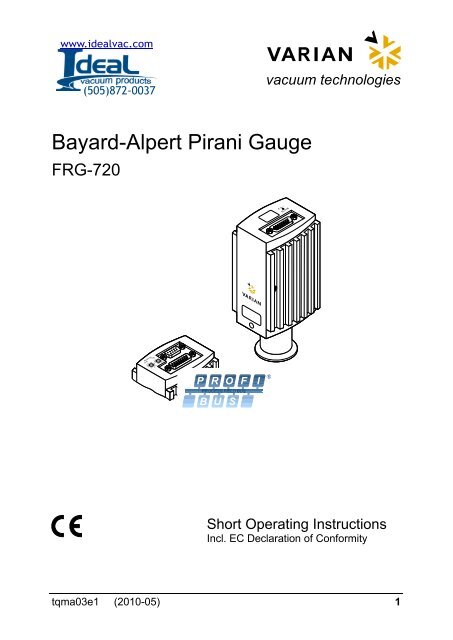
Varain FRG-720 Bayard Alpert Pirani Gauge - Ideal Vacuum Products
Varain FRG-720 Bayard Alpert Pirani Gauge - Ideal Vacuum Products
Varain FRG-720 Bayard Alpert Pirani Gauge - Ideal Vacuum Products
Create successful ePaper yourself
Turn your PDF publications into a flip-book with our unique Google optimized e-Paper software.
www.idealvac.com<br />
(505)872-0037<br />
vacuum technologies<br />
<strong>Bayard</strong>-<strong>Alpert</strong> <strong>Pirani</strong> <strong>Gauge</strong><br />
<strong>FRG</strong>-<strong>720</strong><br />
Short Operating Instructions<br />
Incl. EC Declaration of Conformity<br />
tqma03e1 (2010-05) 1
Product Identification<br />
In all communications with VARIAN, please specify the information<br />
on the product nameplate. For convenient reference copy<br />
that information into the space provided below.<br />
VARIAN Lexington MA 02421 USA<br />
Model:<br />
PN:<br />
SN:<br />
V W<br />
Made in Liechtenstein<br />
Validity<br />
This document applies to products with part numbers<br />
Without display<br />
<strong>FRG</strong><strong>720</strong>KF25 (DN 25 ISO-KF)<br />
<strong>FRG</strong><strong>720</strong>CF35 (DN 40 CF-R)<br />
With display<br />
<strong>FRG</strong><strong>720</strong>KF25D (DN 25 ISO-KF)<br />
<strong>FRG</strong><strong>720</strong>CF35D (DN 40 CF-R)<br />
With Profibus interface and 2 switching functions<br />
<strong>FRG</strong><strong>720</strong>KF25P (DN 25 ISO-KF)<br />
<strong>FRG</strong><strong>720</strong>CF35P (DN 40 CF-R)<br />
The part number (PN) can be taken from the product nameplate.<br />
If not indicated otherwise in the legends, the illustrations in this<br />
document correspond to the gauge with part number<br />
<strong>FRG</strong><strong>720</strong>KF25. They apply to the other gauges by analogy.<br />
2 tqma03e1 (2010-05)
We reserve the right to make technical changes without prior<br />
notice.<br />
All dimensions in mm.<br />
Intended Use<br />
The <strong>FRG</strong>-<strong>720</strong> gauge has been designed for vacuum measurement<br />
of gases in the pressure range of 5×10 -10 … 1000 mbar.<br />
It must not be used for measuring flammable or combustible<br />
gases in mixtures containing oxidants (e.g. atmospheric oxygen)<br />
within the explosion range.<br />
The gauge can be operated in connection with a VARIAN<br />
AGC-100 <strong>Vacuum</strong> <strong>Gauge</strong> Controller, a VARIAN Turbo AG Rack<br />
Controller, or with another controller.<br />
Functional Principle<br />
Standard <strong>Gauge</strong><br />
Over the whole measuring range, the gauge has a continuous<br />
characteristic curve and its measuring signal is output as logarithm<br />
of the pressure.<br />
The gauge functions with a <strong>Bayard</strong>-<strong>Alpert</strong> hot cathode ionization<br />
measurement system (for p < 2.0×10 -2 mbar) and a <strong>Pirani</strong> measurement<br />
system (for p > 5.5×10 -3 mbar). In the overlapping pressure<br />
range of 2.0×10 -2 … 5.5×10 -3 mbar, a mixed signal of the<br />
two measurement systems is output. The hot cathode is<br />
switched on by the <strong>Pirani</strong> measurement system only below the<br />
switching threshold of 2.4×10 -2 mbar (to prevent filament burnout).<br />
It is switched off when the pressure exceeds 3.2×10 -2 mbar.<br />
tqma03e1 (2010-05) 3
Profibus <strong>Gauge</strong><br />
The Profibus gauge has a fieldbus interface that conforms<br />
to the Profibus DPV1 standard (→ [5]). Two<br />
adjustable switching functions are integrated in the<br />
gauges. The corresponding relay contacts are available<br />
at the sensor cable connector.<br />
The basic sensor and sensor electronics of the Profibus<br />
gauge are the same as in the standard <strong>FRG</strong>-<strong>720</strong>.<br />
4 tqma03e1 (2010-05)
Contents<br />
Product Identification 2<br />
Validity 2<br />
Intended Use 3<br />
Functional Principle 3<br />
1 Safety 6<br />
1.1 Symbols Used 6<br />
1.2 Personnel Qualifications 6<br />
1.3 General Safety Instructions 7<br />
1.4 Liability and Warranty 7<br />
2 Technical Data 8<br />
3 Installation 16<br />
3.1 <strong>Vacuum</strong> Connection 16<br />
3.2 Power Connection 19<br />
3.3 Profibus Cable Connection 22<br />
4 Operation 23<br />
4.1 Gas Type Dependence 23<br />
4.2 Display 24<br />
4.3 Profibus Interface 25<br />
4.4 Switching Function Profibus <strong>Gauge</strong> 26<br />
5 Deinstallation 28<br />
6 Maintenance, Repair 30<br />
6.1 Adjustment at Atmospheric Pressure 30<br />
6.2 Zero Point Adjustment 33<br />
7 Returning the Product 34<br />
8 Disposal 35<br />
Further Information 36<br />
EC Declaration of Conformity 37<br />
For cross-references within this document, the symbol (→ XY)<br />
is used, for cross-references to further documents, listed under<br />
further information, the symbol (→ [Z]).<br />
tqma03e1 (2010-05) 5
1 Safety<br />
1.1 Symbols Used<br />
DANGER<br />
Information on preventing any kind of physical injury.<br />
WARNING<br />
Information on preventing extensive equipment and environmental<br />
damage.<br />
Caution<br />
Information on correct handling or use. Disregard can lead to<br />
malfunctions or minor equipment damage.<br />
1.2 Personnel Qualifications<br />
Skilled personnel<br />
All work described in this document may only be carried out by<br />
persons who have suitable technical training and the necessary<br />
experience or who have been instructed by the end-user<br />
of the product.<br />
6 tqma03e1 (2010-05)
1.3 General Safety Instructions<br />
• Adhere to the applicable regulations and take the necessary<br />
precautions for the process media used.<br />
Consider possible reactions between the materials and the<br />
process media.<br />
Consider possible reactions (e.g. explosion) of the process<br />
media due to the heat generated by the product.<br />
• Adhere to the applicable regulations and take the necessary<br />
precautions for all work you are going to do and consider the<br />
safety instructions in this document.<br />
• Before beginning to work, find out whether any vacuum components<br />
are contaminated. Adhere to the relevant regulations<br />
and take the necessary precautions when handling contaminated<br />
parts.<br />
Communicate the safety instructions to all other users.<br />
1.4 Liability and Warranty<br />
VARIAN assumes no liability and the warranty becomes null and<br />
void if the end-user or third parties<br />
• disregard the information in this document<br />
• use the product in a non-conforming manner<br />
• make any kind of interventions (modifications, alterations etc.)<br />
on the product<br />
• use the product with accessories, not listed in the corresponding<br />
product documentation.<br />
The end-user assumes the responsibility in conjunction with the<br />
process media used.<br />
<strong>Gauge</strong> failures due to contamination or wear and tear as well as<br />
expendable parts (filament) are not covered by the warranty.<br />
tqma03e1 (2010-05) 7
2 Technical Data<br />
Measurement<br />
Measurement range<br />
(air, O 2 , CO, N 2 )<br />
Accuracy<br />
(after 5 min. stabilization)<br />
Repeatability<br />
(after 5 min. stabilization)<br />
5×10 -10 … 1000 mbar<br />
continuous<br />
15% of reading in the range<br />
1×10 -8 … 10 -2 mbar<br />
5% of reading in the range<br />
1×10 -8 … 10 -2 mbar<br />
Emission<br />
Switching on threshold<br />
Switching off threshold<br />
Emission current<br />
p ≤7.2×10 -6 mbar<br />
7.2×10 -6 mbar < p<br />
Output signal<br />
Output signal (measuring signal)<br />
Measuring range<br />
Voltage vs. pressure<br />
Error signal (→ [1])<br />
Hot cathode error<br />
<strong>Pirani</strong> error<br />
Minimum loaded impedance<br />
0 … +10 V<br />
+0.774 … +10 V<br />
(5×10 -10 … 1000 mbar)<br />
logarithmic, 0.75 V/decade<br />
≈+0.3 VDC<br />
≈+0.5 VDC<br />
10 kΩ<br />
Identification<br />
<strong>Gauge</strong> identification 42 kΩ between Pin 10 and Pin 5<br />
(sensor cable)<br />
Switching Functions (Profibus gauge only)<br />
Number<br />
Adjustment range<br />
Hysteresis<br />
Relay contact rating<br />
Voltage<br />
Current<br />
2 (setpoints A and B)<br />
1×10 -9 … 100 mbar<br />
adjustable via potentiometers,<br />
one floating, normally open relay<br />
contact per setpoint<br />
10% of the threshold value<br />
≤60 VDC<br />
≤0.5 ADC<br />
RS232C Interface<br />
Data rate<br />
Data format<br />
Connector<br />
Standard gauge<br />
Profibus gauge<br />
9600 Baud<br />
binary, 8 data bits, one stop bit,<br />
no parity bit, no handshake<br />
→ 19<br />
→ 20<br />
Further information on the RS232C interface → [1].<br />
tqma03e1 (2010-05) 9
Profibus Interface<br />
(Profibus gauges only)<br />
Standard applied → [5]<br />
Communication protocol,<br />
Data format → [2], [5]<br />
Interface, physical<br />
RS485<br />
Data rate ≤12 MBaud, → [2], [5]<br />
Node address 00 … 7D hex (0 … 125 dec )<br />
Connection D-Sub, 9-pin, female, → 22<br />
Cable<br />
shielded, special Profibus cable,<br />
→ [3], [5]<br />
Cable length, system<br />
wiring<br />
according to Profibus specifications,<br />
→ [3], [5]<br />
Display (part no. <strong>FRG</strong><strong>720</strong>KF25D and <strong>FRG</strong><strong>720</strong>CF35D only)<br />
Display panel<br />
Dimensions<br />
Pressure unit<br />
Changing the pressure unit<br />
LCD matrix, 32×16 pixels,<br />
with background illumination<br />
16.0 mm × 11.2 mm<br />
mbar (default), Torr, Pa<br />
via RS232C, → [1]<br />
Supply<br />
DANGER<br />
The gauge may only be connected to power supplies,<br />
instruments or control devices that conform<br />
to the requirements of a grounded extra low voltage<br />
(SELV). The connection to the gauge has to be<br />
fused. 1)<br />
1)<br />
VARIAN controllers fulfill these requirements.<br />
10 tqma03e1 (2010-05)
Voltage at the gauge<br />
Power consumption<br />
Standard<br />
Degas<br />
Emission start (200 ms)<br />
Fuse required 1)<br />
Power consumption<br />
Standard gauge<br />
Profibus gauge<br />
+24 VDC (+20 … +28 VDC),<br />
(Ripple ≤2 V pp ) 2)<br />
≤0.5 A<br />
≤0.8 A<br />
≤1.4 A<br />
1.25 AT<br />
≤16 W<br />
≤18 W<br />
Electrical Connection<br />
Connection<br />
Standard gauge<br />
Profibus gauge<br />
Sensor cable<br />
For analog values only,<br />
without degas function<br />
For analog values,<br />
with degas function<br />
All functions,<br />
incl. RS232C interface<br />
Profibus gauge<br />
D-Sub, 15-pin, male<br />
→ 19<br />
→ 20<br />
4 conductors plus shielding<br />
5 conductors plus shielding<br />
7 conductors plus shielding<br />
depending on the functions<br />
used, max. 15 conductors plus<br />
shielding<br />
Cable length (24 VDC) ≤35 m (0.25 mm²/ conductor)<br />
≤50 m (0.34 mm²/ conductor)<br />
≤100 m (1.0 mm²/ conductor)<br />
For RS232C operation ≤30 m<br />
Grounding concept<br />
Standard gauge<br />
Profibus gauge<br />
→ 19<br />
→ 20<br />
2)<br />
Consider the voltage drop as function of the sensor cable length.<br />
tqma03e1 (2010-05) 11
Materials Exposed to <strong>Vacuum</strong><br />
Housing, supports, screens<br />
Feedthroughs<br />
Insulator<br />
Cathode<br />
Cathode holder<br />
<strong>Pirani</strong> element<br />
Internal volume<br />
DN 25 ISO-KF<br />
DN 40 CF-R<br />
Admissible pressure max.<br />
stainless steel<br />
NiFe, nickel plated<br />
glass<br />
iridium, yttrium oxide (Y 2 O 3 )<br />
molybdenum, platinum<br />
tungsten, copper<br />
≈24 cm 3<br />
≈34 cm 3<br />
2 bar (absolute)<br />
Ambient<br />
Admissible temperatures<br />
Storage<br />
Operation<br />
Bakeout<br />
Tube extension<br />
–20 … +70 °C<br />
0 … +50 °C<br />
+80 °C 3)<br />
+150 °C 3)<br />
Relative humidity<br />
Year's mean<br />
During 60 days<br />
Use<br />
Mounting orientation<br />
Degree of protection IP 30<br />
≤65% (no condensation)<br />
≤85% (no condensation)<br />
indoors only<br />
altitude up to 2000 m NN<br />
any<br />
3)<br />
Flange temperature, horizontally mounted, without electronics.<br />
12 tqma03e1 (2010-05)
Dimensions [mm]<br />
4-40UNC 2B<br />
4-40UNC 2B<br />
DN 25 ISO-KF<br />
DN 40 CF-R<br />
Weight<br />
<strong>FRG</strong><strong>720</strong>KF25, <strong>FRG</strong><strong>720</strong>KF25D<br />
<strong>FRG</strong><strong>720</strong>CF35, <strong>FRG</strong><strong>720</strong>CF35D<br />
<strong>FRG</strong><strong>720</strong>KF25P<br />
<strong>FRG</strong><strong>720</strong>CF35P<br />
≈285 g<br />
≈550 g<br />
≈430 g<br />
≈695 g<br />
tqma03e1 (2010-05) 13
Measurement Signal vs. Pressure<br />
Pressure p [mbar]<br />
1E+04<br />
1E+03<br />
1E+02<br />
1E+01<br />
1E+00<br />
1E–01<br />
1E–02<br />
1E–03<br />
1E–04<br />
1E–05<br />
1E–06<br />
sensor error<br />
underrange<br />
overrange<br />
1E–07<br />
1E–08<br />
1E–09<br />
1E–10<br />
0.0<br />
1.0 2.0 3.0 4.0 5.0 6.0 7.0 8.0 9.0 10.0<br />
Measurement signal U [V]<br />
p = 10 (U-7.75)/0.75+c<br />
U p c<br />
[V] [mbar] 0<br />
[V] [Pa] 2<br />
[V] [Torr] -0.125<br />
where p pressure<br />
U measurement signal<br />
c constant (depending on pressure unit)<br />
14 tqma03e1 (2010-05)
Gas Type Dependence<br />
For gases other than air, the pressure reading in the range<br />
p < 10 -3 mbar can be converted by means of the following formula:<br />
p eff = C × pressure reading<br />
Gas<br />
type<br />
He<br />
Ne<br />
Kr<br />
Ar<br />
Calibration<br />
factor C<br />
5.9<br />
4.1<br />
0.5<br />
0.8<br />
Gas type<br />
air, O 2 , CO, N 2<br />
H 2<br />
Xe<br />
Calibration<br />
factor C<br />
1.0<br />
2.4<br />
0.4<br />
tqma03e1 (2010-05) 15
3 Installation<br />
3.1 <strong>Vacuum</strong> Connection<br />
DANGER<br />
DANGER: overpressure in the vacuum system<br />
>1 bar<br />
Injury caused by released parts and harm caused<br />
by escaping process gases can result if clamps are<br />
opened while the vacuum system is pressurized.<br />
Do not open any clamps while the vacuum system<br />
is pressurized. Use the type of clamps which are<br />
suited to overpressure.<br />
DANGER<br />
DANGER: line voltage<br />
<strong>Products</strong> that are not professionally connected to<br />
ground can be extremely hazardous in the event of<br />
a fault.<br />
The gauge must be electrically connected to the<br />
grounded vacuum chamber This connection must<br />
conform to the requirements of a protective connection<br />
according to EN 61010:<br />
• CF connections fulfill this requirement.<br />
• For gauges with KF connection, use a conductive<br />
metallic clamping ring.<br />
16 tqma03e1 (2010-05)
Caution<br />
Caution: vacuum component<br />
Dirt and damages impair the function of the vacuum<br />
component.<br />
When handling vacuum components, take appropriate<br />
measures to ensure cleanliness and prevent<br />
damages.<br />
Caution<br />
Caution: dirt sensitive area<br />
Touching the product or parts thereof with bare<br />
hands increases the desorption rate.<br />
Always wear clean, lint-free gloves and use clean<br />
tools when working in this area.<br />
The gauge may be mounted in any orientation. To keep<br />
condensates and particles from getting into the measuring<br />
chamber preferably choose a horizontal to upright<br />
position.<br />
The gauge is supplied with a built-in grid. For potentially<br />
contaminating applications and to protect the electrodes<br />
against light and fast charged particles, installation of<br />
the optional baffle is recommended (→ [1]).<br />
<strong>Vacuum</strong> connection must be free of grease.<br />
tqma03e1 (2010-05) 17
Remove the protective lid and install the product to the vacuum<br />
system.<br />
Seal with centering ring<br />
Clamp<br />
Keep the<br />
protective lid<br />
18 tqma03e1 (2010-05)
3.2 Power Connection<br />
Make sure the vacuum connection is properly made<br />
(→ 16).<br />
If no sensor cable is available, make one according to the<br />
following diagram.<br />
<strong>FRG</strong>-<strong>720</strong> without Profibus<br />
TxD 13<br />
RxD 14<br />
Measuring 2<br />
signal<br />
12<br />
Degas 7<br />
+Ub<br />
42kΩ<br />
8<br />
5<br />
10<br />
15<br />
1.25AT<br />
+<br />
Identification<br />
RS232C<br />
+ 24 V<br />
–<br />
Electrical connection<br />
Pin 2 Signal output (measuring signal) 0 … +10 V<br />
Pin 5 Supply common, GND<br />
Pin 7 Degas on, active high +24 VDC<br />
Pin 8 Supply +24 VDC<br />
9<br />
1<br />
Pin 10 <strong>Gauge</strong> identification<br />
Pin 12 Signal common, GND<br />
Pin 13 RS232C, TxD<br />
Pin 14 RS232C, RxD<br />
15 8<br />
Pin 15 Shielding, housing, GND<br />
D-Sub, 15-pin<br />
Pins 1, 3, 4, 6, 9 and 11 are<br />
not connected internally.<br />
female,<br />
soldering side<br />
tqma03e1 (2010-05) 19
<strong>FRG</strong>-<strong>720</strong> with Profibus<br />
SP A<br />
SP A<br />
SP B<br />
3<br />
6<br />
1<br />
4<br />
SP B<br />
9<br />
11<br />
TxD<br />
RxD<br />
Degas<br />
+U b<br />
Measuring<br />
signal<br />
42 kΩ<br />
13<br />
14<br />
7<br />
8<br />
2<br />
12<br />
5<br />
10<br />
15<br />
RS232<br />
1.25 AT<br />
Identification<br />
Degas<br />
+ 24 V<br />
–<br />
9<br />
1<br />
15<br />
8<br />
D-Sub, 15-pin female,<br />
soldering side<br />
20 tqma03e1 (2010-05)
Electrical connection<br />
Pin 1 Relay Switching function A, COM contact<br />
Pin 2 Signal output (measuring signal) 0 ... +10 V<br />
Pin 3 Threshold value (Setpoint) A, 0 … +10 V<br />
Pin 4 Relay Switching function A, N.O. contact<br />
Pin 5 Supply common, GND<br />
Pin 6 Threshold value (Setpoint) B, 0 … +10 V<br />
Pin 7 Degas on, active high +24 V<br />
Pin 8 Supply voltage +24 V<br />
Pin 9 Relay Switching function B, COM contact<br />
Pin 10 <strong>Gauge</strong> identification<br />
Pin 11 Relay Switching function B, N.O. contact<br />
Pin 12 Signal common GND<br />
Pin 13 RS232, TxD<br />
Pin 14 RS232, RxD<br />
Pin 15 Shielding, housing GND<br />
Connect the sensor cable to the gauge.<br />
Secure the cable connector with the lock screws and<br />
connect the sensor cable to the controller.<br />
tqma03e1 (2010-05) 21
3.3 Profibus Cable Connection<br />
If no Profibus cable is available, make one according to the<br />
following indications:<br />
1 5<br />
6 9<br />
Pin 1 Do not connect<br />
Pin 2 Do not connect<br />
Pin 3 RxD/TxD-P<br />
Pin 4 CNTR-P 4)<br />
Pin 5 DGND 5)<br />
Pin 6 VP 5)<br />
Pin 7 Do not connect<br />
Pin 8 RxD/TxD-N<br />
Pin 9 Do not connect<br />
D-Sub, 9-pin,<br />
male, soldering side<br />
Connect the Profibus cable to the gauge and secure the<br />
cable socket to the gauge with the lock screws.<br />
4)<br />
5)<br />
Only to be connected if an optical link module is used.<br />
Only required as line termination for devices at the ends of bus system<br />
(→ [5]).<br />
22 tqma03e1 (2010-05)
4 Operation<br />
When the supply voltage is applied, the measurement signal is<br />
available between pins 2 (+) and 12 (–) (relationship between<br />
measurement signal and pressure → 14 and [1]).<br />
The Profibus gauge can also be operated via the corresponding<br />
fieldbus interface (Profibus) (→ [1] for details and further<br />
functions).<br />
Allow for a stabilizing time of ≈10 minutes. Once the gauge has<br />
been switched on, permanently leave it on irrespective of the<br />
pressure.<br />
4.1 Gas Type Dependence<br />
The measurement value is gas type dependent. The pressure<br />
reading applies to dry air, O 2 , CO and N 2 . For other gases, it has<br />
to be converted (→ 15 and [1]).<br />
tqma03e1 (2010-05) 23
4.2 Display<br />
(part no. <strong>FRG</strong><strong>720</strong>KF25D and <strong>FRG</strong><strong>720</strong>CF35D only)<br />
Pressure reading<br />
Pressure unit<br />
Function display<br />
(non) <strong>Pirani</strong> operation<br />
E Emission 25 μA<br />
E . Emission 5 mA<br />
D Degas<br />
A 1000 mbar adjustment<br />
(<strong>Pirani</strong>)<br />
Error Display<br />
ok no error<br />
(green background illumination)<br />
5 <strong>Pirani</strong> sensor warning<br />
(red background illumination)<br />
9 <strong>Pirani</strong> sensor error<br />
(red background illumination)<br />
8 BA sensor error<br />
(red background illumination)<br />
Internal data connection failure<br />
(red background illumination)<br />
24 tqma03e1 (2010-05)
4.3 Profibus Interface<br />
(part no. <strong>FRG</strong><strong>720</strong>KF25P and <strong>FRG</strong><strong>720</strong>CF35P only)<br />
Caution<br />
Caution: data transmission errors<br />
If the gauge is operated with the RS232 and Profibus<br />
interfaces at the same time, data transmission<br />
errors may occur.<br />
The gauge must not be operated with the RS232<br />
and the Profibus interfaces at the same time.<br />
Operating Software<br />
For operating the gauge via Profibus, prior installation of the<br />
gauge specific GSD file is required on the bus master side<br />
(controller, PLC). This file can be downloaded under<br />
www.varianinc.com.<br />
Setting the Device Address "ADDRESS"<br />
The node address (0 … 125 dec ) is set in<br />
hexadecimal form (00 … 7D hex ) via the<br />
"ADDRESS", "MSD", and "LSD" switches. The<br />
node address is polled by the firmware when<br />
the gauge is switched on. If the setting<br />
deviates from the stored value, the new value<br />
is taken over into the NVRAM. If a value<br />
>125 dec (>7D hex ) is entered, the node address<br />
setting currently stored in the device remains<br />
valid but it can now be defined via Profibus<br />
("Set slave Address", → [2]).<br />
The factory setting of the device address is 5C hex .<br />
The device address setting can also be made via Profibus<br />
(→ [2]).<br />
tqma03e1 (2010-05) 25
4.4 Switching Function Profibus <strong>Gauge</strong><br />
The threshold values of switching functions A and B can be set<br />
within the pressure range 1×10 -9 mbar … 100 mbar via<br />
potentiometers "SETPOINT A" and "SETPOINT B". For the<br />
corresponding threshold voltages U Threshold , the following<br />
equation applies:<br />
U Threshold = 0.8129401 × (log p Setpoint – c + 9.30102999)<br />
Constant c depends on the pressure unit (→ 14 and → [1]).<br />
Measuring signal<br />
(Pressure p)<br />
(Setpoint)<br />
Measured value<br />
Hysteresis<br />
10% U Threshold<br />
Time t<br />
U Threshold<br />
Switching<br />
function<br />
Off<br />
On<br />
Off<br />
The hysteresis of the switching functions is 10% of the threshold<br />
setting.<br />
Put the gauge into operation.<br />
Connect the +lead of a voltmeter to the threshold measurement<br />
point of the selected switching function ("Setpoint A"<br />
Pin 3, "Setpoint B" Pin 6) and its –lead to Pin 5.<br />
26 tqma03e1 (2010-05)
Setpoint A Pin 3<br />
Setpoint B Pin 6<br />
Pin 5<br />
max. ø2.5<br />
Using a screwdriver (max. ø2.5 mm), set the threshold of<br />
the selected switching function (Setpoint A, B) to the<br />
desired value U Threshold .<br />
A functional check of the switching functions (On/Off) is only<br />
possible via fieldbus interface (→ [2] for Profibus gauge) or<br />
by measuring the relay contacts with a continuity checker/ohmmeter<br />
(→ "Power Connection", sensor cable connector).<br />
tqma03e1 (2010-05) 27
5 Deinstallation<br />
DANGER<br />
DANGER: contaminated parts<br />
Contaminated parts can be detrimental to health<br />
and environment.<br />
Before beginning to work, find out whether any<br />
parts are contaminated. Adhere to the relevant<br />
regulations and take the necessary precautions<br />
when handling contaminated parts.<br />
Caution<br />
Caution: vacuum component<br />
Dirt and damages impair the function of the vacuum<br />
component.<br />
When handling vacuum components, take appropriate<br />
measures to ensure cleanliness and prevent<br />
damages.<br />
Caution<br />
Caution: dirt sensitive area<br />
Touching the product or parts thereof with bare<br />
hands increases the desorption rate.<br />
Always wear clean, lint-free gloves and use clean<br />
tools when working in this area.<br />
Vent the vacuum system.<br />
Put the gauge out of operation.<br />
28 tqma03e1 (2010-05)
Unfasten the lock screws and unplug the cable socket (and<br />
also the interface cable at Profibus gauge).<br />
Remove the gauge from the vacuum system and put the<br />
protective lid in place.<br />
Protective lid<br />
tqma03e1 (2010-05) 29
6 Maintenance, Repair<br />
In case of severe contamination or a malfunction, the sensor can<br />
be replaced (→ [1]).<br />
<strong>Gauge</strong> failures due to contamination or wear and tear as<br />
well as expendable parts (filaments) are not covered by<br />
the warranty.<br />
6.1 Adjustment at Atmospheric Pressure<br />
The gauge is factory calibrated. If used under different climatic<br />
conditions, at extreme temperatures, through aging or contamination<br />
and after exchanging the sensor, the characteristic<br />
curve can be offset and readjustment can become necessary.<br />
Only the <strong>Pirani</strong> element can be adjusted and only at atmosphere.<br />
Readjustment becomes necessary if<br />
• at atmospheric pressure, the output voltage is
Standard <strong>Gauge</strong><br />
If you are using a seal with centering ring and filter, check<br />
that they are clean or replace them if necessary (→ [1]<br />
"Deinstallation").<br />
Put the gauge into operation.<br />
Operate the gauge for ≈10 minutes at atmospheric<br />
pressure. If the gauge was operated within the BA<br />
range, a cooling-down time of ≈30 minutes is to be<br />
expected (gauge temperature = environmental<br />
temperature).<br />
Adjusting the gauge<br />
<strong>Gauge</strong> without display <strong>Gauge</strong> with display<br />
Insert a pin (≈ø1.3×50mm) through the opening marked<br />
and push the button for at least<br />
5 seconds.<br />
tqma03e1 (2010-05) 31
≈10 s<br />
Automatic adjustment<br />
Adjustment completed<br />
Profibus <strong>Gauge</strong><br />
If you are using a seal with centering ring and filter, check<br />
that they are clean or replace them if necessary (→ [1]<br />
"Deinstallation").<br />
Put the gauge into operation.<br />
Operate the gauge for ≈10 minutes at atmospheric<br />
pressure. If the gauge was operated within the Ioni<br />
range, a cooling-down time of ≈30 minutes is to be<br />
expected (gauge temperature = environmental<br />
temperature).<br />
32 tqma03e1 (2010-05)
Push the button for at least 5 seconds.<br />
max. ø1.3<br />
The gauge is now automatically adjusted. The adjustment<br />
takes ≈4 s.<br />
6.2 Zero Point Adjustment<br />
A zero point adjustment is recommended<br />
• after the sensor has been exchanged<br />
• if display shows "FAIL 5"<br />
• as part of the usual maintenance work for quality assurance<br />
The push button used for the adjustment at atmospheric<br />
pressure is also used for the zero point adjustment<br />
Operate gauge for approx. 10 minutes at a pressure of<br />
≤1×10 -4 mbar.<br />
Push the button for at least 2 seconds.<br />
The adjustment is done automatically and ends after<br />
2 minutes.<br />
tqma03e1 (2010-05) 33
7 Returning the Product<br />
WARNING<br />
WARNING: forwarding contaminated products<br />
Contaminated products (e.g. radioactive, toxic,<br />
caustic or biological hazard) can be detrimental to<br />
health and environment.<br />
<strong>Products</strong> returned to VARIAN should preferably be<br />
free of harmful substances. Adhere to the forwarding<br />
regulations of all involved countries and forwarding<br />
companies and enclose a duly completed<br />
declaration of contamination.<br />
<strong>Products</strong> that are not clearly declared as "free of harmful substances"<br />
are decontaminated at the expense of the customer.<br />
<strong>Products</strong> not accompanied by a duly completed declaration of<br />
contamination are returned to the sender at his own expense.<br />
34 tqma03e1 (2010-05)
8 Disposal<br />
DANGER<br />
DANGER: contaminated parts<br />
Contaminated parts can be detrimental to health<br />
and environment.<br />
Before beginning to work, find out whether any<br />
parts are contaminated. Adhere to the relevant<br />
regulations and take the necessary precautions<br />
when handling contaminated parts.<br />
WARNING<br />
N<br />
WARNING: substances detrimental to the environment<br />
<strong>Products</strong> or parts thereof (mechanical and electric<br />
components, operating fluids etc.) can be detrimental<br />
to the environment.<br />
Dispose of such substances in accordance with the<br />
relevant local regulations.<br />
Separating the Components<br />
After disassembling the product, separate its components according<br />
to the following criteria:<br />
• Contaminated components<br />
Contaminated components (radioactive, toxic, caustic or biological<br />
hazard etc.) must be decontaminated in accordance<br />
with the relevant national regulations, separated according to<br />
their materials, and disposed of.<br />
• Other components<br />
Such components must be separated according to their materials<br />
and recycled.<br />
tqma03e1 (2010-05) 35
Further Information<br />
[1]<br />
[2]<br />
[3]<br />
[4]<br />
[5]<br />
[6]<br />
www.varianinc.com<br />
Instruction Manual<br />
<strong>Bayard</strong>-<strong>Alpert</strong> <strong>Pirani</strong> <strong>Gauge</strong> <strong>FRG</strong>-<strong>720</strong><br />
tqna03e1<br />
Varian <strong>Vacuum</strong> Technologies, Lexington, MA 02421,<br />
USA<br />
www.varianinc.com<br />
Communication Protocol<br />
Profibus <strong>FRG</strong>-<strong>720</strong><br />
tqra33e1<br />
Varian <strong>Vacuum</strong> Technologies, Lexington, MA 02421,<br />
USA<br />
www.profibus.com<br />
Profibus User Organization<br />
www.profibus.com<br />
Profibus Profile Guidelines<br />
Part 1 - Identification & Maintenance Functions<br />
IEC 61158 Type 3 elements: Industrial communication<br />
networks – Fieldbus specifications<br />
IEC 61784: Industrial communication networks –<br />
Fieldbus profiles<br />
www.varianinc.com<br />
Instruction Manual<br />
AGC-100 <strong>Vacuum</strong> <strong>Gauge</strong> Controller<br />
tqnb01e1<br />
Varian <strong>Vacuum</strong> Technologies, Lexington, MA, 02421<br />
USA<br />
36 tqma03e1 (2010-05)
EC Declaration of Conformity<br />
We, VARIAN, hereby declare that the equipment<br />
mentioned below complies with the provisions of<br />
the Directive relating to electromagnetic compatibility<br />
2004/108/EC.<br />
<strong>Products</strong><br />
<strong>Bayard</strong>-<strong>Alpert</strong> <strong>Pirani</strong> <strong>Gauge</strong><br />
<strong>FRG</strong>-<strong>720</strong><br />
Standards<br />
Harmonized and international/national standards and specifications:<br />
• EN 61000-6-2:2005 (EMC: generic immunity standard)<br />
• EN 61000-6-3:2007 (EMC: generic emission standard)<br />
• EN 61010-1:2001 (Safety requirements for electrical equipment for<br />
measurement, control and laboratory use)<br />
• EN 61326:2006 (EMC requirements for electrical equipment for<br />
measurement, control and laboratory use)<br />
Manufacturer / Signature<br />
Varian <strong>Vacuum</strong> Technologies, 121 Hartwell Avenue, Lexington,<br />
MA, 02421 USA<br />
19 May 2010<br />
John Ehmann<br />
General Manager<br />
tqma03e1 (2010-05) 37
Notes<br />
38 tqma03e1 (2010-05)
Notes<br />
tqma03e1 (2010-05) 39
vacuum technologies<br />
121 Hartwell Avenue<br />
Lexington, MA, 02421 USA<br />
Tel: (781) 861 <strong>720</strong>0<br />
Fax: (781) 861 5437<br />
custserv@varianinc.com<br />
t q ma 0 3 e 1 www.varianinc.com


