

Edwards Drystar GV80 Vacuum Pumps - Ideal Vacuum Products
Edwards Drystar GV80 Vacuum Pumps - Ideal Vacuum Products
Edwards Drystar GV80 Vacuum Pumps - Ideal Vacuum Products

Create successful ePaper yourself
Turn your PDF publications into a flip-book with our unique Google optimized e-Paper software.
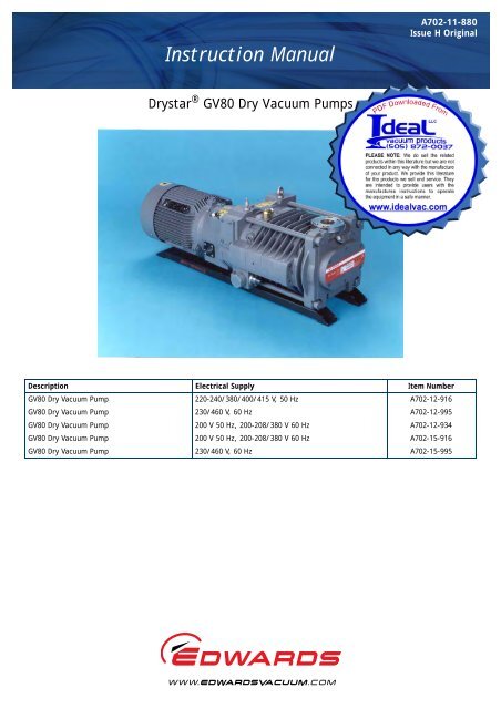
Instruction Manual<br />
A702-11-880<br />
Issue H Original<br />
<strong>Drystar</strong> ® <strong>GV80</strong> Dry <strong>Vacuum</strong> <strong>Pumps</strong><br />
Description Electrical Supply Item Number<br />
<strong>GV80</strong> Dry <strong>Vacuum</strong> Pump 220-240/380/400/415 V, 50 Hz A702-12-916<br />
<strong>GV80</strong> Dry <strong>Vacuum</strong> Pump 230/460 V, 60 Hz A702-12-995<br />
<strong>GV80</strong> Dry <strong>Vacuum</strong> Pump 200 V 50 Hz, 200-208/380 V 60 Hz A702-12-934<br />
<strong>GV80</strong> Dry <strong>Vacuum</strong> Pump 200 V 50 Hz, 200-208/380 V 60 Hz A702-15-916<br />
<strong>GV80</strong> Dry <strong>Vacuum</strong> Pump 230/460 V, 60 Hz A702-15-995
P900-77-000IssueA
A702-11-880 Issue H<br />
Contents<br />
Section<br />
Page<br />
1 Introduction ....................................................................................... 1<br />
Contents<br />
1.1 Scope and definitions ................................................................................................... 1<br />
1.2 The GV pumps ............................................................................................................ 1<br />
1.3 Gas system ................................................................................................................ 2<br />
1.4 Cooling system ........................................................................................................... 4<br />
1.5 Motor over-temperature protection .................................................................................. 4<br />
1.6 Liquid pumping capability .............................................................................................. 4<br />
1.7 Safe area operation ..................................................................................................... 4<br />
1.8 Accessories ................................................................................................................ 4<br />
2 Technical data .................................................................................... 5<br />
2.1 General .................................................................................................................... 5<br />
2.2 Materials of construction ............................................................................................... 5<br />
2.3 Services .................................................................................................................... 8<br />
2.4 Cooling system ........................................................................................................... 9<br />
2.5 Lubrication system ...................................................................................................... 9<br />
2.5.1 Gearbox ................................................................................................................... 9<br />
2.5.2 High vacuum bearings ................................................................................................... 9<br />
2.6 Area classification in accordance with BS 5345 ..................................................................... 9<br />
3 Installation ....................................................................................... 11<br />
3.1 Safety .....................................................................................................................11<br />
3.2 Unpack and inspect .....................................................................................................11<br />
3.3 Locate the pump ........................................................................................................12<br />
3.4 Check the gearbox oil-level ...........................................................................................12<br />
3.5 Electrical connections ..................................................................................................12<br />
3.5.1 Introduction ............................................................................................................. 14<br />
3.5.2 Connect to the pump-motor terminal-box ..........................................................................14<br />
3.5.3 Connect to the thermal snap-switches ..............................................................................15<br />
3.6 Check the direction of pump rotation ...............................................................................17<br />
3.7 Fit a mechanical booster pump (optional) ..........................................................................17<br />
3.8 Connect the cooling-water supply ...................................................................................17<br />
3.9 Connect the shaft-seals purge and gas-ballast gas supplies ......................................................18<br />
3.9.1 Introduction ............................................................................................................. 18<br />
3.9.2 Connect the shaft-seals purge air or nitrogen supply .............................................................18<br />
3.9.3 Connect a nitrogen gas-ballast supply (optional) ..................................................................19<br />
3.10 Connect the pump-inlet and pump-outlet ..........................................................................20<br />
3.10.1 Connect the pump to your process system .........................................................................20<br />
3.10.2 Connect the pump-outlet ..............................................................................................21<br />
3.11 Leak test the installation ..............................................................................................21<br />
3.12 Commission the pump ..................................................................................................22<br />
4 Operation ........................................................................................ 23<br />
4.1 Start the pump ..........................................................................................................23<br />
4.2 Check the purge pressures and flows ................................................................................24<br />
4.3 Shut down the pump ...................................................................................................24<br />
5 Maintenance ..................................................................................... 25<br />
dcs/8268/0209<br />
5.1 Safety .....................................................................................................................25<br />
5.2 Maintenance plan .......................................................................................................25<br />
© <strong>Edwards</strong> Limited 2009. All rights reserved. Page i<br />
<strong>Edwards</strong> and the <strong>Edwards</strong> logo are trademarks of <strong>Edwards</strong> Limited.
A702-11-880 Issue H<br />
Contents<br />
5.3 Check the gearbox oil-level and fill the gearbox with oil (if necessary) .......................................26<br />
5.4 Inspect the gas-ballast system ........................................................................................27<br />
5.5 Inspect the pipelines and connections ..............................................................................27<br />
5.6 Change the gearbox oil and clean the oil-level sight-glass .......................................................29<br />
5.7 Relubricate the high vacuum bearings ..............................................................................30<br />
5.8 Flush the cooling jacket ...............................................................................................32<br />
5.9 Replace the gas ballast filter .........................................................................................32<br />
5.10 Replace the pump-motor bearings ...................................................................................33<br />
5.11 Overhaul the pump .....................................................................................................33<br />
5.12 Fault finding ............................................................................................................. 34<br />
6 Storage and disposal ........................................................................... 35<br />
6.1 Storage ...................................................................................................................35<br />
6.2 Disposal ................................................................................................................... 35<br />
7 Service, spares and accessories .............................................................. 37<br />
7.1 Introduction .............................................................................................................37<br />
7.2 Service .................................................................................................................... 37<br />
7.3 Spares and maintenance kits ..........................................................................................37<br />
7.4 Accessories ...............................................................................................................37<br />
7.4.1 Exhaust silencer ......................................................................................................... 37<br />
7.4.2 Booster connection kit .................................................................................................38<br />
7.4.3 Indirect cooling kit .....................................................................................................38<br />
7.4.4 Acoustic enclosure ......................................................................................................38<br />
7.4.5 Other accessories .......................................................................................................38<br />
Appendix A1<br />
Correct use of Swagelok<br />
connectors ................................................................................ 39<br />
A1.1 Fit a Swagelok connector ..............................................................................................39<br />
A1.2 Reconnect a Swagelok connector ....................................................................................39<br />
For return of equipment, complete the HS Forms at the end of this manual.<br />
Illustrations<br />
Figure<br />
Page<br />
1 The GV pump: key ....................................................................................................... 2<br />
2 Dimensions ................................................................................................................ 7<br />
3 Schematic diagram of the recommended electrical connections ...............................................13<br />
4 Connect to the thermal snap-switches ..............................................................................16<br />
5 Oil-level sight-glass and oil filler port ...............................................................................28<br />
6 Relubricate the high vacuum bearings ..............................................................................31<br />
A1 Fit a Swagelok fitting ..................................................................................................40<br />
A2 Retighten a Swagelok fitting ..........................................................................................41<br />
Page ii<br />
© <strong>Edwards</strong> Limited 2009. All rights reserved.<br />
<strong>Edwards</strong> and the <strong>Edwards</strong> logo are trademarks of <strong>Edwards</strong> Limited.
A702-11-880 Issue H<br />
Tables<br />
Table<br />
Page<br />
1 Technical data: 220-240/380/400/415 V, 50 Hz electrical supplies ............................................. 6<br />
2 Technical data: 230/460 V, 60 Hz electrical supplies .............................................................. 6<br />
3 Electrical data ............................................................................................................ 8<br />
4 Checklist of components ...............................................................................................12<br />
5 Maintenance plan .......................................................................................................26<br />
6 Fault finding .............................................................................................................34<br />
Contents<br />
Associated publications<br />
Publication title<br />
<strong>Vacuum</strong> pump and vacuum system safety<br />
Publication number<br />
P300-20-000<br />
© <strong>Edwards</strong> Limited 2009. All rights reserved. Page iii<br />
<strong>Edwards</strong> and the <strong>Edwards</strong> logo are trademarks of <strong>Edwards</strong> Limited.
A702-11-880 Issue H<br />
This page has been intentionally left blank.<br />
Page iv<br />
© <strong>Edwards</strong> Limited 2009. All rights reserved.<br />
<strong>Edwards</strong> and the <strong>Edwards</strong> logo are trademarks of <strong>Edwards</strong> Limited.
A702-11-880 Issue H<br />
1 Introduction<br />
1.1 Scope and definitions<br />
This manual provides installation, operation and maintenance instructions for the <strong>Edwards</strong> <strong>GV80</strong> Dry <strong>Vacuum</strong> Pump<br />
(abbreviated to GV pump in the remainder of this manual). You must use the GV pump as specified in the manual.<br />
Read this manual before you install and operate the GV pump. Important safety information is highlighted as<br />
WARNING and CAUTION instructions; you must obey these instructions. The use of WARNINGS and CAUTIONS is defined<br />
below.<br />
Introduction<br />
WARNING<br />
Warnings are given where failure to observe the instruction could result in injury or death to<br />
people.<br />
CAUTION<br />
Cautions are given where failure to observe the instruction could result in damage to the equipment, associated<br />
equipment and process<br />
The following IEC warning labels appear on the pump:<br />
Warning - refer to accompanying documentation.<br />
Warning - risk of electric shock.<br />
Warning - hot surface.<br />
The units used throughout this manual conform to the SI international system of units of measurement.<br />
Note:<br />
Refer to Figure 1 in the descriptions in the following sections.<br />
1.2 The GV pumps<br />
The GV pumps are rugged, reliable dry vacuum pumps designed for general vacuum use<br />
The pump is a three-stage, positive displacement rotary pump in which pairs of intermeshing rotors (mounted on<br />
common shafts) are held in correct phase relation by a pair of timing-gears. The timing-gears and the adjacent<br />
double-row angular contact ball bearings are oil lubricated.<br />
The pump has lifting-bolts (1) and is mounted on a robust frame (9). Fixing holes (10) in the frame can be used to<br />
secure the pump frame in its operating position.<br />
© <strong>Edwards</strong> Limited 2009. All rights reserved. Page 1<br />
<strong>Edwards</strong> and the <strong>Edwards</strong> logo are trademarks of <strong>Edwards</strong> Limited.
A702-11-880 Issue H<br />
Introduction<br />
1.3 Gas system<br />
The pump has a shaft-seals purge system and a gas-ballast system.<br />
You can connect a dry compressed air supply to the shaft-seals purge inlet (18). The shaft-seals purge pipeline then<br />
delivers the dry air purge to the shaft-seals. This dry air purge: ensures that the shaft-seals are maintained at a<br />
positive pressure during pump operation; prevents the entry of corrosive or toxic process vapours into the pump<br />
gearbox; prevents contamination of the process gases by pump oil; prevents damage to the shaft-seals by debris.<br />
As supplied, the gas-ballast system can deliver ambient air to the pump gas-ballast inlet. The air-flow is filtered and<br />
is controlled by a valve (13). A check-valve in the system prevents the escape of process gases out of the gas-ballast<br />
system into the local atmosphere.<br />
If required for your application, you can connect dry nitrogen supplies to the pump, to deliver nitrogen gas-ballast<br />
and nitrogen shaft-seals purge instead of air: refer to Section 3.9.<br />
Figure 1 - The GV pump: key<br />
1. Lifting-bolts<br />
2. Pump-motor<br />
3. Direction of rotation arrow<br />
4. Cooling-fan<br />
5. Terminal-box<br />
6. Pump-outlet<br />
7. Temperature measurement point<br />
8. Thermal snap-switch box<br />
9. Pump frame<br />
10. Fixing hole<br />
11. Pump-inlet<br />
12. Cooling-water outlet<br />
13. Gas-ballast flow valve<br />
14. Gas-ballast inlet<br />
15. Air filter<br />
16. Oil-level sight-glass<br />
17. Cooling-water inlet<br />
18. Shaft-seals purge inlet<br />
19. Outlet-flange O-ring<br />
20. Air bleed plug<br />
21. TCV probe port<br />
Page 2<br />
© <strong>Edwards</strong> Limited 2009. All rights reserved.<br />
<strong>Edwards</strong> and the <strong>Edwards</strong> logo are trademarks of <strong>Edwards</strong> Limited.
A702-11-880 Issue H<br />
Figure 1 - The GV pump<br />
Introduction<br />
© <strong>Edwards</strong> Limited 2009. All rights reserved. Page 3<br />
<strong>Edwards</strong> and the <strong>Edwards</strong> logo are trademarks of <strong>Edwards</strong> Limited.
A702-11-880 Issue H<br />
Introduction<br />
1.4 Cooling system<br />
Note:<br />
The direct cooling system fitted to the pump is suitable for pump operating temperatures (measured at the<br />
position shown in Figure 1, item 7) of up to 45 °C, (113 °F). If your application requires pump operating<br />
temperatures of 45 to 90 °C (113 to 194 °F), we recommend that you fit an Indirect Cooling Kit accessory:<br />
refer to Section 7.4.3.<br />
The pump has a direct cooling system, in which cooling-water (connected through the cooling- water inlet, 17)<br />
circulates around the pump-body and then passes out of the pump through the cooling-water outlet (12). The pumpmotor<br />
(2) is air-cooled by an integral cooling-fan (4).<br />
The thermal snap-switch box (8) on the pump-body has two thermal snap-switches:<br />
• The output of the warning thermal snap-switch will go open circuit when the temperature of the pump-body<br />
is higher than normal. Use this output to provide a warning of high pump temperature.<br />
• The output of the shut-down thermal snap-switch will go open circuit when the temperature of the pumpbody<br />
is too high. Use this output to shut-down the pump when it is too hot.<br />
1.5 Motor over-temperature protection<br />
A motor-protection thermistor is fitted to the pump-motor. This thermistor is a solid-state device which has a low<br />
electrical resistance at normal pump-motor operational temperature. When the pump-motor is too hot, the electrical<br />
resistance of the thermistor rises quickly. You can connect the outputs of the thermistor to your control equipment<br />
to shut down the pump if the pump-motor is too hot.<br />
1.6 Liquid pumping capability<br />
The GV pump cannot survive the ingress of liquid (after a process failure condition, for example) without damage. If<br />
you want to pump liquids, contact your supplier or <strong>Edwards</strong> for advice.<br />
1.7 Safe area operation<br />
You must not use the GV pump in the following hazardous areas:<br />
• Zone 0, Zone 1 or Zone 2 (gases), or Zone Z (10) or Zone Y (11) (dusts), as classified by European authorities.<br />
• Division 1 or Division 2 (gases and dusts), as classified by North American authorities.<br />
These hazardous areas require the use of flameproof equipment. If you need a pump which can operate in these<br />
areas, contact your supplier or <strong>Edwards</strong> for advice.<br />
1.8 Accessories<br />
A number of accessories are available for the GV pumps; use these to configure the pump for specific applications.<br />
These accessories are listed in Section 7.<br />
Page 4<br />
© <strong>Edwards</strong> Limited 2009. All rights reserved.<br />
<strong>Edwards</strong> and the <strong>Edwards</strong> logo are trademarks of <strong>Edwards</strong> Limited.
A702-11-880 Issue H<br />
2 Technical data<br />
2.1 General<br />
Dimensions See Figure 2<br />
Mass See Tables 1 and 2<br />
Pump-motor rating See Tables 1 and 2<br />
Full load and no-load current ratings See Table 3<br />
Typical pump rotation speed<br />
50 Hz electrical supply 3000 rev.min -1<br />
60 Hz electrical supply 3600 rev.min -1<br />
Warm-up time to pump operating temperature<br />
of 40°C (104°F), with a cooling-water flow rate<br />
of 150 l.h -1 (33 US gallons.h -1 )<br />
15 min<br />
Pump-inlet connection<br />
ISO40<br />
Pump-outlet connection<br />
NW40<br />
Recommended pump-inlet seal<br />
Fluoroelastomer trapped O-ring<br />
Recommended pump-outlet seal<br />
Fluoroelastomer trapped O-ring<br />
Ambient operating temperature range 0 to 40°C, 32 to 104°F<br />
Maximum ambient operating humidity<br />
100% RH<br />
Maximum outlet pressure<br />
1.3 bar absolute, 1.3 x 10 5 Pa, 975 torr<br />
Swept volume maximum pressure rating<br />
11 bar absolute, 1.1 x 10 6 Pa, 8250 torr<br />
Typical continuous A-weighted sound pressure level See Tables 1 and 2<br />
Performance See Tables 1 and 2<br />
Technical data<br />
2.2 Materials of construction<br />
Rotors Grey cast iron, grade 250<br />
Stators Grey cast iron, grade 250<br />
Shafts<br />
Carbon steel 817 M40<br />
Sleeves<br />
Stainless steel 431 S29<br />
Bearing holders<br />
Stainless steel 410 C21<br />
Inlet flange<br />
Carbon steel<br />
Outlet flange Grey cast iron, grade 250<br />
Gearbox Grey cast iron, grade 250<br />
Coupling cover Grey cast iron, grade 250<br />
O-rings<br />
Fluoroelastomer<br />
Shaft seals<br />
Carbon filled PTFE (polytetrafluoroethylene)<br />
Timing gears<br />
Carbon steel 817 M40<br />
© <strong>Edwards</strong> Limited 2009. All rights reserved. Page 5<br />
<strong>Edwards</strong> and the <strong>Edwards</strong> logo are trademarks of <strong>Edwards</strong> Limited.
A702-11-880 Issue H<br />
Technical data<br />
Table 1 - Technical data: 220-240/380/400/415 V, 50 Hz electrical supplies<br />
Mass (without oil)<br />
145 kg<br />
Pump-motor rating<br />
5.75 kW<br />
Typical continuous A-weighted sound pressure level < 78 dB (A)<br />
Maximum pumping speed 82 m3h -1<br />
Displacement (swept volume) 91.5 m 3 h -1<br />
Ultimate vacuum<br />
3 x 10 -2 mbar<br />
3 Pa<br />
Typical heat removed from pump by cooling-water 1.1 kW<br />
Maximum water consumption * 1 l.min -1<br />
* Pump at typical operating temperature of 44°C, at ultimate vacuum with a cooling-water supply<br />
temperature of 28°C and an ambient temperature of 20°C.<br />
Table 2 - Technical data: 230/460 V, 60 Hz electrical supplies<br />
Mass (without oil)<br />
320 lb<br />
Pump-motor rating<br />
8 h.p.<br />
Typical continuous A-weighted sound pressure level < 80 dB (A)<br />
Maximum pumping speed<br />
64.6 cfm<br />
Displacement (swept volume)<br />
53.8 cfm<br />
Ultimate vacuum<br />
2.25 x 10 -2 torr<br />
Typical heat removed from pump by cooling-water 3412 btu<br />
Maximum water consumption * 17.5 US gallons.h -1<br />
* Pump at typical operating temperature of 111°F, at ultimate vacuum with a cooling-water supply<br />
temperature of 82°F and an ambient temperature of 68°F.<br />
Page 6<br />
© <strong>Edwards</strong> Limited 2009. All rights reserved.<br />
<strong>Edwards</strong> and the <strong>Edwards</strong> logo are trademarks of <strong>Edwards</strong> Limited.
A702-11-880 Issue H<br />
Figure 2 - Dimensions<br />
Technical data<br />
A Top view 1. Pump-inlet<br />
B Side view 2. Fixing holes: ∅9 mm, 0.35 inches<br />
3. Pump-outlet<br />
Electrical Supply Units A B C D E F G H J<br />
50 Hz mm 737 270 301 80 160 67 275 156 143<br />
60 Hz inches 29 10.63 11.85 3.15 6.30 2.64 10.83 6.14 5.63<br />
© <strong>Edwards</strong> Limited 2009. All rights reserved. Page 7<br />
<strong>Edwards</strong> and the <strong>Edwards</strong> logo are trademarks of <strong>Edwards</strong> Limited.
A702-11-880 Issue H<br />
Technical data<br />
2.3 Services<br />
.<br />
Electrical supply<br />
Cooling-water supply<br />
Supply temperature range 5 to 35°C, 41 to 95°F<br />
Maximum supply pressure<br />
Minimum required pressure differential across<br />
supply and return<br />
See motor rating plate for voltage and wiring details<br />
8 bar absolute, 8 x 10 5 Pa, 116 psi, 5.99 x 10 3 torr<br />
2.1 bar absolute, 2.1 x 10 5 Pa, 30 psi,<br />
1.55 x 10 3 torr<br />
Typical heat removed from pump See Tables 1 and 2<br />
Maximum water consumption See Tables 1 and 2<br />
Maximum particle size in supply 0.03 mm 2 , 4.65 x 10 -5 inch 2<br />
Fittings type, suitable for<br />
1/2 inch outside diameter rigid tube<br />
Shaft-seals purge nitrogen supply<br />
Minimum supply pressure<br />
0.3 bar gauge, 1.3 bar absolute, 4.35 psi gauge, 1.3 x<br />
10 5 Pa, 9.75 x 10² torr<br />
Maximum supply pressure<br />
0.8 bar gauge, 1.8 bar absolute, 11.6 psi gauge, 1.8 x<br />
10 5 Pa, 1.35 x 10 3 torr<br />
Maximum flow rate 25 l.min -1 , 0.88 ft 3 min -1<br />
Fittings type, suitable for<br />
1/4 inch outside diameter rigid tube<br />
Electrical supply<br />
Table 3 - Electrical data<br />
Power (kW)<br />
220-240 V, 50 Hz 4.00<br />
380/400/415 V, 50 Hz 4.00<br />
230 V, 60 Hz 5.75 *<br />
460 V, 60 Hz 5.75*<br />
* In normal operating conditions, this power is consumed for 15 minutes only, during rough pumping.<br />
Continuous pump operation with high inlet pressure will cause the pump-motor to overheat; if you have<br />
connected the motor-protection thermistor to your control equipment as described in Section 3.5.1, the<br />
pump will be automatically shut-down when the pump-motor is too hot.<br />
Page 8<br />
© <strong>Edwards</strong> Limited 2009. All rights reserved.<br />
<strong>Edwards</strong> and the <strong>Edwards</strong> logo are trademarks of <strong>Edwards</strong> Limited.
A702-11-880 Issue H<br />
2.4 Cooling system<br />
Cooling system type<br />
Direct water-cooling<br />
Cooling-water requirements See Section 2.3 and Tables 1 and 2<br />
Thermal snap-switches<br />
Warning thermal snap-switch<br />
Opening temperature 88°C, 190°F<br />
Closing temperature 78°C, 172°F<br />
Shut-down thermal snap-switch<br />
Opening temperature 95°C, 203°F<br />
Closing temperature 85°C, 185°F<br />
Contact ratings<br />
Maximum voltage<br />
60 V d.c., 25 V a.c.<br />
Maximum current (inductive load) *<br />
0.2 A (d.c. voltage), 1 A (a.c. voltage)<br />
* Protective extra low voltage.<br />
Technical data<br />
2.5 Lubrication system<br />
Note:<br />
<strong>Edwards</strong> Material Safety Data Sheets for the recommended oil and grease referenced in the sections below<br />
are available on request.<br />
2.5.1 Gearbox<br />
Gearbox oil capacity<br />
Recommended oil *<br />
0.4 litres, 0.1 US gallons<br />
Mobil SHC 629 Antiwear Synthetic Gear Oil 150 cst<br />
* The pump is supplied filled with this oil. Pump operating temperature is measured at the point shown in<br />
Figure 1, item 7. For pump operating temperatures higher than 45°C (113°F), we recommend that you fit<br />
an Indirect Cooling Kit: refer to Section 7.4.3.<br />
Note:<br />
In the PFPE versions the oil is:<br />
Recommended PFPE oil Fomblin 25/6<br />
2.5.2 High vacuum bearings<br />
Grease type<br />
Recommended grease<br />
Perfluoropolyether<br />
Fomblin RT15<br />
2.6 Area classification in accordance with BS 5345<br />
Standard pumps<br />
Safe Area designation only<br />
© <strong>Edwards</strong> Limited 2009. All rights reserved. Page 9<br />
<strong>Edwards</strong> and the <strong>Edwards</strong> logo are trademarks of <strong>Edwards</strong> Limited.
A702-11-880 Issue H<br />
This page has been intentionally left blank.<br />
Page 10<br />
© <strong>Edwards</strong> Limited 2009. All rights reserved.<br />
<strong>Edwards</strong> and the <strong>Edwards</strong> logo are trademarks of <strong>Edwards</strong> Limited.
A702-11-880 Issue H<br />
3 Installation<br />
3.1 Safety<br />
WARNING<br />
Obey the safety instructions given below and take note of appropriate precautions. If you do not,<br />
you can cause injury to people and damage to equipment.<br />
Installation<br />
• A suitably trained and supervised technician must install your GV pump.<br />
• Ensure that you comply with all local and national safety requirements when you install the pump. In the US,<br />
make the wiring connections to the pump-motor in accordance with the US National Electrical Code.<br />
• Ensure that the installation technician is familiar with the safety procedures which relate to the products<br />
pumped. Wear the appropriate safety-clothing when you come into contact with contaminated components.<br />
Dismantle and clean contaminated components inside a fume-cupboard.<br />
• Vent and purge the process system before you start installation work.<br />
• Check that all the required components are available and of the correct type before you start.<br />
• Disconnect the other components in the process system from the electrical supply so that they cannot be<br />
operated accidentally.<br />
• Do not reuse O-rings if they are damaged.<br />
• Ensure that you connect, disconnect and tighten Swagelok connectors correctly: refer to Appendix A1.<br />
3.2 Unpack and inspect<br />
WARNING<br />
Use suitable lifting-equipment to move the pump. Refer to Section 2 for the pump mass.<br />
1. Use a fork-lift truck or a pallet truck to place the pallet in a convenient position.<br />
2. Remove the cardboard sleeve which covers the pump, then remove the protective foil bag from around the<br />
pump.<br />
3. Inspect the equipment. If the pump or any of the other items is damaged, notify your supplier and the carrier in<br />
writing within three days; state the Item Number of the pump together with your order number and your<br />
supplier’s invoice number. Retain all packing materials for inspection. Do not use the pump if it is damaged.<br />
4. Check that you have received the items listed in Table 4. If any of these items is missing, notify your supplier in<br />
writing within three days.<br />
5. If the pump is not to be used immediately, replace the packing materials. Store the pump in suitable conditions<br />
as described in Section 6.<br />
© <strong>Edwards</strong> Limited 2009. All rights reserved. Page 11<br />
<strong>Edwards</strong> and the <strong>Edwards</strong> logo are trademarks of <strong>Edwards</strong> Limited.
A702-11-880 Issue H<br />
Installation<br />
Table 4 - Checklist of components<br />
Qty Description Check ()<br />
1 GV pump <br />
Fittings kit, which contains:<br />
1 Swagelok nut: 1/2 inch <br />
1 Swagelok ferrule: 1/2 inch <br />
1 Swagelok nut: 1/4 inch <br />
1 Swagelok ferrule: 1/4 inch <br />
1 NW40 clamping ring <br />
1 NW40 trapped O-ring <br />
3.3 Locate the pump<br />
WARNING<br />
Use suitable lifting-equipment to move the pump. Refer to Section 2 for the mass of the pump.<br />
Note:<br />
If you want to operate the pump in an environment with an ambient temperature of 0°C (32°F) or lower,<br />
contact your supplier or <strong>Edwards</strong> for advice.<br />
Ensure that the cooling-air flow around the pump-motor is not restricted.<br />
1. Refer to Figure 1. Remove from the fixing-holes (10) the four nuts and bolts which secure the pump frame (9) to<br />
the pallet.<br />
2. Attach suitable lifting-equipment to the two lifting bolts (1) to move the pump.<br />
3. Locate the pump on a firm, level surface. Ensure that the surface is clean and free from debris and<br />
contamination (such as oil). Use suitable bolts through the four fixing-holes (10) to secure the pump in position.<br />
3.4 Check the gearbox oil-level<br />
Refer to Figure 1. The pump is supplied filled with oil. Before you operate the pump, check that the gearbox oil-level<br />
is correct: the oil-level must be between the MIN and MAX marks on the bezel of the oil-level sight-glass (16): see<br />
detail B. If necessary, pour more oil into the gearbox: refer to Section 5.3.<br />
3.5 Electrical connections<br />
WARNING<br />
Ensure that the electrical installation of your pump conforms with your local and national safety<br />
requirements. The pump must be connected to a suitably fused and protected electrical supply<br />
and a suitable earth (ground) point.<br />
Page 12<br />
© <strong>Edwards</strong> Limited 2009. All rights reserved.<br />
<strong>Edwards</strong> and the <strong>Edwards</strong> logo are trademarks of <strong>Edwards</strong> Limited.
A702-11-880 Issue H<br />
Figure 3 - Schematic diagram of the recommended electrical connections<br />
Installation<br />
1. To your electrical supply<br />
2. Earth (ground) points<br />
3. Auxiliary contacts (2 off, normally closed)<br />
4. Fuse or circuit breaker<br />
5. Contactor K1 contacts<br />
6. Stop control<br />
7. Start control<br />
8. Shut-down thermal snap-switch<br />
9. Pump-motor thermistor contacts<br />
10. Contactor K1 drive coil<br />
11. Control voltage<br />
12. Inlet-valve control solenoid (optional)<br />
A. Pump-motor connections<br />
B. Control circuit<br />
Earth (ground) points<br />
Location<br />
Size<br />
Thermal snap-switch box M4 tapped hole<br />
*<br />
Pump-motor<br />
* Refer to the pump-motor terminal-box.<br />
© <strong>Edwards</strong> Limited 2009. All rights reserved. Page 13<br />
<strong>Edwards</strong> and the <strong>Edwards</strong> logo are trademarks of <strong>Edwards</strong> Limited.
A702-11-880 Issue H<br />
Installation<br />
3.5.1 Introduction<br />
We recommend that you connect the electrical supply to the pump through a suitable starter or circuit breaker which<br />
has thermal over-current protection and a thermistor control module which complies with IEC34-11 or BS4999 Part<br />
III. You must adjust the over-current protection to suit your installation.<br />
The pump will restart automatically when the electrical supply is restored after it has been interrupted. If you do<br />
not want the pump to automatically restart, connect the electrical suppy to the pump-motor through control<br />
equipment which must be manually reset after an electrical supply interruption.<br />
Refer to Figure 1. Note that there are earth (ground) points in the pump-motor terminal-box (5) and in the thermal<br />
snap-switch box (8).<br />
3.5.2 Connect to the pump-motor terminal-box<br />
CAUTION<br />
Ensure that the pump-motor terminal box is correctly configured for your electrical supply. If the terminal-box<br />
is not correctly configured, you can damage the pump-motor when you operate it.<br />
The bottom of the pump-motor terminal-box has a number of cable-entry leadthrough holes, sealed by plugs; you<br />
can connect to the terminal-box in one of two ways:<br />
• You can use a single 6-core cable to connect the electrical supply to the pump-motor terminals and to<br />
connect the outputs of the motor protection thermistor to your control equipment. If you use this option,<br />
remove the plug from one of the cable-entry leadthrough holes.<br />
• You can use a 4-core cable to connect the electrical supply to the pump-motor terminals, and use a 2-core<br />
cable to connect the outputs of the motor protection thermistor to your control equipment. If you use this<br />
option, remove the plugs from two of the cable-entry leadthrough holes.<br />
Use the following procedure to make the electrical connections to the pump-motor terminal box:<br />
1. Remove the cover from the pump-motor terminal-box (Figure 1, item 5).<br />
2. Remove the plug (s) from the cable-entry leadthrough hole(s) that you intend to use from the bottom of the<br />
terminal-box.<br />
3. Fit suitable cable-gland (s) and nut(s) to the entry hole (s), then pass the cable (s) through the cable-gland (s)<br />
and tighten the cable-gland (s). The cable-gland (s) you use must be rated to provide seal protection of IP55 (in<br />
IEC 529) or better to the terminal-box.<br />
4. Ensure that the terminal-box is correctly configured for your electrical supply voltage, as indicated by the motor<br />
suppliers information. This will be on the rating plate or in the terminal box.<br />
5. Connect the earth (ground) wire in your cable to the earth (ground) terminal (4).<br />
6. Connect the other ends of the phase conductors and the earth (ground) wire to your electrical supply.<br />
7. Connect the two thermistor wires in your cable to the terminals on the thermistor block.<br />
8. Connect the other end of the thermistor wires to your control equipment.<br />
9. Tighten the cable-gland nut (s) strain-relief screws and refit the terminal-box cover.<br />
Page 14<br />
© <strong>Edwards</strong> Limited 2009. All rights reserved.<br />
<strong>Edwards</strong> and the <strong>Edwards</strong> logo are trademarks of <strong>Edwards</strong> Limited.
A702-11-880 Issue H<br />
3.5.3 Connect to the thermal snap-switches<br />
WARNING<br />
You must connect the shut-down thermal snap-switch so that the pump stops when the thermal<br />
snap-switch opens. If you do not, there may be a risk of fire or explosion.<br />
WARNING<br />
Installation<br />
Incorporate a manual reset device in your control equipment. If you do not (and a fault which<br />
causes the shut-down thermal snap-switch to open is not corrected), the pump will automatically<br />
switch on again when it cools down. If you have started maintenance or fault finding on the pump,<br />
there will then be a risk of fire or explosion and injury to people.<br />
CAUTION<br />
Ensure that you route the thermal snap-switch cable away from hot surfaces of the pump or other equipment.<br />
If you do not, the cable may be damaged.<br />
Connect the output of the warning thermal snap-switch to your control equipment to provide an indication that the<br />
pump is too hot.<br />
You must connect the output of the shut-down thermal snap-switch to the electrical-overload control-loop of your<br />
contactor, so that the contactor will automatically switch off the pump if it is too hot: refer to Figure 3.<br />
The thermal snap-switches will reset (that is, close again) when the pump cools down to a preset temperature (see<br />
Section 2). You must therefore ensure that your control equipment incorporates a manual reset device so that the<br />
pump does not automatically switch on again when it cools down.<br />
Use the following procedure to connect to the thermal snap-switches. If you connect to the thermal snap-switches<br />
as described below, the outputs from the thermal snap-switches will be normally closed and will open when the pump<br />
is too hot.<br />
1. Refer to Figure 4. Undo and remove the four screws (3) which secure the cover (2) to the thermal snap-switch<br />
box (1), then remove the cover.<br />
2. Remove the plastic bag from inside the box, then open the bag; this bag contains the crimp connectors and<br />
insulators you will use to connect to the snap-switches.<br />
3. Pass a suitably rated four-core cable through the cable-gland (5).<br />
4. Fit the crimp connectors to the ends of the four wires in the cable (4), then fit the insulators around the<br />
connections.<br />
5. Fit the crimp connectors on one pair of wires (11) to the spade terminals (10) of the shut-down thermal snapswitch<br />
(9).<br />
6. Connect the other ends of the same pair of wires to the electrical-overload loop of your contactor.<br />
7. Fit the crimp connectors on the remaining pair of wires (6) to the spade terminals (7) on the warning thermal<br />
snap-switch (8).<br />
8. Connect the other ends of the same pairs of wires to the warning circuit of your control equipment.<br />
9. Tighten the cable-gland (5) to secure the cable in position.<br />
10. Refit the cover (2) and secure with the four screws (3).<br />
© <strong>Edwards</strong> Limited 2009. All rights reserved. Page 15<br />
<strong>Edwards</strong> and the <strong>Edwards</strong> logo are trademarks of <strong>Edwards</strong> Limited.
A702-11-880 Issue H<br />
Installation<br />
Figure 4 - Connect to the thermal snap-switches<br />
1. Thermal snap-switch box 7. Spade terminals<br />
2. Cover 8. Warning thermal snap-switch<br />
3. Bolts (4 off) 9. Shut-down thermal snap-switch<br />
4. Four-core cable 10. Spade terminals<br />
5. Cable-gland 11. Shut-down wires<br />
6. Warning wires<br />
Page 16<br />
© <strong>Edwards</strong> Limited 2009. All rights reserved.<br />
<strong>Edwards</strong> and the <strong>Edwards</strong> logo are trademarks of <strong>Edwards</strong> Limited.
A702-11-880 Issue H<br />
3.6 Check the direction of pump rotation<br />
WARNING<br />
You must ensure that the direction of rotation of the pump is correct before you operate the<br />
pump. If you do not, and the pump direction of rotation is incorrect, the inlet pipeline will be<br />
pressurised and may be damaged and there will be a risk of injury to people or explosion or fire.<br />
Installation<br />
Note:<br />
If you cannot easily see the cooling-fan to determine its direction of rotation, watch the blanking- plate on<br />
the pump inlet; if the blanking-plate lifts from the inlet when you switch on the pump, the direction of<br />
rotation is incorrect.<br />
1. Refer to Figure 1. Loosen the bolts which secure the blanking-plate to the pump-inlet (11), so that the blankingplate<br />
is free to move, but so that it cannot come off of the inlet. Remove the blanking-cap from the pump outlet<br />
(6).<br />
2. Watch the cooling-fan (4), switch on the pump for one or two seconds, then switch the pump off.<br />
3. If the cooling-fan does not rotate in the correct direction shown by the arrow (3) on the pump-motor, the<br />
direction of rotation is incorrect. If the direction of rotation is incorrect:<br />
• Isolate the pump from the electrical supply.<br />
• Reverse any two of the electrical supply phase-wires in the pump-motor terminal-box: refer to Section 3.5.<br />
• Repeat Steps 2 and 3 to ensure that the direction of rotation is now correct.<br />
3.7 Fit a mechanical booster pump (optional)<br />
If you want to use a mechanical booster pump with the GV pump, fit it now. Details of the connection kits available<br />
from <strong>Edwards</strong> are given in Section 7.4.2. Refer to the installation procedures in the instruction manual supplied with<br />
the connection kit.<br />
3.8 Connect the cooling-water supply<br />
Note:<br />
The following procedure assumes that you use the GV pump with direct cooling, as supplied. If you want to<br />
use indirect cooling on the GV pump, install an Indirect Cooling Kit (see Section 7.4.3) and connect to the<br />
cooling-water supply as described in the instruction manual supplied with the Kit.<br />
Take note of the following when you connect the cooling-water supply and return pipelines:<br />
• If you need to connect more than one GV pump to the water supply, you must connect them in parallel and<br />
not in series.<br />
• We recommend that you incorporate a suitable ball-type flow indicator in your water return pipeline, to<br />
provide a visual indication of cooling-water flow through the GV pump.<br />
• We recommend that you incorporate a suitable filter in the water supply pipeline, if the water supply<br />
contains particulates.<br />
• To prevent damage to the pump in the event of cooling-water supply failure or a blockage in the pump, we<br />
recommend that you incorporate a suitable flow-switch in the cooling-water return pipelines; you can<br />
connect the outputs of the flow-switch to your control equipment to shut down the pump when the coolingwater<br />
flow through the pump is too low.<br />
© <strong>Edwards</strong> Limited 2009. All rights reserved. Page 17<br />
<strong>Edwards</strong> and the <strong>Edwards</strong> logo are trademarks of <strong>Edwards</strong> Limited.
A702-11-880 Issue H<br />
Installation<br />
Connect the cooling-water supply as described below; you must use 1/2 inch outside diameter pipes for the coolingwater<br />
supply and return pipelines.<br />
1. Refer to Figure 1. Remove the red blanking-plug from the cooling-water inlet (17) and remove the red blankingcap<br />
from the cooling-water outlet (12).<br />
2. Remove the 1/2 inch Swagelok compression nut and ferrule from the fittings kit and fit finger-tight onto the<br />
cooling-water outlet (12).<br />
3. Fit the end of your cooling-water return pipeline to the Swagelok compression fitting on the cooling-water outlet<br />
(12), then tighten the Swagelok compression nut to secure the pipeline in place.<br />
4. Fit the end of your cooling-water supply pipeline to the Swagelok compression fitting on the cooling-water inlet<br />
(17), then tighten the Swagelok compression nut to secure the pipeline in place.<br />
3.9 Connect the shaft-seals purge and gas-ballast gas supplies<br />
3.9.1 Introduction<br />
You must determine the correct shaft-seals purge and gas-ballast requirements for your application. You must<br />
connect nitrogen supplies to the gas systems if you want to pump dangerous gases.<br />
If nitrogen shaft-seals purge and gas-ballast is not required for your application, use the procedure in Section 3.9.2<br />
to connect a compressed air supply to the shaft-seals purge inlet. As supplied, the gas-ballast system can deliver<br />
filtered atmospheric air to the pump gas-ballast inlet, so you do not need to connect an air supply to the gas-ballast<br />
system.<br />
If required for your application, connect nitrogen supplies to the shaft-seals inlet and to the gas-ballast system. Use<br />
the procedures in Sections 3.9.2 and 3.9.3 to connect nitrogen supplies to the shaft-seals purge inlet and to the gasballast<br />
system.<br />
3.9.2 Connect the shaft-seals purge air or nitrogen supply<br />
WARNING<br />
If you want to pump dangerous gases, fit a suitable closed-circuit nitrogen supply to the shaft-seals<br />
purge inlet, to prevent the escape of dangerous gases from the pump.<br />
CAUTION<br />
Your compressed air or nitrogen supply pressure must comply with the requirements of Section 2.3. If it does<br />
not, the shaft-seals purge pipeline may become over-pressurised and the shaft-seals may fail.<br />
Note:<br />
Your compressed air or nitrogen gas supply must be clean and dry.<br />
We recommend that you install suitable pressure control devices, a pressure gauge, and an automatically operated<br />
isolation-valve in your compressed air or nitrogen supply configured so that:<br />
• The shaft-seals purge air or nitrogen supply is on whenever the pump is on.<br />
• If you connect a nitrogen supply, the nitrogen supply is off whenever the pump is off.<br />
• Whenever the shaft-seals purge air or nitrogen supply is on, you must maintain the pressure to the shaftseals<br />
as specified in Section 2.3.<br />
Page 18<br />
© <strong>Edwards</strong> Limited 2009. All rights reserved.<br />
<strong>Edwards</strong> and the <strong>Edwards</strong> logo are trademarks of <strong>Edwards</strong> Limited.
A702-11-880 Issue H<br />
Use the following procedure to connect your shaft-seals purge air or nitrogen supply; you must use a rigid metal (such<br />
as stainless steel) pipeline with an outside diameter of 1/4 inch for your air or nitrogen supply pipeline.<br />
1. Refer to Figure 1. Remove the blue blanking cap from the shaft-seals purge inlet (18).<br />
2. Remove the 1/4 inch Swagelok nut and ferrule from the fittings kit and fit finger-tight onto the shaft-seals purge<br />
inlet connection (18).<br />
3. Fit the end of your air or nitrogen supply pipeline to the shaft-seals purge inlet connection (18), then tighten the<br />
Swagelok compression nut to secure the pipeline in place: refer to Appendix A1.<br />
Installation<br />
3.9.3 Connect a nitrogen gas-ballast supply (optional)<br />
WARNING<br />
If you want to pump dangerous gases, fit a suitable non-venting (to atmosphere) nitrogen supply<br />
to the gas-ballast system, to prevent the escape of dangerous gases from the pump.<br />
Note:<br />
Ensure that the gas-ballast nitrogen supply is clean and dry.<br />
Your nitrogen supply pipeline must terminate in a 1/4 inch BSP female fitting, to enable you to connect it<br />
to the gas ballast inlet.<br />
If required for your application, you can connect a non-venting (to atmosphere) nitrogen gas-ballast supply to the<br />
pump. You must connect a non-venting (to atmosphere) nitrogen gas-ballast supply to the pump if you want to pump<br />
dangerous gases.<br />
When you connect a nitrogen supply to the gas-ballast system, we recommend that you incorporate a suitable<br />
pressure gauge in the nitrogen supply pipeline.<br />
Use the following procedure to connect a nitrogen supply to the gas-ballast system:<br />
1. Refer to Figure 1. Remove the air filter (15) from the gas-ballast inlet (14).<br />
2. Use suitable fittings to connect your nitrogen supply pipeline to the gas-ballast inlet (14).<br />
© <strong>Edwards</strong> Limited 2009. All rights reserved. Page 19<br />
<strong>Edwards</strong> and the <strong>Edwards</strong> logo are trademarks of <strong>Edwards</strong> Limited.
A702-11-880 Issue H<br />
Installation<br />
3.10 Connect the pump-inlet and pump-outlet<br />
WARNING<br />
Take all necessary safety precautions when you pump toxic, flammable or explosive gases. If you<br />
do not, there will be a danger of injury or death to people.<br />
WARNING<br />
Ensure that your system can provide adequate gas-ballast and/or inlet purge to dilute toxic,<br />
flammable or explosive gases to safe limits. If you do not, there will be a risk of emission of<br />
hazardous gases.<br />
WARNING<br />
When the pump is switched off, gas will flow in reverse direction through the pump and there will<br />
be a rapid pressure rise in the inlet pipeline and your process system. If this will cause a dangerous<br />
situation (or if it will adversely affect your process), you must incorporate suitable devices (such<br />
as a fast-acting inlet isolation-valve or an outlet check-valve) in your system pipelines.<br />
3.10.1 Connect the pump to your process system<br />
When you connect the pump to the process system:<br />
• Support process pipelines to stop the transmission of stress to pipeline joints.<br />
• Use a flexible connection in the pipeline from the process system to the pump to reduce vibration and stress<br />
in the system pipelines.<br />
• You must be able to isolate the pump from the atmosphere and from your process system if you have pumped<br />
or produced dangerous chemicals.<br />
• On very dusty applications, incorporate an inlet filter in the inlet pipeline, to minimise the ingress of dust<br />
into the pump.<br />
• To get the best pumping speed, ensure that the pipeline which connects the process system to the pump is as<br />
short as possible and has an internal diameter not less than the pump-inlet.<br />
• Do not allow debris to get into the pump during installation. Ensure that debris (such as weld slag) cannot get<br />
into the pump during operation.<br />
• If necessary, contact <strong>Edwards</strong> or your supplier for advice on inlet isolation-valves, outlet check-valves or<br />
other components suitable for your application and system design.<br />
Use the following procedure to connect the inlet of the GV pump to your process system. This procedure assumes<br />
that a mechanical booster pump has not been fitted. If a mechanical booster pump has been fitted, use the<br />
instructions given in the appropriate instruction manual supplied with the mechanical booster pump.<br />
1. Refer to Figure 1. Undo and remove the bolts which secure the blanking-plate to the pump-inlet (11) and remove<br />
the blanking-plate. Retain the bolts.<br />
2. Use the trapped O-ring (fitted to the pump-inlet) to connect the pump-inlet (11) to your vacuum system; secure<br />
with the bolts retained in Step 1.<br />
Page 20<br />
© <strong>Edwards</strong> Limited 2009. All rights reserved.<br />
<strong>Edwards</strong> and the <strong>Edwards</strong> logo are trademarks of <strong>Edwards</strong> Limited.
A702-11-880 Issue H<br />
3.10.2 Connect the pump-outlet<br />
WARNING<br />
Pipe the exhaust to a suitable treatment plant to prevent the discharge of dangerous gases or<br />
vapours to the surrounding atmosphere.<br />
WARNING<br />
Installation<br />
Incorporate safety devices to prevent operation of the pump when the exhaust pipeline is<br />
restricted or blocked. If you do not, the exhaust pipeline may become over-pressurised and may<br />
burst.<br />
CAUTION<br />
Install an outlet catchpot to prevent the drainage of condensate back into the pump. If you do not, condensate<br />
which drains back into the pump may damage it or cause it to seize.<br />
Your exhaust pipeline system must be designed so that the pressure in the pipeline during pump operation is less than<br />
1.3 bar absolute (1.3 x 10 5 Pa, 975 torr). If the pressure in the pipeline is higher than this pressure, the pump will<br />
operate at a high temperature and may trip because of excessive electrical current consumption.<br />
Incorporate flexible bellows in the exhaust pipeline to reduce the transmission of vibration and to prevent loading of<br />
coupling-joints. If you use flexible bellows, you must ensure that you use bellows which have a maximum pressure<br />
rating which is greater than the highest pressure that can be generated in your system, and which can withstand the<br />
maximum temperatures that can be generated by your process conditions.<br />
Use the following procedure to connect the pump-outlet to your exhaust pipeline:<br />
1. Refer to Figure 1. Remove the blanking-cap from the pump-outlet (6).<br />
2. Use the NW40 clamping ring and trapped O-ring supplied in the fittings kit to connect the pump-outlet (6) to<br />
your exhaust pipeline.<br />
3.11 Leak test the installation<br />
WARNING<br />
Leak-test the system after installation and maintenance and seal any leaks found to prevent the<br />
leakage of dangerous substances out of the system and leakage of air into the system.<br />
Leak-test the system after installation and seal any leaks found. Substances which leak from the system may be<br />
dangerous to people and there may be a danger of explosion if air leaks into the system.<br />
When supplied, the leak rate of the pump is tested to be less than 1 x 10 -3 mbar.ls -1 (1 x 10 -1 Pa.ls -1 ,<br />
2.1 x 10 -6 atm.ft 3 .min -1 ). The required leak rate for your system will depend on your safety and process<br />
requirements.<br />
© <strong>Edwards</strong> Limited 2009. All rights reserved. Page 21<br />
<strong>Edwards</strong> and the <strong>Edwards</strong> logo are trademarks of <strong>Edwards</strong> Limited.
A702-11-880 Issue H<br />
Installation<br />
3.12 Commission the pump<br />
Note:<br />
To check the operating temperature of the pump, measure the temperature of the pump at the point shown<br />
in Figure 1, item 7.<br />
1. Isolate the pump from your process system.<br />
2. Ensure that the gas-ballast flow valve (Figure 1, item 13) is closed.<br />
3. Turn on the cooling-water supply, the shaft-seals purge air or nitrogen supply, the gas-ballast nitrogen supply (if<br />
fitted) and your exhaust-extraction system. Ensure that the pressures and flow rates are as specified in<br />
Section 2.3.<br />
4. Check that there are no leaks in the water, air, nitrogen (if fitted) and exhaust-extraction system connections.<br />
Seal any leaks found.<br />
5. Switch on the pump.<br />
6. Check that the pressure shown on your shaft-seals purge air or nitrogen pressure gauge is as specified in<br />
Section 2.3. If necessary, adjust the pressure of the air or nitrogen supply.<br />
7. Leave the pump to operate for approximately 15 minutes to allow the pump operating temperature to stabilise.<br />
8. Check that the pump operating temperature is in the range 30 to 45°C (86 to 113°F); if the pump operating<br />
temperature is outside this range, refer to Section 5.12.<br />
9. Turn off the pump, the cooling-water supply, the shaft-seals air or nitrogen purge supply and the gas-ballast<br />
nitrogen supply (if fitted).<br />
Page 22<br />
© <strong>Edwards</strong> Limited 2009. All rights reserved.<br />
<strong>Edwards</strong> and the <strong>Edwards</strong> logo are trademarks of <strong>Edwards</strong> Limited.
A702-11-880 Issue H<br />
4 Operation<br />
WARNING<br />
During operation, some parts of the pump become hot; these areas are identified by ‘hot surface’<br />
labels (see Section 1.1). Do not touch these areas of the pump and avoid accidental contact<br />
between these areas of the pump and electrical cables and wires, and so forth.<br />
Operation<br />
WARNING<br />
Do not operate the pump with the pump-inlet or pump-outlet open to atmosphere. If you do, there<br />
will be a danger of injury or death from the rotating mechanisms, from the exposure to vacuum,<br />
or from hot exhaust gases.<br />
The procedures in the following sections assume that you have a pump-inlet isolation-valve fitted to your pump.<br />
4.1 Start the pump<br />
CAUTION<br />
Allow the pump to warm up and use full gas-ballast and inlet purge (if fitted) before you pump condensable<br />
vapours. If you do not, the vapours may condense in the pump and corrode or damage the pump.<br />
Use the procedure below to start the pump.<br />
1. Check the gearbox oil-level in the sight-glass on the side of the pump: refer to Section 3.4.<br />
2. Turn on your cooling-water supply, then bleed the trapped air from the water jacket:<br />
• Remove the air bleed plug (Figure 1, item 20).<br />
• When the water level reaches the top of the plug hole, refit the air bleed plug.<br />
3. Turn on the shaft-seals purge air or nitrogen supply, gas-ballast nitrogen supply (if fitted) and exhaust-extraction<br />
system (if fitted).<br />
4. Switch on the pump.<br />
5. Continue at Section 4.2 to check the purge pressures and flows<br />
© <strong>Edwards</strong> Limited 2009. All rights reserved. Page 23<br />
<strong>Edwards</strong> and the <strong>Edwards</strong> logo are trademarks of <strong>Edwards</strong> Limited.
A702-11-880 Issue H<br />
Operation<br />
4.2 Check the purge pressures and flows<br />
WARNING<br />
Ensure that you do not touch the pump-body when you adjust the gas-ballast flow valve. During<br />
operation, parts of the pump can become hot.<br />
Do the following checks immediately after pump start and regularly during pump operation:<br />
• Check that the pressure of your shaft-seals purge air or nitrogen supply is correct and adjust if necessary<br />
(refer to Section 2.3).<br />
• If fitted, check that the pressure of your gas-ballast nitrogen supply is correct and adjust if necessary.<br />
• If necessary, adjust the gas-ballast flow valve (Figure 1, item 13) to achieve the required gas-ballast flow<br />
into the pump:<br />
• Turn the adjuster knob clockwise to reduce the gas-ballast flow; turn the knob fully clockwise to switch<br />
off gas-ballast flow.<br />
• Turn the adjuster knob anticlockwise to increase the gas-ballast flow.<br />
4.3 Shut down the pump<br />
CAUTION<br />
Purge the pump before you shut it down. If you do not, process vapours may condense in the pump and corrode<br />
or damage it.<br />
Note:<br />
If you want to shut down the pump for a long time in an environment where the temperature is close to<br />
freezing, we recommend that you drain the cooling-water from the pump to prevent damage to the pump:<br />
refer to Section 6.1.<br />
1. Isolate the pump-inlet from the process gases.<br />
2. Refer to Figure 1. Purge the pump of contaminants: operate the pump with full gas-ballast (that is, with the gasballast<br />
flow valve (13) open) for at least 15 minutes. Alternatively, use one of the following methods:<br />
• Operate the pump at or close to atmospheric pressure for at least 15 minutes; this is the recommended<br />
method for dusty processes.<br />
• Operate the pump with full inlet purge (if fitted) for at least 15 minutes.<br />
3. Close the gas-ballast flow valve (10), or switch off inlet purge (if fitted).<br />
4. Switch off the pump.<br />
5. When the pump has cooled down, turn off the cooling-water supply.<br />
6. Switch off the shaft-seals purge nitrogen supply (if fitted).<br />
Page 24<br />
© <strong>Edwards</strong> Limited 2009. All rights reserved.<br />
<strong>Edwards</strong> and the <strong>Edwards</strong> logo are trademarks of <strong>Edwards</strong> Limited.
A702-11-880 Issue H<br />
5 Maintenance<br />
5.1 Safety<br />
WARNING<br />
Obey the safety instructions given below and take note of appropriate precautions. If you do not,<br />
you can cause injury to people and damage to equipment.<br />
Maintenance<br />
• A suitably trained and supervised technician must maintain the pump.<br />
• Ensure that the maintenance technician is familiar with the safety procedures which relate to the synthetic<br />
oils and greases used and the products pumped. Wear the appropriate safety-clothing when you come into<br />
contact with contaminated components, grease and pump oil. Dismantle and clean contaminated<br />
components inside a fume-cupboard.<br />
• Use suitable lifting equipment and wear safety shoes when you replace the pump-motor or the pump<br />
module.<br />
• Allow the pump to cool to a safe temperature before you start maintenance work.<br />
• Isolate the pump and other components in the process system from the electrical supply so that they can not<br />
be operated accidentally.<br />
• Recheck the pump rotation direction if the electrical supply has been disconnected.<br />
• Do not reuse O-rings or gaskets if they are damaged.<br />
• Protect sealing-faces from damage.<br />
• Do not touch or inhale the thermal breakdown products of fluorinated materials which may be present if the<br />
pump has overheated to 260°C (500°F) and above. These breakdown products are very dangerous. The pump<br />
may have overheated if it was misused, if it malfunctioned, or if it was in a fire. <strong>Edwards</strong> Material Safety<br />
Data Sheets for the fluorinated materials used in the pump are available on request: contact your supplier or<br />
<strong>Edwards</strong>.<br />
• Leak-test the system after installation work is complete and seal any leaks found to prevent leakage of<br />
dangerous substances out of the system and leakage of air into the system: refer to Section 3.11.<br />
5.2 Maintenance plan<br />
The plan in Table 5 details the maintenance operations we recommend to maintain the pump in normal operation.<br />
Instructions for each operation are given in the section shown. In practice, the frequency of maintenance is<br />
dependent on your process. In clean processes, you may be able to decrease the frequency of maintenance<br />
operations; in harsh processes you may have to increase the frequency of maintenance operations. Adjust the<br />
maintenance plan according to your experience.<br />
© <strong>Edwards</strong> Limited 2009. All rights reserved. Page 25<br />
<strong>Edwards</strong> and the <strong>Edwards</strong> logo are trademarks of <strong>Edwards</strong> Limited.
A702-11-880 Issue H<br />
Maintenance<br />
Operation<br />
Table 5 - Maintenance plan<br />
Check the gearbox oil level and fill the gearbox with oil (if<br />
necessary)<br />
Frequency<br />
Refer to<br />
Section<br />
Weekly 5.3<br />
Inspect the gas-ballast system Monthly 5.4<br />
Inspect the pipelines and connections 3 Monthly 5.5<br />
Change the gearbox oil and clean the oil-level sight-glass * When you relubricate the high 5.6<br />
vacuum bearings or when<br />
contaminated, whichever<br />
occurs first † ‡<br />
Relubricate the high vacuum bearings # When necessary **<br />
5.7<br />
Clean the cooling-jacket # Yearly or when necessary 5.8<br />
Replace the gas ballast filter Yearly or when necessary 5.9<br />
Replace the pump-motor bearings<br />
Every 35000 hours of 5.10<br />
operation<br />
Overhaul the pump 3 Yearly 5.11<br />
* You must have a Routine Maintenance Kit (see Section 7.3) to do these maintenance operations.<br />
† For maximum pump reliability, we recommend that you change the gearbox oil when you relubricate<br />
the high vacuum bearings: refer to Section 5.8.<br />
‡<br />
If the gearbox oil is contaminated (indicated by a change in colour of the oil, for example, water<br />
contamination will turn the oil a white colour), you must change the oil. You may be able to remove<br />
the contaminants from the oil by filtration.<br />
** The frequency of maintenance depends on the operating temperature of the pump: refer to<br />
Section 5.8.<br />
5.3 Check the gearbox oil-level and fill the gearbox with oil (if<br />
necessary)<br />
Note:<br />
If you need to pour oil into the gearbox frequently, or if there is a sudden loss of a large amount of oil, the<br />
pump may be faulty: shut down the pump and contact your supplier or <strong>Edwards</strong>.<br />
Refer to Figure 1 which shows the location of the oil-level sight-glass on the pump. Check that the pump gearbox oillevel<br />
is at the MAX mark on the bezel of the oil-level sight-glass (16): see detail C. If the oil-level is below the MAX<br />
mark:<br />
1. Refer to Figure 5. Remove the oil filler-plug (1) and O-ring (2) from the oil-filler port (3), fit a suitable funnel to<br />
the oil-filler port, then pour the oil through the funnel into the pump gearbox until the oil-level is at the MAX<br />
mark on the bezel of the oil-level sight-glass (see Figure 1, detail B). We recommend that you use the oil type<br />
specified in Section 2.5.1.<br />
2. If you overfill the gearbox, use a suitable pump or syringe to suck oil out of the gearbox; when the oil level<br />
reaches the MAX mark on the sight-glass (see Figure 1, detail B), refit and tighten the oil drain-plug and O-ring<br />
(11); continue at Step 1 again, to check that the oil-level is now correct.<br />
3. Refit the oil filler-plug (1) and O-ring (2) to the oil-filler port (3) and tighten.<br />
Page 26<br />
© <strong>Edwards</strong> Limited 2009. All rights reserved.<br />
<strong>Edwards</strong> and the <strong>Edwards</strong> logo are trademarks of <strong>Edwards</strong> Limited.
A702-11-880 Issue H<br />
5.4 Inspect the gas-ballast system<br />
Use the following procedure to inspect the gas-ballast system. Note that if you have not connected a nitrogen gasballast<br />
supply, you must replace the gas-ballast air filter every year (see Section 5.9). However, you may need to<br />
replace the air filter more frequently if you use the GV pump in an environment where there are excessive air-borne<br />
particulates; refer to Section 7.3 for the Item Number for the routine maintenance kit, which contains a replacement<br />
air filter.<br />
1. Refer to Figure 1. If you have connected a nitrogen gas-ballast supply, continue at Step 5, otherwise continue at<br />
Step 2 to inspect the air filter.<br />
Maintenance<br />
2. Inspect the air filter (15); if there are excessive deposits lodged in the air filter, continue at Step 3, otherwise<br />
continue at Step 5.<br />
3. Remove the air filter (15) from the gas-ballast inlet (14); dispose of the air filter.<br />
4. Fit a new air filter (15) to the gas-ballast inlet (14).<br />
5. Inspect all of the clamps in the gas-ballast system and check that they are secure: tighten any loose<br />
connections.<br />
5.5 Inspect the pipelines and connections<br />
1. Inspect all cooling-water pipelines and connections; check that they are not corroded or damaged. Replace any<br />
of the pipelines and connections that are corroded or damaged. Check that all cooling-water connections are<br />
secure. Tighten any connections that are loose.<br />
2. Inspect all air or nitrogen supply pipelines and connections; check that they are not corroded or damaged.<br />
Replace any pipelines and connections that are corroded or damaged. Check that all air or nitrogen supply<br />
connections are secure. Tighten any connections that are loose.<br />
3. Inspect all electrical cables; check that they are not damaged and have not overheated. Replace any cables that<br />
are damaged or have overheated. Check that all electrical connections are secure. Tighten any connections that<br />
are loose.<br />
4. Inspect all process and exhaust pipelines; check that they are not corroded or damaged. Replace any pipelines<br />
that are corroded or damaged. Check that all process and exhaust connections are secure. Tighten any<br />
connections that are loose.<br />
© <strong>Edwards</strong> Limited 2009. All rights reserved. Page 27<br />
<strong>Edwards</strong> and the <strong>Edwards</strong> logo are trademarks of <strong>Edwards</strong> Limited.
A702-11-880 Issue H<br />
Maintenance<br />
Figure 5 - Oil-level sight-glass and oil filler port<br />
1. Filler-plug 6. O-ring<br />
2. O-ring 7. Sight-glass<br />
3. Oil filler-port 8. O-ring<br />
4. Sight-glass fitting 9. Bezel<br />
5. Compression ring 10. Screws (4 off)<br />
Page 28<br />
© <strong>Edwards</strong> Limited 2009. All rights reserved.<br />
<strong>Edwards</strong> and the <strong>Edwards</strong> logo are trademarks of <strong>Edwards</strong> Limited.
A702-11-880 Issue H<br />
5.6 Change the gearbox oil and clean the oil-level sight-glass<br />
WARNING<br />
Changing the oil in a pump from hydrocarbon to PFPE (Fomblin) could potentially cause a safety<br />
hazard. Fomblin pumps are generally used in hazardous applications which may involve the<br />
pumping of gases with high concentrations of oxygen. If hydrocarbon oil comes into contact with<br />
gases with an oxygen concentration greater than 25%, an explosion can occur.<br />
Therefore, if you want to convert a pump that has been used with hydrocarbon oil to use PFPE<br />
(Fomblin) oil, you cannot simply flush the pump with new PFPE oil. You must return the pump to<br />
an <strong>Edwards</strong> Service Centre for overhaul and cleaning by qualified <strong>Edwards</strong> service engineers. The<br />
change in oil type requires a complete strip down of the pump, and thorough cleaning of all parts,<br />
so that all traces of hydrocarbon oil are removed.<br />
Maintenance<br />
WARNING<br />
Ensure that you do not come into contact with the used pump oil. The used oil may be hot and can<br />
cause injury.<br />
Note:<br />
If the used oil drained from the pump is very discoloured, fill the gearbox with new oil then suck out the<br />
oil two or three times, until the oil which you suck out of the gearbox is clean.<br />
New O-rings are included in the routine maintenance kit: see Section 7.3.<br />
Refer to Figure 1. You must clean the oil-level sight-glass (16) when you change the gearbox oil. Use the following<br />
procedure to clean each sight-glass.<br />
1. Remove the oil filler-plug (1) and O-ring (2). Dispose of the O-ring (2).<br />
2. Use a suitable pump or syringe to suck the used oil out of the gearbox.<br />
3. Undo and remove the four M5 screws (10) from the sight-glass bezel (9).<br />
4. Remove the bezel (9), O-ring (8), sight-glass (7), O-ring (6) and compression ring (5). Dispose of the O-rings.<br />
5. Clean all of the sight-glass components and the sight-glass recess in the fitting (4) with a soft lint-free cloth. If<br />
necessary, use a suitable cleaning solution; if you use a cleaning solution, ensure that all of the solution is<br />
removed before you reassemble the sight-glass.<br />
6. Refit the compression ring (5) in the sight-glass fitting (4).<br />
7. Fit two new O-rings (6, 8) and the sight-glass (7), then fit the bezel (9) and secure with the four M5 screws (10).<br />
8. Place a suitable funnel in the oil filler-port (3).<br />
9. Pour new oil into the gearbox; allow the oil to drain into the gearbox and then check the level on the oil sightglass<br />
(refer to Section 5.3). We recommend that you use the oil type specified in Section 2.5.1.<br />
10. Remove the funnel and refit the oil filler-plug (1) and O-ring (2) to the oil filler-port (3).<br />
11. Dispose of the used oil safely: refer to Section 6.2.<br />
© <strong>Edwards</strong> Limited 2009. All rights reserved. Page 29<br />
<strong>Edwards</strong> and the <strong>Edwards</strong> logo are trademarks of <strong>Edwards</strong> Limited.
A702-11-880 Issue H<br />
Maintenance<br />
5.7 Relubricate the high vacuum bearings<br />
1. Refer to Figure 6. Undo and remove the six screws (6) which secure the bearing end-cover (5) to the highvacuum<br />
head-plate (3).<br />
2. Lift away the end-cover (5) and remove the O-ring (1). Dispose of the O-ring.<br />
3. Use a clean lint-free cloth or a plastic or wooden spatula to remove as much old grease as possible from the endcover<br />
(5) and bearings (2). Do not use your fingers for this operation.<br />
4. Inspect the bearings (2) for obvious signs of wear or the presence of debris. If the bearings are worn, return the<br />
pump to an <strong>Edwards</strong> Service Centre for repair.<br />
5. If the bearings are in a satisfactory condition, force new PFPE grease (supplied in the maintenance kit) into the<br />
bearings so that a smooth layer of grease covers the case and bearings: do not put grease into the bearing endcover<br />
(5), and do not over-pack the bearings or the pump will run hot.<br />
6. Apply a light wipe of PFPE grease to the new O-ring (1) and position the O-ring in its groove in the head-plate<br />
(3).<br />
7. Refit the bearing end-cover (5) to the head-plate (3) and secure with the six screws (6).<br />
Page 30<br />
© <strong>Edwards</strong> Limited 2009. All rights reserved.<br />
<strong>Edwards</strong> and the <strong>Edwards</strong> logo are trademarks of <strong>Edwards</strong> Limited.
A702-11-880 Issue H<br />
Figure 6 - Relubricate the high vacuum bearings<br />
Maintenance<br />
1. O-ring 4. End-cover cavity<br />
2. Bearing 5. Bearing end-cover<br />
3. High-vacuum head-plate 6. Screw<br />
© <strong>Edwards</strong> Limited 2009. All rights reserved. Page 31<br />
<strong>Edwards</strong> and the <strong>Edwards</strong> logo are trademarks of <strong>Edwards</strong> Limited.
A702-11-880 Issue H<br />
Maintenance<br />
5.8 Flush the cooling jacket<br />
WARNING<br />
If the water flow through the cooling jacket is blocked or restricted, the water in the pump may<br />
get very hot. Allow the pump to cool down before you remove the cooling-water connections. If<br />
you do not, hot water may be ejected from the pump and may cause injury.<br />
Flush the cooling jacket every year or when you think that the cooling efficiency is reduced because of deposits or<br />
other contamination in the cooling jacket. The pressure and flow rate of the water supply that you use to flush the<br />
cooling jacket must be equal to or higher than the normal cooling-water supply. Do not exceed the pressure specified<br />
in Section 2.3.<br />
1. Switch off your cooling-water supply.<br />
2. Refer to Figure 1. Disconnect the cooling-water supply and return pipelines from the water inlet (17) and outlet<br />
(12).<br />
3. Fit a suitable water supply pipeline to the water outlet connection (12), and fit a suitable water return pipeline<br />
to the water inlet connection (17).<br />
4. Turn on the water supply to flush the cooling jacket in the reverse direction, and wash out any deposits from the<br />
cooling jacket.<br />
5. Allow the water to flow for a few minutes, switch off the water supply, then disconnect the water return<br />
pipeline.<br />
6. Place a suitable splash tray under the cooling-water inlet connection (17), then unscrew and remove the 3/8<br />
inch BSP water inlet fitting (that is, the fitting to which the cooling-water inlet connection is fitted).<br />
7. Use a suitable tool to remove any sediments from the port.<br />
8. Turn on the water supply for a short time to flush any remaining deposits from the cooling-jacket.<br />
9. Disconnect the water supply pipeline from the cooling-water outlet connection (12), then dispose of the water<br />
and deposits in the splash tray.<br />
10. Apply a suitable thread sealant (such as Loctite 577) to the threads of the 3/8 inch BSP water inlet fitting, then<br />
refit the fitting to the port in the end of the pump.<br />
11. Refit your pump cooling-water supply and return pipelines to the water inlet (17) and outlet (12) connections.<br />
5.9 Replace the gas ballast filter<br />
1. Refer to Figure 1. Unscrew and remove the air filter (15) from the gas-ballast inlet (14); dispose of the air filter.<br />
2. Fit a new air filter (15) to the gas-ballast inlet (14); refer to Section 7.3 for the Item Number for the routine<br />
maintenance kit, which contains a replacement air filter.<br />
Page 32<br />
© <strong>Edwards</strong> Limited 2009. All rights reserved.<br />
<strong>Edwards</strong> and the <strong>Edwards</strong> logo are trademarks of <strong>Edwards</strong> Limited.
A702-11-880 Issue H<br />
5.10 Replace the pump-motor bearings<br />
WARNING<br />
Do not replace the pump-motor bearings unless you have been suitably trained in the necessary<br />
procedures. If you are not suitably trained, you may damage the motor and it may not operate<br />
correctly or safely.<br />
You must only replace the pump-motor bearings if you have been suitably trained in all of the procedures required<br />
to remove and refit the motor, to dismantle and reassemble the motor, and to replace the motor bearings.<br />
Maintenance<br />
When you replace the pump-motor bearings:<br />
• You will need a Motor bearing kit (see Section 7.3).<br />
• Only use approved procedures to remove and refit the pump-motor, to dismantle and reassemble the pumpmotor,<br />
and to replace the pump-motor bearings.<br />
• You must lightly lubricate the new bearings with a suitable grease, such as:<br />
• BP LC2 Energrease<br />
• Esso N2 Unirex<br />
• Castrol LMX<br />
• Mobil HP Mobilgrease.<br />
• To drive the bearings onto the rotor shaft, use a short length of suitable tube or a suitable drift to apply<br />
pressure only to the inner races of the bearings.<br />
5.11 Overhaul the pump<br />
We recommend that the pump is given a major overhaul every three years. Such an overhaul is outside the scope of<br />
this manual and should be done by qualified <strong>Edwards</strong> service personnel: contact your supplier or <strong>Edwards</strong>.<br />
© <strong>Edwards</strong> Limited 2009. All rights reserved. Page 33<br />
<strong>Edwards</strong> and the <strong>Edwards</strong> logo are trademarks of <strong>Edwards</strong> Limited.
A702-11-880 Issue H<br />
Maintenance<br />
5.12 Fault finding<br />
Table 6 - Fault finding<br />
Symptom Check Action<br />
The pump suddenly stops. Is there a hydraulic lock in the pump? Switch off and drain the fluid from the<br />
pump. If necessary, turn the pump by<br />
hand.<br />
The pump operates at too high<br />
a temperature or the pump<br />
temperature is unstable.<br />
The gearbox and oil are<br />
contaminated with the process<br />
substances pumped.<br />
Has the shut-down thermal snap-switch<br />
operated to stop the pump because the<br />
pump is operating at too high a<br />
temperature?<br />
Has the cooling-water supply been<br />
interrupted, or has it failed?<br />
Has the pump seized because the shutdown<br />
thermal snap-switch is faulty?<br />
Has the pump seized due to deposits?<br />
Is the cooling-water flow inadequate, is<br />
the flow variable, or is the flow being<br />
interrupted?<br />
Has the shaft-seal purge failed?<br />
Check that there is a sufficient flow of<br />
cooling-water through the pump:<br />
check that the cooling-water supply is<br />
on, is at the correct pressure and is of<br />
the correct temperature.<br />
If your cooling-water supply is on and<br />
is at the correct pressure and<br />
temperature, the cooling jacket may<br />
be blocked: clean the cooling jacket<br />
(refer to Section 5.8).<br />
Check the operating temperature of<br />
the pump (at the position shown in<br />
Figure 1, item 7). If the operating<br />
temperature is higher than 100°C<br />
(212°F), there has been insufficient<br />
cooling-water flow through the pump<br />
and the thermal snap-switch is faulty:<br />
contact your supplier or <strong>Edwards</strong> for<br />
advice.<br />
Switch off the pump and contact your<br />
supplier or <strong>Edwards</strong>.<br />
Before you restart the pump, check<br />
for correct cooling-water flow (see<br />
above).<br />
Check the pressure of the air or<br />
nitrogen purge flow to the shaft-seals;<br />
if necessary adjust the air or nitrogen<br />
pressure. Change the gearbox oil<br />
before you restart the pump (refer to<br />
Section 5.6).<br />
If the shaft-seal purge has not failed,<br />
the internal pump seals may have<br />
failed. Contact your supplier or<br />
<strong>Edwards</strong> for advice.<br />
The gearbox is noisy. Is the oil level low? Check the oil level and fill as<br />
necessary (refer to Section 5.3).<br />
The pump does not operate. Is the pump-motor faulty? Make all the other appropriate checks<br />
in this table. If there is no other<br />
apparent cause for failure of the pump<br />
to operate, the pump-motor may have<br />
failed: contact your supplier or<br />
<strong>Edwards</strong>.<br />
Page 34<br />
© <strong>Edwards</strong> Limited 2009. All rights reserved.<br />
<strong>Edwards</strong> and the <strong>Edwards</strong> logo are trademarks of <strong>Edwards</strong> Limited.
A702-11-880 Issue H<br />
6 Storage and disposal<br />
6.1 Storage<br />
Note:<br />
If you want to store the pump in an environment with an ambient temperature below - 14°C (7°F), you must<br />
also drain the oil from the pump: use the procedure in Section 5.6, then refit the oil drain-plug to the pump<br />
before you store it.<br />
Store the pump as follows:<br />
1. Ensure that the pump has been shut down as described in Section 4.3, then disconnect the pump from the<br />
electrical supply.<br />
2. Refer to Figure 1. Place a suitable container under the cooling-water inlet and outlet (17, 12), then remove your<br />
cooling-water supply and return pipelines from the connections and allow the cooling-water to drain from the<br />
pump.<br />
Storage and disposal<br />
3. Disconnect the shaft-seals purge air or nitrogen supply from the shaft-seals purge inlet (18). If fitted, disconnect<br />
the gas-ballast nitrogen supply from the gas-ballast system.<br />
4. Disconnect the pump inlet (11) and outlet (6) from your process and exhaust pipelines.<br />
5. Fit blanking-plates to the pump-inlet (11) and pump-outlet (6). Place protective covers over the pump services<br />
connection points.<br />
6. Store the pump in clean dry conditions until required.<br />
7. When required for use, prepare and install the pump as described in Section 3 of this manual.<br />
6.2 Disposal<br />
Dispose of the pump, cleaning solution, deposits removed from the pump, used pump oil, grease and any components<br />
(for example, the gas ballast filter) safely in accordance with all local and national safety and environmental<br />
requirements.<br />
Take particular care with the following:<br />
• Fluoroelastomers which may have decomposed as the result of being subjected to high temperatures.<br />
• Components and oil which have been contaminated with dangerous process substances.<br />
© <strong>Edwards</strong> Limited 2009. All rights reserved. Page 35<br />
<strong>Edwards</strong> and the <strong>Edwards</strong> logo are trademarks of <strong>Edwards</strong> Limited.
A702-11-880 Issue H<br />
This page has been intentionally left blank.<br />
Page 36<br />
© <strong>Edwards</strong> Limited 2009. All rights reserved.<br />
<strong>Edwards</strong> and the <strong>Edwards</strong> logo are trademarks of <strong>Edwards</strong> Limited.
A702-11-880 Issue H<br />
7 Service, spares and accessories<br />
7.1 Introduction<br />
<strong>Edwards</strong> products, spares and accessories are available from <strong>Edwards</strong> companies in Belgium, Brazil, China, France,<br />
Germany, Israel, Italy, Japan, Korea, Singapore, United Kingdom, U.S.A. and a world-wide network of distributors.<br />
The majority of these centres employ Service Engineers who have undergone comprehensive <strong>Edwards</strong> training<br />
courses.<br />
Order spare parts and accessories from your nearest <strong>Edwards</strong> company or distributor. When you order, please state<br />
for each part required:<br />
• Model and Item Number of your equipment<br />
• Serial number (if any)<br />
• Item Number and description of the part.<br />
7.2 Service<br />
<strong>Edwards</strong> products are supported by a world-wide network of <strong>Edwards</strong> Service Centres. Each Service Centre offers a<br />
wide range of options including: equipment decontamination; service exchange; repair; rebuild and testing to factory<br />
specifications. Equipment which has been serviced, repaired or rebuilt is returned with a full warranty.<br />
Your local Service Centre can also provide <strong>Edwards</strong> engineers to support on-site maintenance, service or repair of<br />
your equipment.<br />
Service, spares and accessories<br />
For more information about service options, contact your nearest Service Centre or other <strong>Edwards</strong> company.<br />
7.3 Spares and maintenance kits<br />
Spare<br />
Mobil SHC 629 oil: 1 litre (0.26 US gallons)<br />
Mobil SHC 629 oil: 4 litres (1.32 US gallons)<br />
Routine maintenance kit<br />
Motor bearing kit<br />
Item Number<br />
H110-23-010<br />
H110-23-011<br />
A702-12-825<br />
A071-99-073<br />
7.4 Accessories<br />
A number of accessories are available for the GV pumps, as described in the following sections.<br />
7.4.1 Exhaust silencer<br />
Fit an exhaust silencer to attenuate the pulses in the exhaust pressure, and to reduce pump-induced resonance in<br />
your exhaust-extraction system.<br />
Accessory<br />
<strong>GV80</strong>/160 Exhaust Silencer<br />
Item Number<br />
NCD-089-000<br />
© <strong>Edwards</strong> Limited 2009. All rights reserved. Page 37<br />
<strong>Edwards</strong> and the <strong>Edwards</strong> logo are trademarks of <strong>Edwards</strong> Limited.
A702-11-880 Issue H<br />
Service, spares and accessories<br />
7.4.2 Booster connection kit<br />
Use a Booster Connection Kit to allow you to fit an EH mechanical booster pump to the inlet of the GV pump.<br />
Accessory<br />
<strong>GV80</strong>-EH250 Booster Connection Kit<br />
<strong>GV80</strong>-EH500A Booster Connection Kit<br />
7.4.3 Indirect cooling kit<br />
Note:<br />
We recommend that you fit an Indirect Cooling Kit if you want to use the pump with an operating<br />
temperature in the range of 45 to 90°C, 113 to 194°F.<br />
Fit an Indirect Cooling Kit to allow you to use indirect cooling on the GV pump.<br />
Accessory<br />
<strong>GV80</strong> Indirect Cooling Kit with TCV<br />
7.4.4 Acoustic enclosure<br />
Item Number<br />
A505-59-000<br />
A505-60-000<br />
When fitted, the Acoustic Enclosure reduces the nosie level emitted from the pump.<br />
Accessory<br />
<strong>GV80</strong> Acoustic Enclosure<br />
Item Number<br />
A505-63-000<br />
Item Number<br />
A505-75-000<br />
7.4.5 Other accessories<br />
A number of other accessories are available for the GV pumps, as listed below; contact your supplier or <strong>Edwards</strong> for<br />
details of these accessories:<br />
• Gas/water control system.<br />
• Motor control module.<br />
Page 38<br />
© <strong>Edwards</strong> Limited 2009. All rights reserved.<br />
<strong>Edwards</strong> and the <strong>Edwards</strong> logo are trademarks of <strong>Edwards</strong> Limited.
A702-11-880 Issue H<br />
Appendix A1<br />
Note:<br />
Correct use of Swagelok<br />
connectors<br />
We recommend that you use a second spanner to hold the connector in position when you connect or<br />
disconnect a Swagelok connector.<br />
A1.1 Fit a Swagelok connector<br />
Appendix A1<br />
1. Refer to Figure A1 detail A. Undo and remove the nut (4) from the Swagelok connector (1). Ensure that the<br />
front (tapered) ferrule (2) and the rear ferrule (3) are correctly orientated as shown in detail A, then loosely<br />
refit the nut (4) to the connector (1).<br />
2. Refer to detail B. Insert the tube (5) through the nut (4) and into the Swagelok connector (1). Ensure that the<br />
tube rests firmly on the shoulder inside the fitting, and that the nut (4) is finger tight.<br />
3. Tighten the nut (4) until you cannot rotate the tube (5). If you cannot turn the tube because of how it is<br />
installed, tighten the nut by 1/8th of a turn.<br />
4. Refer to detail C. Mark the nut (4) at the six o’clock position.<br />
5. Refer to detail D. Hold the body of the connector steady, then turn the nut (4) by 11/4 turns (to the nine o’clock<br />
position) to fully tighten the connection.<br />
A1.2 Reconnect a Swagelok connector<br />
You can disconnect and reconnect a Swagelok connector many times and still obtain a correct leak-proof seal. Refer<br />
to Figure A2 detail A which shows a Swagelok connector after you have disconnected it. Use the following procedure<br />
to reconnect it:<br />
1. Refer to detail B. Insert the tube (5) with the swaged ferrules (2, 3) into the Swagelok fitting (1), until the front<br />
ferrule (2) is fully in the body of the fitting.<br />
2. Refer to detail C. Tighten the nut (4) by hand.<br />
3. Use a wrench or spanner to turn the nut (4) to its original position (you will feel an increase in resistance when<br />
the nut is in its original position), then tighten the nut slightly.<br />
© <strong>Edwards</strong> Limited 2009. All rights reserved. Page 39<br />
<strong>Edwards</strong> and the <strong>Edwards</strong> logo are trademarks of <strong>Edwards</strong> Limited.
A702-11-880 Issue H<br />
Appendix A1<br />
Figure A1 - Fit a Swagelok fitting<br />
1. Swagelok connector<br />
2. Front (tapered) ferrule<br />
3. Rear ferrule<br />
4. Nut<br />
5. Tube<br />
Page 40<br />
© <strong>Edwards</strong> Limited 2009. All rights reserved.<br />
<strong>Edwards</strong> and the <strong>Edwards</strong> logo are trademarks of <strong>Edwards</strong> Limited.
A702-11-880 Issue H<br />
Figure A2 - Retighten a Swagelok fitting<br />
Appendix A1<br />
1. Swagelok connector<br />
2. Front (tapered) ferrule<br />
3. Rear ferrule<br />
4. Nut<br />
5. Tube<br />
© <strong>Edwards</strong> Limited 2009. All rights reserved. Page 41<br />
<strong>Edwards</strong> and the <strong>Edwards</strong> logo are trademarks of <strong>Edwards</strong> Limited.
A702-11-880 Issue H<br />
This page has been intentionally left blank.<br />
Page 42<br />
© <strong>Edwards</strong> Limited 2009. All rights reserved.<br />
<strong>Edwards</strong> and the <strong>Edwards</strong> logo are trademarks of <strong>Edwards</strong> Limited.


