Channel Coding and Decoding in a Relay System Operated with ...
Channel Coding and Decoding in a Relay System Operated with ...
Channel Coding and Decoding in a Relay System Operated with ...

You also want an ePaper? Increase the reach of your titles
YUMPU automatically turns print PDFs into web optimized ePapers that Google loves.
788 IEEE JOURNAL ON SELECTED AREAS IN COMMUNICATIONS, VOL. 27, NO. 5, JUNE 2009<br />
<strong>Channel</strong> <strong>Cod<strong>in</strong>g</strong> <strong>and</strong> <strong>Decod<strong>in</strong>g</strong> <strong>in</strong> a <strong>Relay</strong> <strong>System</strong><br />
<strong>Operated</strong> <strong>with</strong> Physical-Layer Network <strong>Cod<strong>in</strong>g</strong><br />
Shengli Zhang, <strong>and</strong> Soung-Chang Liew, Senior Member, IEEE<br />
Abstract—This paper <strong>in</strong>vestigates l<strong>in</strong>k-by-l<strong>in</strong>k channel-coded<br />
PNC (Physical layer Network <strong>Cod<strong>in</strong>g</strong>), <strong>in</strong> which a critical process<br />
at the relay is to transform the superimposed channel-coded<br />
packets received from the two end nodes (plus noise), Y 3 = X 1 +<br />
X 2+W 3, to the network-coded comb<strong>in</strong>ation of the source packets,<br />
S 1 ⊕ S 2. This is <strong>in</strong> contrast to the traditional multiple-access<br />
problem, <strong>in</strong> which the goal is to obta<strong>in</strong> both S 1 <strong>and</strong> S 2 explicitly<br />
at the relay node. Try<strong>in</strong>g to obta<strong>in</strong> S 1 <strong>and</strong> S 2 explicitly is an<br />
overkill if we are only <strong>in</strong>terested <strong>in</strong> S 1⊕S 2. In this paper, we refer<br />
to the transformation Y 3 → S 1 ⊕ S 2 as the <strong>Channel</strong>-decod<strong>in</strong>g-<br />
Network-<strong>Cod<strong>in</strong>g</strong> process (CNC) <strong>in</strong> that it <strong>in</strong>volves both channel<br />
decod<strong>in</strong>g <strong>and</strong> network cod<strong>in</strong>g operations. This paper shows that<br />
if we adopt the Repeat Accumulate (RA) channel code at the two<br />
end nodes, then there is a compatible decoder at the relay that can<br />
perform the transformation Y 3 → S 1 ⊕S 2 efficiently. Specifically,<br />
we redesign the belief propagation decod<strong>in</strong>g algorithm of the RA<br />
code for traditional po<strong>in</strong>t-to-po<strong>in</strong>t channel to suit the need of<br />
the PNC multiple-access channel. Simulation results show that<br />
our new scheme outperforms the previously proposed schemes<br />
significantly <strong>in</strong> terms of BER <strong>with</strong>out added complexity.<br />
Index Terms—physical layer network cod<strong>in</strong>g, channel cod<strong>in</strong>g,<br />
belief propagation, repeat accumulate code.<br />
I. INTRODUCTION<br />
THE TWO-WAY relay channel (TWRC) is a fundamental<br />
network structure of much <strong>in</strong>terest to the wireless<br />
communications research community. Application of network<br />
cod<strong>in</strong>g <strong>in</strong> TWRC, <strong>in</strong> particular, has attracted <strong>in</strong>tense <strong>in</strong>terest<br />
recently. The first proposal of network cod<strong>in</strong>g for TWRC can<br />
be traced to [1], <strong>in</strong> which network cod<strong>in</strong>g is applied at the relay<br />
node to exploit the broadcast nature of the wireless medium.<br />
With respect to Fig. 1, the scheme works as follows. Node<br />
N 1 sends node N 3 its packet. Through another orthogonal<br />
channel, node N 2 sends node N 3 its packet. Then N 3 mixes<br />
the <strong>in</strong>formation of N 1 <strong>and</strong> N 2 to form a network-coded packet<br />
<strong>and</strong> broadcasts it to N 1 <strong>and</strong> N 2 . In this way, the number of<br />
time slots needed to exchange one packet is three. The scheme<br />
<strong>in</strong> [1] regards network cod<strong>in</strong>g as an upper layer technique,<br />
<strong>and</strong> separates it from other lower-layer processes such as<br />
modulation <strong>and</strong> channel cod<strong>in</strong>g. In [2, 3], this scheme was<br />
further extended to comb<strong>in</strong>e <strong>with</strong> channel cod<strong>in</strong>g.<br />
In [4], we proposed a new network cod<strong>in</strong>g scheme called<br />
Physical-layer Network <strong>Cod<strong>in</strong>g</strong> (PNC). PNC was orig<strong>in</strong>ally<br />
<strong>in</strong>spired by the observation that the relay node N 3 does not<br />
need to know the <strong>in</strong>dividual contents of the source packets,<br />
S 1 <strong>and</strong> S 2 , to form the network-coded packet S 1 ⊕ S 2 ,<strong>and</strong><br />
that the needed <strong>in</strong>formation S 1 ⊕ S 2 could be obta<strong>in</strong>ed even<br />
if the two end nodes were to transmit simultaneously to the<br />
Manuscript received 1 August 2008; revised 19 February 2009.<br />
S. Zhang <strong>and</strong> S. Liew are <strong>with</strong> the Information Eng<strong>in</strong>eer<strong>in</strong>g Department,<br />
the Ch<strong>in</strong>ese University of Hong Kong (e-mail: {slzhang,<br />
soung}@ie.cuhk.edu.hk).<br />
S. Zhang is also <strong>with</strong> the Communication Eng<strong>in</strong>eer<strong>in</strong>g Department, Shenzhen<br />
University, Ch<strong>in</strong>a<br />
Digital Object Identifier 10.1109/JSAC.2009.090618.<br />
relay <strong>in</strong> the same time slot. In particular, N 3 <strong>in</strong> PNC directly<br />
transforms the superimposed packets received to the networkcoded<br />
packet S 1 ⊕ S 2 for broadcast to N 1 <strong>and</strong> N 2 .Inthis<br />
way, the number of time slots needed to exchange one packet<br />
is reduced from three to two <strong>with</strong> respect to the scheme <strong>in</strong> [1].<br />
At the same time, the bit-error rate (BER) is also decreased<br />
[4].<br />
An issue left open by [4] is the use of channel cod<strong>in</strong>g to<br />
achieve reliable communication. There are two ways to apply<br />
channel cod<strong>in</strong>g <strong>in</strong> PNC. First, channel cod<strong>in</strong>g could be applied<br />
on an end-by-end basis, <strong>in</strong> which only the end nodes, but not<br />
the relay node, perform channel encod<strong>in</strong>g <strong>and</strong> decod<strong>in</strong>g. We<br />
refer to this set-up as end-to-end coded PNC. Second, channel<br />
cod<strong>in</strong>g could be applied on a l<strong>in</strong>k-by-l<strong>in</strong>k basis, <strong>in</strong> which the<br />
end nodes as well as relay node perform channel encod<strong>in</strong>g<br />
<strong>and</strong> decod<strong>in</strong>g. In particular, the relay will first transform the<br />
superimposed channel-coded signals Y 3 = X 1 + X 2 + W 3<br />
(W 3 is the noise at N 3 ) received from the end nodes to<br />
unchannel-coded but network-coded <strong>in</strong>formation S 1 ⊕ S 2 ,<strong>and</strong><br />
then channel-encode S 1 ⊕ S 2 for broadcast to the end nodes.<br />
We refer to this set-up as l<strong>in</strong>k-by-l<strong>in</strong>k coded PNC. This paper<br />
<strong>in</strong>vestigates l<strong>in</strong>k-by-l<strong>in</strong>k coded PNC schemes, focus<strong>in</strong>g on<br />
the critical transformation process Y 3 → S 1 ⊕ S 2 there<strong>in</strong>.<br />
Note that the process of channel-encod<strong>in</strong>g S 1 ⊕ S 2 is the<br />
same as that for ord<strong>in</strong>ary po<strong>in</strong>t-to-po<strong>in</strong>t channel, whereas<br />
the transformation Y 3 → S 1 ⊕ S 2 can be quite <strong>in</strong>tricate<br />
<strong>and</strong> its implementation can affect the system performance<br />
significantly, as will be demonstrated <strong>in</strong> this paper. We refer<br />
to the process of Y 3 → S 1 ⊕ S 2 as the <strong>Channel</strong>-decod<strong>in</strong>g-<br />
Network-<strong>Cod<strong>in</strong>g</strong> process (CNC).<br />
Two straightforward l<strong>in</strong>k-by-l<strong>in</strong>k coded PNC schemes <strong>with</strong><br />
different implementations of CNC can be found <strong>in</strong> the literature<br />
[5, 6]. Throughout this paper, lowercase letters will<br />
be used to denote symbols, <strong>and</strong> the correspond<strong>in</strong>g uppercase<br />
letters will be used to denote packets conta<strong>in</strong><strong>in</strong>g the symbols.<br />
For example, s 1 denotes a source symbol from node N 1 , while<br />
S 1 denotes an overall packet conta<strong>in</strong><strong>in</strong>g a sequence of source<br />
symbols. In the first scheme, the relay (i) explicitly decodes<br />
<strong>and</strong> extracts the two source packets S 1 <strong>and</strong> S 2 conta<strong>in</strong>ed <strong>in</strong> the<br />
superimposed channel-coded packets Y 3 received from the end<br />
nodes; <strong>and</strong> (ii)comb<strong>in</strong>es the two source packets S 1 <strong>and</strong> S 2 to<br />
form the network-coded packet S 1 ⊕S 2 . In the second scheme,<br />
the relay (i) maps each pair of superimposed channel-coded<br />
symbols y 3 conta<strong>in</strong>ed <strong>in</strong> the overall superimposed packets Y 3<br />
to an estimate of the network-coded symbol x 1 ⊕x 2 to form an<br />
<strong>in</strong>terim packet X1 ̂⊕ X 2 ; <strong>and</strong> (ii) performs channel decod<strong>in</strong>g<br />
on the <strong>in</strong>terim packet X1 ̂⊕ X 2 to obta<strong>in</strong> the network-coded<br />
packet S 1 ⊕ S 2 .<br />
The first scheme (<strong>in</strong> particular step (i) of it) falls under<br />
the framework of the generic multiple-access problem [7,<br />
0733-8716/09/$25.00 c○ 2009 IEEE<br />
Authorized licensed use limited to: Ch<strong>in</strong>ese University of Hong Kong. Downloaded on August 26, 2009 at 23:26 from IEEE Xplore. Restrictions apply.
ZHANG <strong>and</strong> LIEW: CHANNEL CODING AND DECODING IN A RELAY SYSTEM OPERATED WITH PHYSICAL-LAYER NETWORK CODING 789<br />
Theorem 14.3.1]. To the best of our knowledge, the second<br />
scheme was first proposed <strong>and</strong> studied <strong>in</strong> [5, 6]. In [8, 9], the<br />
authors proved that the first <strong>and</strong> second schemes can approach<br />
the exchange capacity of TWRC <strong>in</strong> the low <strong>and</strong> high SNR<br />
regions, respectively, assum<strong>in</strong>g all nodes use the same transmit<br />
power. In [10, 11], the results were extended to the case of<br />
different nodes us<strong>in</strong>g different transmit powers.<br />
Two design pr<strong>in</strong>ciples for a good CNC scheme are as<br />
follows: (a) decod<strong>in</strong>g of extraneous <strong>in</strong>formation not related<br />
to S 1 ⊕ S 2 should be avoided so that unnecessary burdens<br />
are not imposed on the decoder; <strong>and</strong> (b) X 1 + X 2 conta<strong>in</strong>s<br />
useful <strong>in</strong>formation for the decod<strong>in</strong>g of S 1 ⊕ S 2 , <strong>and</strong> this<br />
useful <strong>in</strong>formation conta<strong>in</strong>ed <strong>in</strong> Y 3 should contribute toward<br />
the decod<strong>in</strong>g of S 1 ⊕ S 2 . Each of the above two schemes<br />
does not satisfy one of the pr<strong>in</strong>ciples. In particular, the first<br />
scheme does not make full use of the fact that it is not<br />
necessary for the relay to obta<strong>in</strong> the explicit <strong>in</strong>dividual source<br />
packets S 1 <strong>and</strong> S 2 from the end nodes, <strong>and</strong> the decod<strong>in</strong>g<br />
of extraneous <strong>in</strong>formation H(S 1 ,S 2 |S 1 ⊕ S 2 ) <strong>in</strong> its step (i)<br />
results <strong>in</strong> unnecessary additional power requirements. For the<br />
second scheme, the PNC mapp<strong>in</strong>g <strong>in</strong> its step (i) discards<br />
useful <strong>in</strong>formation related to S 1 ⊕ S 2 conta<strong>in</strong>ed <strong>in</strong> Y 3 . In<br />
other words, the two schemes underperform for the opposite<br />
reasons: the first scheme over-decodes, <strong>and</strong> the second scheme<br />
over-discards <strong>in</strong>formation.<br />
This paper proposes a novel jo<strong>in</strong>t design of network cod<strong>in</strong>g<br />
<strong>and</strong> channel cod<strong>in</strong>g that attempts to adhere to the above design<br />
pr<strong>in</strong>ciples. In the new scheme, the relay (i) channel-decodes<br />
the superimposed channel-coded packets Y 3 to obta<strong>in</strong> the soft<br />
version of the arithmetic summation of the two source packets<br />
S 1 +S 2 (i.e., the PMF (probability mass function) of S 1 +S 2 )<br />
; (ii) transforms the superimposed source packets S 1 + S 2<br />
(soft version) to the network-coded packet S 1 ⊕S 2 . Compared<br />
<strong>with</strong> the first straightforward scheme, step (i) of the new<br />
scheme aims to obta<strong>in</strong> S 1 + S 2 , rather than <strong>in</strong>dividual S 1<br />
<strong>and</strong> S 2 to reduce extraneous decoded <strong>in</strong>formation. In fact, if<br />
the channel decoder only aims to obta<strong>in</strong> Pr[s 1 + s 1 = 1]<br />
<strong>and</strong> Pr[s 1 + s 1 ≠1]rather than the complete PMF cover<strong>in</strong>g<br />
Pr[s 1 + s 1 = 0], Pr[s 1 + s 1 = 1],<strong>and</strong>Pr[s 1 + s 1 = 2],<br />
then no extraneous <strong>in</strong>formation will be decoded, <strong>and</strong> the first<br />
design pr<strong>in</strong>ciple will be completely adhered to. Compared <strong>with</strong><br />
the second straightforward scheme, <strong>in</strong> the channel-decod<strong>in</strong>g<br />
process, step (i) of the new scheme directly processes on<br />
Y 3 while step (ii) of the second scheme processes channel<br />
decod<strong>in</strong>g on X1 ̂⊕ X 2 , where some <strong>in</strong>formation related to<br />
S 1 ⊕ S 2 has already been lost.<br />
Although the <strong>in</strong>tuitive rationale for the new scheme is clear,<br />
it is not obvious that the special channel decoder needed for its<br />
step (i) exists. A ma<strong>in</strong> contribution of this paper is to provide<br />
the explicit construction of such a decoder based on the use<br />
of the Repeat Accumulate (RA) code [12,13]. Specifically,<br />
we redesign the belief propagation algorithm of the RA code<br />
for traditional po<strong>in</strong>t-to-po<strong>in</strong>t channel to suit the need of the<br />
PNC multiple-access channel. Simulation results show that<br />
our new scheme outperforms the previously proposed schemes<br />
significantly <strong>in</strong> terms of BER <strong>with</strong>out added complexity <strong>in</strong> our<br />
decoder design.<br />
The rema<strong>in</strong>der of this paper is organized as follows. Section<br />
II presents our system model <strong>and</strong> provides formal def<strong>in</strong>itions<br />
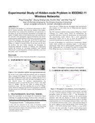
Fig. 1.<br />
N 3<br />
N1<br />
N2<br />
Two way relay channel<br />
<strong>and</strong> classification of PNC. Section III puts forth the concept<br />
of our new l<strong>in</strong>k-by-l<strong>in</strong>k coded PNC scheme, while Section<br />
IV presents a specific design of the CNC decoder for it.<br />
We <strong>in</strong>vestigate the relative performance of CNC schemes <strong>in</strong><br />
Section V. Section VI concludes this paper.<br />
II. SYSTEM MODEL AND DEFINITIONS<br />
A. <strong>System</strong> Model<br />
We consider the two-way relay channel as shown <strong>in</strong> Fig.1,<br />
<strong>in</strong> which nodes N 1 <strong>and</strong> N 2 exchange <strong>in</strong>formation <strong>with</strong> the<br />
help of relay node N 3 . We assume that all nodes are halfduplex,<br />
i.e., a node cannot receive <strong>and</strong> transmit simultaneously.<br />
This is an assumption aris<strong>in</strong>g from practical considerations<br />
because it is difficult for the wireless nodes to remove the<br />
strong <strong>in</strong>terference of its own transmitt<strong>in</strong>g signal from the<br />
received signal. We also assume that there is no direct l<strong>in</strong>k<br />
between node N 1 <strong>and</strong> N 2 . An example <strong>in</strong> practice is a satellite<br />
communication system <strong>in</strong> which the two end nodes on the<br />
earth can only communicate <strong>with</strong> each other via the relay<br />
satellite.<br />
In this paper, S i denotes the uncoded source packet of<br />
node N i ; X i denotes the correspond<strong>in</strong>g packet after channel<br />
cod<strong>in</strong>g; A i denotes the correspond<strong>in</strong>g transmitted packets after<br />
BPSK modulation; <strong>and</strong> Y i denotes the received base-b<strong>and</strong><br />
packet at node N i . A lowercase letter, s i ∈ {0, 1}, a i ∈<br />
{−1, 1}, x i ∈{0, 1}, or y i ∈ R, denotes one symbol <strong>in</strong> the<br />
correspond<strong>in</strong>g packet. We use Γ i to denote the channel cod<strong>in</strong>g<br />
scheme adopted by node N i . Specifically,<br />
X i =Γ i (S i ) S i =Γ −1<br />
i (X i ) (1)<br />
We consider a two-phase transmission scheme consist<strong>in</strong>g of<br />
an upl<strong>in</strong>k phase <strong>and</strong> a downl<strong>in</strong>k phase. In the upl<strong>in</strong>k phase, N 1<br />
<strong>and</strong> N 2 transmit to N 3 simultaneously. Therefore, N 3 receives<br />
y ′ 3 = √ P 1 a 1 + √ P 2 a 2 + w ′ 3<br />
= √ P 1 (1 − 2x 1 )+ √ P 2 (1 − 2x 2 )+w ′ 3<br />
s.t. P 1 + P 2 =2<br />
where w 3 ′ is the noise at N 3, assumed to be Gaussian <strong>with</strong><br />
variance σ 2 (identical for all the three nodes); <strong>and</strong> P i takes the<br />
transmit power <strong>and</strong> channel fad<strong>in</strong>g effect of N i <strong>in</strong>to account.<br />
In (1), perfect synchronization is assumed. Synchronization is<br />
an important issue <strong>in</strong> PNC <strong>and</strong> other wireless communication<br />
systems. More details about it can be found <strong>in</strong> [5] <strong>and</strong> the<br />
references there<strong>in</strong>. With coherent soft decision demodulation,<br />
the received signal at N 3 can be expressed as<br />
y 3 = −<br />
(y 3 ′ − √ P 1 − √ )<br />
P 2<br />
(2)<br />
= √ 4P 1 x 1 + √ 4P 2 x 2 + w 3<br />
(3)<br />
Authorized licensed use limited to: Ch<strong>in</strong>ese University of Hong Kong. Downloaded on August 26, 2009 at 23:26 from IEEE Xplore. Restrictions apply.
790 IEEE JOURNAL ON SELECTED AREAS IN COMMUNICATIONS, VOL. 27, NO. 5, JUNE 2009<br />
where the Gaussian noise w 3 = −w ′ 3 ∈ N(0,σ 2 ) <strong>and</strong><br />
its vector version is W 3 . Hereafter, we write the received<br />
packet Y 3 as a function of the transmitted packet X 1 + X 2<br />
<strong>with</strong>out explicit explanation of the modulation-demodulation<br />
procedure.<br />
In the downl<strong>in</strong>k phase, N 3 generates a new packet X 3 based<br />
on the received packet Y 3 , <strong>and</strong> broadcasts it to both N 1 <strong>and</strong><br />
N 2 . We can write the signals received by N 1 <strong>and</strong> N 2 as<br />
y 1 = √ 4P 3 x 3 + w 1 y 2 = √ 4P 3 x 3 + w 2 (4)<br />
where, for simplicity, the channel ga<strong>in</strong>s for the channels from<br />
the relay node to N 1 <strong>and</strong> to N 2 are assumed to be the same.<br />
The target <strong>in</strong>formation X 1 (X 2 ) will be decoded from Y 2 (Y 1 )<br />
at N 2 (N 1 ) <strong>with</strong> the help of its self-<strong>in</strong>formation. In general,<br />
X 3 must be a function of Y 3 , which is <strong>in</strong> turn a function of<br />
X 1 <strong>and</strong> X 2 .Thatis,X 3 = f(Y 3 ) (note that f may <strong>in</strong>volve<br />
complex transformation <strong>and</strong> may not be a simple mapp<strong>in</strong>g).<br />
Part B below def<strong>in</strong>es <strong>and</strong> classifies PNC.<br />
B. Def<strong>in</strong>itions <strong>and</strong> classification of PNC<br />
Def<strong>in</strong>ition 3.1 (PNC): Physical-layer network cod<strong>in</strong>g is<br />
the cod<strong>in</strong>g operation which transforms the received baseb<strong>and</strong><br />
packet at N 3 , Y 3 = √ 4P 1 X 1 + √ 4P 2 X 2 + W 3 , to a networkcoded<br />
packet X 3 = f(Y 3 ) for relay, where X 1 <strong>and</strong> X 2 are<br />
the packets transmitted by N 1 <strong>and</strong> N 2 simultaneously to N 3 .<br />
If the relay node does not perform any channel decod<strong>in</strong>g <strong>and</strong><br />
re-encod<strong>in</strong>g operation (only the source node performs channel<br />
encod<strong>in</strong>g <strong>and</strong> the s<strong>in</strong>k node performs channel decod<strong>in</strong>g), the<br />
PNC transformation <strong>in</strong> Def<strong>in</strong>ition 3.1 then works <strong>in</strong> a symbolby-symbol<br />
manner. The uppercase letters denot<strong>in</strong>g packets<br />
could be replaced by lowercase letters denot<strong>in</strong>g symbols <strong>in</strong><br />
Def<strong>in</strong>ition 3.1. We refer to this as end-to-end coded PNC.<br />
Interested readers are referred to [14] for a study of end-toend<br />
coded PNC.<br />
By contrast, if channel cod<strong>in</strong>g is <strong>in</strong>volved <strong>in</strong> the PNC<br />
transformation at the relay, each symbol <strong>in</strong> X 3 may depend<br />
on other symbols <strong>in</strong> Y 3 due to the correlation created by the<br />
channel cod<strong>in</strong>g. Therefore, the PNC transformation operates<br />
on a packet-by-packet basis, <strong>and</strong> the wireless upl<strong>in</strong>ks <strong>and</strong><br />
downl<strong>in</strong>ks between the end nodes <strong>and</strong> the relay are separately<br />
protected by channel cod<strong>in</strong>g. We refer this set-up as l<strong>in</strong>k-byl<strong>in</strong>k<br />
coded PNC. Because both S 1 <strong>and</strong> S 2 areassumedtobe<br />
over GF(2) <strong>in</strong> this paper, we only consider network cod<strong>in</strong>g<br />
over GF(2) <strong>and</strong> hence the only nontrivial network cod<strong>in</strong>g<br />
operation is to form the modulo-2 sum (XOR) of the packet<br />
S 1 <strong>and</strong> S 2 .AndX 3 will be <strong>in</strong> the form of Γ 3 (S 1 ⊕ S 2 ).The<br />
formal def<strong>in</strong>ition of l<strong>in</strong>k-by-l<strong>in</strong>k coded PNC is as follows:<br />
Def<strong>in</strong>ition 3.2 (L<strong>in</strong>k-by-l<strong>in</strong>k Coded PNC): L<strong>in</strong>k-by-l<strong>in</strong>k<br />
coded PNC is the cod<strong>in</strong>g operation which transforms the<br />
received baseb<strong>and</strong> packet at N 3 , Y 3 = √ 4P 1 X 1 + √ 4P 2 X 2 +<br />
W 3 , <strong>in</strong>to a network-coded packet X 3 = Γ 3 (S 1 ⊕ S 2 ) =<br />
Γ 3 (h(Y 3 )) for relay, where X 1 <strong>and</strong> X 2 are the packets<br />
transmitted by N 1 <strong>and</strong> N 2 simultaneously to N 3 .<br />
Unless stated otherwise, PNC hereafter means l<strong>in</strong>k-by-l<strong>in</strong>k<br />
coded PNC. Once S 1 ⊕ S 2 is obta<strong>in</strong>ed, it is a straightforward<br />
process to channel-encode S 1 ⊕ S 2 to obta<strong>in</strong> Γ 3 (S 1 ⊕ S 2 ).<br />
Therefore, key to PNC is the CNC process at the relay to<br />
obta<strong>in</strong> S 1 ⊕ S 2 = h(Y 3 ) from Y 3 ,def<strong>in</strong>ed as<br />
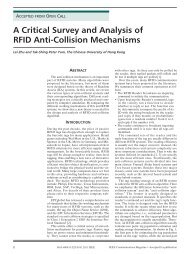
Fig. 2.<br />
y 3<br />
P s , s<br />
1 2<br />
<strong>Channel</strong><br />
Decode<br />
Block diagram of CNC1.<br />
1 2<br />
XOR<br />
s<br />
⊕ s<br />
Def<strong>in</strong>ition 3.3 (CNC): The <strong>Channel</strong>-decod<strong>in</strong>g-Network-<br />
<strong>Cod<strong>in</strong>g</strong> process (CNC) is the process at the relay that transforms<br />
Y 3 = √ 4P 1 X 1 + √ 4P 2 X 2 + W 3 to S 1 ⊕ S 2 .<br />
Indeed, the study of this paper focuses on the CNC process,<br />
as the efficient implementation of it holds the key to the<br />
performance of a good l<strong>in</strong>k-by-l<strong>in</strong>k coded PNC system. For<br />
simplicity, we assume P 1 = P 2 =1hereafter to focus on<br />
the basic idea of the proposed CNC. The discussion related<br />
to unequal power allocation (or where channel fad<strong>in</strong>g effects<br />
are taken <strong>in</strong>to account) are given <strong>in</strong> the appendix.<br />
III. A NOVEL LINK-BY-LINK CODED PNC<br />
In this section, we first briefly <strong>in</strong>troduce two straightforward<br />
<strong>and</strong> well studied CNC schemes, CNC1 <strong>and</strong> CNC2. After that,<br />
we propose a new scheme, Arithmetic-sum CNC (ACNC),<br />
that performs the channel decod<strong>in</strong>g specifically designed for<br />
network cod<strong>in</strong>g mapp<strong>in</strong>g at the relay node.<br />
A. CNC Design1 (CNC1)<br />
In CNC1, the relay N 3 first decodes S 1 <strong>and</strong> S 2 from Y 3<br />
separately. Note that this is <strong>in</strong> fact the well known multipleaccess<br />
problem [7, Theorem 14.3.1]. With st<strong>and</strong>ard channel<br />
decod<strong>in</strong>g, the relay can first decode one packet, say S 1 , while<br />
regard<strong>in</strong>g the other packet S 2 as <strong>in</strong>terference, <strong>and</strong> can then<br />
decode S 2 after remov<strong>in</strong>g the decoded <strong>in</strong>formation S 1 from<br />
the received signal. Suppos<strong>in</strong>g SISO (soft <strong>in</strong>put soft output)<br />
channel decoder is used, we can obta<strong>in</strong> the PMF (probability<br />
mass function) of the pair (s 1 , s 2 ), denoted by P s1,s 2<br />
(a, b) =<br />
Pr(s 1 = a, s 2 = b|Y 3 ). Then, the relay node can directly<br />
comb<strong>in</strong>e them <strong>with</strong> network cod<strong>in</strong>g (XOR) to obta<strong>in</strong> S 1 ⊕ S 2 ,<br />
as<br />
{ 1 if Ps1,s<br />
s 1 ⊕ s 2 =<br />
2<br />
(1, 0) + P s1,s 2<br />
(0, 1) ≥ 0.5<br />
(5)<br />
0 else<br />
The block diagram of this scheme is shown <strong>in</strong> Fig. 2.<br />
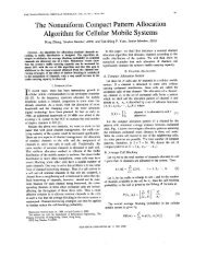
B. CNC Design2 (CNC2)<br />
In CNC2, the relay N 3 first estimates the PMF of x 1 ⊕ x 2 ,<br />
denoted by P x1⊕x 2<br />
(a) = Pr(x 1 ⊕ x 2 = a|y 3 ), from the<br />
received symbol y 3 <strong>with</strong> MMSE estimation (see [14] for<br />
details). Us<strong>in</strong>g the same l<strong>in</strong>ear channel codes at both end<br />
nodes (e.g., LDPC code is l<strong>in</strong>ear under b<strong>in</strong>ary addition, <strong>and</strong><br />
the lattice code is l<strong>in</strong>ear under modulo addition [10, 15]), the<br />
packet X 1 ⊕ X 2 is the codeword of S 1 ⊕ S 2 . By decod<strong>in</strong>g the<br />
estimate of X 1 ⊕ X 2 ,i.e.P x1⊕x 2<br />
,directly <strong>with</strong> a soft <strong>in</strong>put<br />
decoder, the relay can obta<strong>in</strong> S 1 ⊕ S 2 . The block diagram of<br />
CNC2 is shown <strong>in</strong> Fig. 3.<br />
CNC1 <strong>and</strong> CNC2 do not satisfy the two good-CNC design<br />
pr<strong>in</strong>ciples mentioned <strong>in</strong> the <strong>in</strong>troduction. By decod<strong>in</strong>g S 1 <strong>and</strong><br />
S 2 explicitly, CNC1 obta<strong>in</strong>s extraneous <strong>in</strong>formation unrelated<br />
to S 1 ⊕ S 2 , result<strong>in</strong>g <strong>in</strong> unnecessary power penalty. In CNC2,<br />
the PNC mapp<strong>in</strong>g from symbol y 3 to the PMF of x 1 ⊕ x 2<br />
Authorized licensed use limited to: Ch<strong>in</strong>ese University of Hong Kong. Downloaded on August 26, 2009 at 23:26 from IEEE Xplore. Restrictions apply.
ZHANG <strong>and</strong> LIEW: CHANNEL CODING AND DECODING IN A RELAY SYSTEM OPERATED WITH PHYSICAL-LAYER NETWORK CODING 791<br />
Fig. 3.<br />
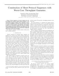
Fig. 4.<br />
y 3 Px<br />
1 ⊕ x<br />
s<br />
2<br />
1<br />
⊕ s 2<br />
PNC<br />
mapp<strong>in</strong>g<br />
Block diagram of CNC2.<br />
<strong>Channel</strong><br />
Decode<br />
P +<br />
<strong>Channel</strong><br />
Decode<br />
y 3 s 1 s2<br />
s 1<br />
⊕ s 2<br />
Block diagram of ACNC.<br />
PNC<br />
Mapp<strong>in</strong>g<br />
discards useful <strong>in</strong>formation related to the decod<strong>in</strong>g of the<br />
whole packet S 1 ⊕S 2 . Our new scheme, Arithmetic-sum CNC<br />
design (ACNC), attempts to follow the two design pr<strong>in</strong>ciples.<br />
C. Arithmetic-sum CNC Design (ACNC)<br />
Our Arithmetic-sum CNC design, ACNC, works as follows.<br />
The relay first decodes Y 3 <strong>in</strong>to to obta<strong>in</strong> the PMF ofs 1 + s 2 ,<br />
denoted by P s1+s 2<br />
(a) =Pr(s 1 +s 2 |Y 3 ). Then, the relay could<br />
obta<strong>in</strong> the target <strong>in</strong>formation <strong>with</strong> the follow<strong>in</strong>g PNC mapp<strong>in</strong>g:<br />
{<br />
1 if Ps1+s<br />
s 1 ⊕ s 2 =<br />
2<br />
(1) ≥ 0.5<br />
. (6)<br />
0 else<br />
Remark 1: From (6), we can see that the relay only<br />
needs to correctly decode the sign of P s1+s 2<br />
(1) −<br />
P s1+s 2<br />
(2) − P s1+s 2<br />
(0). The <strong>in</strong>dividual probabilities of<br />
P s1+s 2<br />
(1), P s1+s 2<br />
(2) <strong>and</strong> P s1+s 2<br />
(0) are not necessary.<br />
The relay node f<strong>in</strong>ally encodes S 1 ⊕ S 2 <strong>with</strong> st<strong>and</strong>ard<br />
channel encoder <strong>and</strong> broadcasts it to both end nodes. The<br />
block diagram of this scheme is shown <strong>in</strong> Fig. 4.<br />
We can see the advantages of ACNC as follows. First, <strong>in</strong><br />
ACNC the relay directly decodes the received packet Y 3 to<br />
make full use of the <strong>in</strong>formation <strong>and</strong> dependency of symbols<br />
<strong>with</strong><strong>in</strong> the packet; by contrast, the symbol-level PNC mapp<strong>in</strong>g<br />
<strong>in</strong> CNC2 neglects the dependency among symbols created<br />
by the channel code. Second, <strong>in</strong> ACNC the channel decoder<br />
of the relay obta<strong>in</strong>s the PMF of s 1 + s 2 which can be<br />
easily transformed to s 1 ⊕ s 2 by symbol-level PNC mapp<strong>in</strong>g;<br />
by contrast, obta<strong>in</strong><strong>in</strong>g s 1 <strong>and</strong> s 2 explicitly as <strong>in</strong> CNC1 is<br />
unnecessary <strong>and</strong> such extraneous <strong>in</strong>formation constra<strong>in</strong>s the<br />
reliable transmission rates of both s 1 <strong>and</strong> s 2 .<br />
The above <strong>in</strong>tuition <strong>in</strong>dicates that ACNC should perform<br />
best among the three l<strong>in</strong>k-by-l<strong>in</strong>k coded PNC schemes. In the<br />
Appendix of [19], we exam<strong>in</strong>e the three CNC schemes from<br />
an <strong>in</strong>formation-theoretic viewpo<strong>in</strong>t. By assum<strong>in</strong>g the existence<br />
of the special channel decoder needed <strong>in</strong> ACNC, <strong>and</strong> that<br />
it can reliably decode S 1 + S 2 <strong>with</strong> a rate approach<strong>in</strong>g the<br />
mutual <strong>in</strong>formation of the channel, we show that ACNC can<br />
substantially outperform both CNC1 <strong>and</strong> CNC2.<br />
However, the special <strong>and</strong> practical channel decoder as<br />
needed <strong>in</strong> ACNC is completely new <strong>and</strong> has not been studied<br />
before. It is motivated by the special requirement of jo<strong>in</strong>t<br />
channel cod<strong>in</strong>g <strong>and</strong> physical layer network cod<strong>in</strong>g. In the next<br />
section, we propose a specific decod<strong>in</strong>g algorithm for ACNC.<br />
IV. A NOVEL CHANNEL CODING SCHEME FOR ACNC<br />
The analysis <strong>in</strong> the Appendix of [19] shows that CNC1 <strong>and</strong><br />
CNC2 outperform non-PNC Straightforward Network <strong>Cod<strong>in</strong>g</strong><br />
Accumulate<br />
S i Repeat q Interleave<br />
U i + D<br />
X i<br />
Fig. 5.<br />
Encoder of st<strong>and</strong>ard RA codes.<br />
(SNC) significantly. However, there is still a significant gap<br />
between their performance <strong>and</strong> the theoretical upper bound.<br />
CNC1 underperforms <strong>in</strong> the high SNR region; CNC2 underperforms<br />
<strong>in</strong> the low SNR region; <strong>and</strong> they both underperform<br />
when SNR is <strong>in</strong> the vic<strong>in</strong>ity of 0 dB. ACNC, on the other h<strong>and</strong>,<br />
has the potential to achieve good performance for all range of<br />
SNR. Motivated as such, this section proposes a new channel<br />
cod<strong>in</strong>g scheme for ACNC based on Repeat Accumulate (RA)<br />
code.<br />
Although we focus on regular RA codes <strong>in</strong> this paper, extensions<br />
to other channel codes, such as LDPC codes <strong>and</strong> Turbo<br />
codes, are straightforward. RA codes were first proposed <strong>in</strong><br />
[12]. They can be regarded as special LDPC codes whose<br />
decod<strong>in</strong>g operation are of low complexity, or special Turbo<br />
codes whose encod<strong>in</strong>g operation are of l<strong>in</strong>ear complexity.<br />
Despite its simple encod<strong>in</strong>g <strong>and</strong> decod<strong>in</strong>g structure, RA codes<br />
(especially some new versions of RA codes, such as IRA <strong>in</strong><br />
[13]) can approach the Shannon capacity of the po<strong>in</strong>t-to-po<strong>in</strong>t<br />
channel.<br />
We now <strong>in</strong>troduce our novel channel decod<strong>in</strong>g scheme <strong>in</strong><br />
ACNC to perform the process<strong>in</strong>g Y 3 → S 1 + S 2 for an<br />
implementation of ACNC. The encoder at N 1 <strong>and</strong> N 2, <strong>and</strong><br />
the decoder at the N 3 are as follows:<br />
A. Encoder at N 1 <strong>and</strong> N 2 :<br />
We assume N 1 <strong>and</strong> N 2 use the traditional encoder of RA<br />
codes. This means that the modification at the transmitter is<br />
not needed. The RA encoder has a very simple structure. As<br />
illustrated <strong>in</strong> Fig. 5, the <strong>in</strong>put packet S i of the encoder is first<br />
repeated q (q ≥ 3) times. After that, the bits are <strong>in</strong>terleaved<br />
<strong>and</strong> accumulated by b<strong>in</strong>ary summation ⊕ to generate the<br />
codeword X i . We further assume that the <strong>in</strong>terleave pattern<br />
<strong>and</strong> the repeat factor q are the same for the two end nodes.<br />
B. Decoder at N 3 :<br />
The decoder at N 3 is different from the traditional RA<br />
decoder. This part provides the design of such a decoder<br />
along the follow<strong>in</strong>g three steps: 1) construct a virtual encoder<br />
correspond<strong>in</strong>g to the decoder; 2) construct the Tanner graph<br />
of the virtual code; 3) design the belief propagation algorithm<br />
based on the Tanner graph.<br />
1) Step 1: Virtual Encoder: For ACNC, the decoder at<br />
the relay can be regarded as process<strong>in</strong>g the superposition of<br />
the two simultaneously received signals from N 1 <strong>and</strong> N 2 to<br />
generate the superposition of the two <strong>in</strong>puts of the encoders<br />
at N 1 <strong>and</strong> N 2 . In the absence of noise, the received signals<br />
are the superposition of the two outputs of the encoders at N 1<br />
<strong>and</strong> N 2 . Thus, the decod<strong>in</strong>g process at N 3 can be viewed as<br />
the <strong>in</strong>verse of the superposition of the encod<strong>in</strong>g processes at<br />
N 1 <strong>and</strong> N 2 . As such, the decoder at N 3 could conceptually<br />
be viewed as the decoder of a virtual encoder whose <strong>in</strong>put S v<br />
<strong>and</strong> output X v are<br />
Authorized licensed use limited to: Ch<strong>in</strong>ese University of Hong Kong. Downloaded on August 26, 2009 at 23:26 from IEEE Xplore. Restrictions apply.
792 IEEE JOURNAL ON SELECTED AREAS IN COMMUNICATIONS, VOL. 27, NO. 5, JUNE 2009<br />
Accumulate<br />
S v Repeat q Interleave<br />
U X v f<br />
v<br />
Fig. 6.<br />
The virtual encoder for ACNC.<br />
S v = S 1 + S 2 X v = X 1 + X 2 (7)<br />
The design of the decoder is <strong>in</strong>timately tied to the structure<br />
of this virtual encoder. As shown <strong>in</strong> Fig. 6, the virtual encoder<br />
has the same structure as the RA encoder <strong>in</strong> Fig. 5 except that<br />
the b<strong>in</strong>ary summation is now replaced by a general function f.<br />
Let us derive f based on the specification <strong>in</strong> (7). Accord<strong>in</strong>gly,<br />
the function f <strong>in</strong> Fig. 6 needs to satisfy<br />
x v [k] =f(x v [k − 1],u v [k]) = x 1 [k]+x 2 [k]<br />
(8)<br />
when s v [j] =s 1 [j]+s 2 [j]<br />
where x i [k] is the k-th coded bit of node N i , u i [k] is the<br />
k-th <strong>in</strong>terleaved bit of node N i <strong>and</strong>s i [j] =u i [k] is the j-th<br />
<strong>in</strong>formation bit of N i , <strong>and</strong> the <strong>in</strong>dex j is determ<strong>in</strong>ed by the<br />
<strong>in</strong>terleaver, which is the same for both the end nodes’ encoders<br />
<strong>and</strong> for the virtual encoder. Based on Fig. 5, the relations<br />
between x 1 [k], x 2 [k] <strong>and</strong> s 1 [j], s 2 [j] can be respectively<br />
expressed as<br />
x 1 [k] =x 1 [k − 1] ⊕ u 1 [k] =x 1 [k − 1] ⊕ s 1 [j]<br />
(9)<br />
x 2 [k] =x 2 [k − 1] ⊕ u 2 [k] =x 2 [k − 1] ⊕ s 2 [j]<br />
Comb<strong>in</strong><strong>in</strong>g (8) <strong>and</strong> (9), we can obta<strong>in</strong> the expression of the<br />
function f as<br />
x v [k] =f(x v [k − 1],u v [k])<br />
= x⎧<br />
1 [k − 1] ⊕ s 1 [j]+x 2 [k − 1] ⊕ s 2 [j]<br />
0 if (x 1 + x 2 )[k − 1] = 2, (s 1 + s 2 )[j] =2<br />
1 if (x 1 + x 2 )[k − 1] = 2, (s 1 + s 2 )[j] =1<br />
2 if (x 1 + x 2 )[k − 1] = 2, (s 1 + s 2 )[j] =0<br />
⎪⎨ 1 if (x 1 + x 2 )[k − 1] = 1, (s 1 + s 2 )[j] =2<br />
= 0 or 2 if (x 1 + x 2 )[k − 1] = 1, (s 1 + s 2 )[j] =1<br />
1 if (x 1 + x 2 )[k − 1] = 1, (s 1 + s 2 )[j] =0<br />
2 if (x 1 + x 2 )[k − 1] = 0, (s 1 + s 2 )[j] =2<br />
1 if (x 1 + x 2 )[k − 1] = 0, (s 1 + s 2 )[j] =1<br />
⎪⎩<br />
0 if (x 1 + x 2 )[k − 1] = 0, (s 1 + s 2 )[j] =0<br />
(10)<br />
where (s 1 + s 2 )[i] =s 1 [i]+s 2 [i], (x 1 + x 2 )[i] =x 1 [i]+x 2 [i].<br />
It is easy to verify that the function f <strong>in</strong> (10) satisfies the<br />
follow<strong>in</strong>g two properties:<br />
(a): f(a, b) =f(b, a)<br />
(b): if c = f(a, b), thena = f(c, b),b= f(c, a)<br />
for a, b, c ∈ {0, 1, 2}. The same properties are found <strong>in</strong><br />
the traditional RA code where the accumulate function is<br />
XOR. Indeed, underly<strong>in</strong>g the beauty of the RA encod<strong>in</strong>g <strong>and</strong><br />
decod<strong>in</strong>g mechanisms are properties (a) <strong>and</strong> (b).<br />
Remark 2: From (10), we can see that the probability of<br />
x v [k] =2<strong>and</strong> the probability of x v [k] =0do not depend on<br />
the <strong>in</strong>formation sequence S 1 + S 2 for any k>0 when given<br />
x v [k] ≠1<strong>and</strong> x v [0] = 1. Due to the two symmetric properties<br />
(a) <strong>and</strong> (b) of f, the decoded symbol s 1 [k]+s 2 [k] would also<br />
equal 0 or 2 <strong>in</strong> a r<strong>and</strong>om way when it does not equal 1.<br />
D<br />
S=S 1 +S 2 C X=X 1 +X 2 Y<br />
.<br />
.<br />
.<br />
Fig. 7.<br />
I<br />
N<br />
T<br />
E<br />
R<br />
L<br />
E<br />
A<br />
V<br />
E<br />
R<br />
f<br />
f<br />
f<br />
.<br />
.<br />
.<br />
f<br />
Tanner graph of the virtual RA code <strong>in</strong> ACNC.<br />
.<br />
.<br />
.<br />
.<br />
.<br />
.<br />
f<br />
Information Node<br />
Check Node<br />
Code Node<br />
Evidence Node<br />
However, this is <strong>in</strong>nocuous to the decod<strong>in</strong>g of s 1 [k] ⊕ s 2 [k].<br />
Also, the fact that s 1 [k] +s 2 [k] =0or 2 <strong>in</strong> a r<strong>and</strong>om way<br />
when s 1 [k] +s 2 [k] ≠ 1 means that the decoder does not<br />
attempt to acquire any extraneous <strong>in</strong>formation.<br />
2) Step 2: Tanner Graph: RA code can be described <strong>with</strong><br />
the well known Tanner graph, which is the basis of the widely<br />
used belief propagation decod<strong>in</strong>g algorithm [16]. Consider<br />
the Tanner graph of the virtual RA code <strong>in</strong> Fig. 7, which<br />
is constructed based on the encoder <strong>in</strong> Fig. 6. In Fig. 7,<br />
an <strong>in</strong>formation node, a vertex belong<strong>in</strong>g to S, corresponds<br />
to an <strong>in</strong>put bit; <strong>and</strong> a code node, a vertex belong<strong>in</strong>g to X,<br />
corresponds to an output bit of the encoder. The <strong>in</strong>formation<br />
<strong>and</strong> code nodes are referred to as variable nodes. An evidence<br />
node, a vertex belong<strong>in</strong>g to Y , corresponds to a received<br />
symbol <strong>in</strong> Y 3 . In the Tanner graph, a check node, a vertex<br />
belong<strong>in</strong>g to C, represents a “local constra<strong>in</strong>t” on a subset of<br />
variable nodes, i.e., the values of the variable nodes connected<br />
to a check node should satisfy a predef<strong>in</strong>ed equation. For<br />
example, the value of any one of the three variable nodes<br />
connected to one check node <strong>in</strong> Fig. 7 should be the output of<br />
the f function <strong>with</strong> the values of the other two variable nodes<br />
as <strong>in</strong>puts.<br />
Generally speak<strong>in</strong>g, the encod<strong>in</strong>g <strong>and</strong> decod<strong>in</strong>g operation<br />
based on the Tanner graph is as follows. For encod<strong>in</strong>g, the<br />
Tanner graph is read from left to right. That is, symbols are<br />
passed from left to right. For decod<strong>in</strong>g, the Tanner graph could<br />
be read backward from right to left. If there were no noise,<br />
given (x 1 + x 2 )[k] for all k received at the evidence nodes,<br />
(s 1 + s 2 )[j] for all j could be recovered at the <strong>in</strong>formation<br />
nodes <strong>in</strong> one iteration of message pass<strong>in</strong>g from right to left.<br />
The messages (a message is associated <strong>with</strong> one directional<br />
edge <strong>in</strong> the Tanner Graph) may simply conta<strong>in</strong> the exact values<br />
of the symbol (x 1 +x 2 )[k] or (s 1 +s 2 )[j]. With noise, <strong>in</strong>stead<br />
of pass<strong>in</strong>g the symbol value from one node to the next, the a<br />
posteriori probabilities associated <strong>with</strong> the values are passed.<br />
Multiple iterations of message pass<strong>in</strong>g from right to left as <strong>in</strong><br />
Fig. 8(a) <strong>and</strong> Fig. 8(b), <strong>and</strong> then from left to right as <strong>in</strong> Fig.<br />
8(c) <strong>and</strong> Fig. 8(d), are needed [16, 17]. The idea is that after<br />
several iterations, the probabilities will converge <strong>and</strong> we could<br />
decode (s 1 + s 2 )[j] basedonthem.<br />
Authorized licensed use limited to: Ch<strong>in</strong>ese University of Hong Kong. Downloaded on August 26, 2009 at 23:26 from IEEE Xplore. Restrictions apply.
ZHANG <strong>and</strong> LIEW: CHANNEL CODING AND DECODING IN A RELAY SYSTEM OPERATED WITH PHYSICAL-LAYER NETWORK CODING 793<br />
c<br />
f<br />
c’<br />
f<br />
s<br />
Fig. 8.<br />
x<br />
(a)<br />
(c)<br />
f<br />
f<br />
f<br />
c<br />
c’<br />
c”<br />
y<br />
s<br />
s<br />
c<br />
f<br />
(b)<br />
Message updat<strong>in</strong>g steps <strong>in</strong> one round of iteration.<br />
3) Step 3: <strong>Decod<strong>in</strong>g</strong> algorithm: With the Tanner graph <strong>in</strong><br />
Fig. 7, we can design the particular decod<strong>in</strong>g algorithm of the<br />
virtual encoder us<strong>in</strong>g a message pass<strong>in</strong>g mechanism similar to<br />
the generic message pass<strong>in</strong>g mechanism <strong>in</strong> [16]. The message<br />
form <strong>and</strong> the message update rules specific to our system are<br />
specified below.<br />
We first rewrite the k-th received symbol at N 3 <strong>in</strong> (2) as<br />
c<br />
f<br />
(d)<br />
y 3 [k] =(1− 2x 1 [k]) + (1 − 2x 2 [k]) + n 3 (11)<br />
The follow<strong>in</strong>g algorithm can be extended to the case of<br />
general modulation as long as the received q-ary signal can<br />
be decomposed <strong>in</strong>to log 2 q bits.<br />
Let P [h, t] denote the message passed between a check node<br />
<strong>and</strong> a variable node (<strong>in</strong>formation node or code node). The<br />
message is associated <strong>with</strong> the edge from node h to node t,<br />
where one of h or t is a variable node, <strong>and</strong> the other is a<br />
check node. Let P k , k ∈ [1,qN], be the message from the<br />
k-th (ordered from top to bottom as <strong>in</strong> Fig. 7) evidence node<br />
to the k-th code node, where N is the length of the uncoded<br />
packet.<br />
Message form:<br />
P [h, t] = (p 0 ,p 1 ,p 2 ) is a vector, <strong>in</strong> which p i is the<br />
probability that the correspond<strong>in</strong>g variable node (h or t) takes<br />
on the value of i.<br />
P k =(p 0 ,p 1 ,p 2 ) is a vector, <strong>in</strong> which p i is the probability<br />
that the k-th coded symbol is i given the k-th received symbol.<br />
Message Initial Values:<br />
All the messages associated <strong>with</strong> the edges <strong>in</strong> Fig. 7 are<br />
set to (1/4, 1/2, 1/4) except for the messages on the edges<br />
<strong>in</strong>cident to the evidence nodes, which conta<strong>in</strong> <strong>in</strong>formation on<br />
the received signal. The message from the k-th evidence node<br />
is computed from the received signal y 3 [k] as <strong>in</strong> (12)<br />
where β is ( a normaliz<strong>in</strong>g factor given by ) β =<br />
exp( −(y3[k])2<br />
2σ<br />
) exp( 2y3[k]−2<br />
2 σ<br />
)+exp( −2y3[k]−2<br />
2<br />
σ<br />
)+2 .<br />
2<br />
Message Update Rules:<br />
Parallel to the generic updat<strong>in</strong>g rules <strong>in</strong> [16], we also have<br />
the same message updat<strong>in</strong>g rules at our check nodes <strong>and</strong><br />
variable nodes. Note that the messages from the evidence<br />
x<br />
x<br />
x’<br />
x’<br />
nodes to the code nodes rema<strong>in</strong> the same <strong>with</strong>out be<strong>in</strong>g<br />
changed dur<strong>in</strong>g the iterations of the decod<strong>in</strong>g process.<br />
Update Equations for Output Messages Go<strong>in</strong>g Out of a<br />
Variable Node<br />
This is the case for Fig. 8(a) <strong>and</strong> (c). In the follow<strong>in</strong>g, we<br />
focus on the scenario of Fig. 8(a). The update equations for<br />
the scenario of Fig. 8(c) are similar except that the variable<br />
node is an <strong>in</strong>formation node rather than a code node, <strong>and</strong><br />
the associated probabilities are related to the source symbol<br />
rather than the code symbol. When the probability vectors of<br />
the two <strong>in</strong>put messages, P =(p 0 ,p 1 ,p 2 ) <strong>and</strong> Q =(q 0 ,q 1 ,q 2 )<br />
(associated <strong>with</strong> the edge from y to x <strong>and</strong> the edge from c’ to<br />
x, respectively), arrive at a code node of degree three (except<br />
the lowest code node), the probability that the code symbol is<br />
0 is obta<strong>in</strong>ed as follows:<br />
Pr(P,Q|x=0) Pr(x=0)<br />
Pr(x =0|P, Q) =<br />
=<br />
Pr(P,Q)<br />
Pr(P |Q,x=0) Pr(Q|x=0) Pr(x=0)<br />
Pr(P,Q)<br />
Pr(P |x=0) Pr(Q|x=0) Pr(x=0)<br />
Pr(P,Q)<br />
= (13)<br />
Pr(x=0|P )Pr(x=0|Q)Pr(P )Pr(Q)<br />
=<br />
Pr(P,Q)Pr(x=0)<br />
=4βp 0 q 0<br />
Pr(P )Pr(Q)<br />
where β =<br />
Pr(P,Q)<br />
<strong>and</strong> the two <strong>in</strong>put messages are assumed<br />
to be <strong>in</strong>dependent given the value of the variable node,<br />
i.e., Pr(P |Q, x) =Pr(P |x). Giventhel-depth neighborhood<br />
of the edge is cycle free (cycle free condition), this assumption<br />
is true for iterations up to l <strong>in</strong> the decod<strong>in</strong>g algorithm. As <strong>in</strong><br />
the proof for the LDPC codes <strong>in</strong> [18], the probability that the<br />
cycle free condition is true for our coder <strong>in</strong> Fig. 7 should also<br />
go to 1 as the length of the code goes to <strong>in</strong>f<strong>in</strong>ity. That is, l<br />
becomes larger <strong>and</strong> larger.<br />
In a similar way, we can obta<strong>in</strong> that Pr(x =1|P, Q) =<br />
2βp 1 q 1 <strong>and</strong> Pr(x = 2|P, Q) = 4βp 2 q 2 . Thus, the output<br />
message at the variable node is<br />
VAR(P, Q) =4β(p 0 q 0 ,p 1 q 1 /2,p 2 q 2 ) (14)<br />
S<strong>in</strong>ce the summation of the three probabilities should be 1,<br />
we require β =(p 0 q 0 + p 1 q 1 /2+p 2 q 2 )/4 for normalization.<br />
For the lowest code node <strong>in</strong> Fig. 7, the output message is<br />
always the same at the <strong>in</strong>put message from the last evidence<br />
node, which rema<strong>in</strong>s constant throughout the iterations.<br />
Update Equations for Output Messages Go<strong>in</strong>g Out of Check<br />
Nodes:<br />
This is the case for Fig. 8(b) <strong>and</strong> (d) except that the<br />
accumulate function is f <strong>in</strong> (10) <strong>in</strong>stead of ⊕. We focus on<br />
the scenario of Fig. 8(b) here. Consider a check node below<br />
the topmost check node. Based on the f def<strong>in</strong>ed <strong>in</strong> (10), <strong>and</strong><br />
us<strong>in</strong>g similar computation as <strong>in</strong> (13), the probability that the<br />
<strong>in</strong>formation node symbol is 0 given the two <strong>in</strong>put messages<br />
P =(p 0 ,p 1 ,p 2 ) <strong>and</strong> Q =(q 0 ,q 1 ,q 2 ) (associated <strong>with</strong> the<br />
edge from x to c <strong>and</strong> the edge from x ′ to c, respectively) is<br />
Pr(s =0|P, Q)<br />
=Pr(x =0,x ′ =0|P, Q)+Pr(x =2,x ′ =2|P, Q)<br />
+ 1 2 Pr(x =1,x′ =1|P, Q)<br />
=Pr(x =0|P )Pr(x ′ =0|Q)+Pr(x =2|P )Pr(x ′ =2|Q)<br />
+ 1 2 Pr(x =1|P )Pr(x′ =1|Q)<br />
= p 0 q 0 + p 2 q 2 + 1 2 p 1q 1<br />
(15)<br />
Authorized licensed use limited to: Ch<strong>in</strong>ese University of Hong Kong. Downloaded on August 26, 2009 at 23:26 from IEEE Xplore. Restrictions apply.
794 IEEE JOURNAL ON SELECTED AREAS IN COMMUNICATIONS, VOL. 27, NO. 5, JUNE 2009<br />
P k = (p 0 ,p 1 ,p 2 )<br />
= ( Pr((x 1 + x 2 )[k] =0|y 3 [k]),<br />
Pr((x 1 + x 2 )[k] =1|y 3 [k]),<br />
Pr((x 1 + x 2 )[k] =2|y 3 [k]) )<br />
= 1 β<br />
(exp( −(y3[k]−2)2<br />
2σ 2<br />
), 2exp( −(y3[k])2<br />
2σ<br />
), exp( −(y3[k]+2)2<br />
2<br />
2σ<br />
) 2<br />
)<br />
(12)<br />
In a similar way, we can obta<strong>in</strong> that Pr(s =1|P, Q) <strong>and</strong><br />
Pr(s =2|P, Q). As a result, the output message at the check<br />
node is<br />
CHK(P, Q) =(p 0 q 0 + p 1 q 1 /2+p 2 q 2 ,<br />
(16)<br />
p 1 q 2 + p 2 q 1 + p 1 q 0 + p 0 q 1 ,p 0 q 2 + p 1 q 1 /2+p 2 q 0 )<br />
For the topmost check node <strong>in</strong> Fig. 7, the output message is<br />
always the same at the <strong>in</strong>put message from the topmost code<br />
node.<br />
Notable is the fact that the complexity of our updat<strong>in</strong>g rules<br />
<strong>in</strong> (14) <strong>and</strong> (16) is <strong>in</strong>deed just four real-number multiplications<br />
(p 0 q 0 ,p 1 q 1 ,p 0 q 1 <strong>and</strong> p 1 q 0 , others can be obta<strong>in</strong>ed <strong>with</strong> simple<br />
addition), which is same as the complexity of traditional RA<br />
decoder when the same message format is adopted. With<br />
the rules given <strong>in</strong> (14) <strong>and</strong> (16) <strong>and</strong> the <strong>in</strong>itial message<br />
values given <strong>in</strong> (12), the detailed iterative belief propagation<br />
algorithm can be easily constructed as follows:<br />
1) Set all the messages to the <strong>in</strong>itial state.<br />
2) Update messages iteratively as follows (i, ii, iii, <strong>and</strong> iv<br />
below corresponds to the sett<strong>in</strong>gs <strong>in</strong> Fig. 8(a), (b), (c),<br />
<strong>and</strong> (d), respectively):<br />
i Update messages P [x, c] <strong>and</strong> P [x, c ′ ] at all code<br />
nodes x ∈ X, wherec <strong>and</strong> c ′ are neighbor check<br />
nodes to x: Ifx is the last code node at the bottom<br />
of Tanner graph,<br />
P [x, c] =P qN<br />
If x is not the last code node,<br />
P [x, c] =VAR(P k ,P[c ′ ,x])<br />
P [x, c ′ ]=VAR(P k ,P[c, x])<br />
ii Update messages P [c, s] at all check nodes c ∈ C,<br />
where s, x, <strong>and</strong>x ′ are neighbor variable nodes to<br />
c:<br />
If c is the first check node at the top of Tanner<br />
graph,<br />
P [c, s] =P [x, c]<br />
If cis not the first check node at the top<br />
P [c, s] =CHK(P [x, c],P[x ′ ,c])<br />
iii Update messages P [s, c],P[s, c ′ ],P[s, c ′′ ] at all<br />
<strong>in</strong>formation nodes s ∈ S, wherec, c ′ ,<strong>and</strong>c ′′ are<br />
neighbor check nodes to s:<br />
P [s, c] =VAR(P [c ′ ,s],P[c ′′ ,s])<br />
P [s, c ′ ]=VAR(P [c, s],P[c ′′ ,s])<br />
P [s, c ′′ ]=VAR(P [c ′ ,s],P[c, s])<br />
iv Update messages P [c, x] at all check nodes, where<br />
s, x, <strong>and</strong>x ′ are neighbor variable nodes to c: Ifc<br />
is the first check node at the top of Tanner graph,<br />
If c is not the first check node,<br />
P [c, x] =CHK(P [s, c],P[x ′ ,c])<br />
P [c, x ′ ]=CHK(P [s, c],P[x, c])<br />
v Go to step i until some criteria satisfied.<br />
3) When iteration stops, the output message for an <strong>in</strong>formation<br />
node s is given by<br />
P v = VAR(VAR(P [s, c],P[s, c ′ ]),P[s, c ′′ ])<br />
V. NUMERICAL SIMULATION<br />
In this section, we <strong>in</strong>vestigate the performance of ACNC<br />
<strong>with</strong> the above decod<strong>in</strong>g algorithm via numerical simulation.<br />
We set the repeat factor q to 3 <strong>and</strong> the <strong>in</strong>terleave pattern is<br />
r<strong>and</strong>omly selected for each packet, but identical for all the<br />
three schemes. We apply ACNC <strong>and</strong> check the BER (bit error<br />
rate) of the decoded packet S 1 ⊕ S 2 at the relay node. BPSK<br />
modulation is used at both end nodes <strong>and</strong> the power is equally<br />
allocated to them. The noise is AWGN <strong>with</strong> variance σ 2 <strong>and</strong><br />
the SNR is def<strong>in</strong>ed as 1/σ 2 (the total transmit power of the<br />
two end nodes is 2 <strong>and</strong> the average power of each one is 1).<br />
For comparison, we also study the performance of CNC1<br />
<strong>and</strong> CNC2 that use st<strong>and</strong>ard RA code. They use the same<br />
encoder as <strong>in</strong> ACNC, but the decoders at the relays are<br />
different. In CNC1, the two end nodes apply optimal power<br />
allocation as <strong>in</strong> eqn. (A-4) <strong>in</strong> [19]. The relay node obta<strong>in</strong>s<br />
P s1,s 2<br />
by successively decod<strong>in</strong>g Y 3 to S 1 <strong>and</strong> S 2 <strong>with</strong> the<br />
st<strong>and</strong>ard SISO RA decoder sequentially <strong>and</strong> then comb<strong>in</strong>s<br />
them <strong>with</strong> (5). In CNC2, the relay N 3 transforms each symbol<br />
<strong>in</strong> y 3 to P x1⊕x 2<br />
<strong>with</strong> the MMSE estimation as <strong>in</strong> [14] <strong>and</strong> then<br />
channel-decodes X 1 ⊕ X 2 to S 1 ⊕ S 2 us<strong>in</strong>g the st<strong>and</strong>ard RA<br />
decoder.<br />
In Fig. 9, we show the BER performance of the three<br />
schemes under different SNR. In the simulation, the uncoded<br />
packet length is set to 4096 bits <strong>and</strong> the BER is calculated by<br />
averag<strong>in</strong>g over 10,000 packets. The iteration numbers for both<br />
our new decod<strong>in</strong>g algorithm <strong>and</strong> the st<strong>and</strong>ard RA decod<strong>in</strong>g<br />
algorithm are set to 20, 30 or 40. As shown <strong>in</strong> Fig. 9, the<br />
BER of all three schemes decreases <strong>with</strong> the <strong>in</strong>crease <strong>in</strong><br />
SNR <strong>and</strong> the iteration number. ACNC outperforms CNC2 by<br />
about 0.5dB when the BER is <strong>in</strong> the ballpark of 10 −4 ;<strong>and</strong><br />
it outperforms CNC1 by an even larger gap. ACNC <strong>with</strong> 20-<br />
iteration decod<strong>in</strong>g outperforms both CNC1 <strong>and</strong> CNC2 <strong>with</strong><br />
40-iteration decod<strong>in</strong>g.<br />
In Fig. 10, we show the BER performance for different<br />
packet lengths (1024, 4096, <strong>and</strong> 8192 bits) when the iteration<br />
numbers of all three schemes are set to 30. In general, larger<br />
packet length leads to smaller BER for all the schemes. Fig. 10<br />
also shows that for all packet lengths, we cont<strong>in</strong>ue to observe<br />
the outperformance of ACNC over CNC2 by about 0.5 dB<br />
when the BER is 10 −4 ; <strong>and</strong> the outperformance of ACNC<br />
over CNC1 by an even larger gap.<br />
Authorized licensed use limited to: Ch<strong>in</strong>ese University of Hong Kong. Downloaded on August 26, 2009 at 23:26 from IEEE Xplore. Restrictions apply.
ZHANG <strong>and</strong> LIEW: CHANNEL CODING AND DECODING IN A RELAY SYSTEM OPERATED WITH PHYSICAL-LAYER NETWORK CODING 795<br />
10 0 SNR (dB)<br />
10 0 SNR (dB)<br />
10 −1<br />
10 −1<br />
10 −2<br />
10 −2<br />
BER<br />
10 −3<br />
ACNC iteno: 20<br />
ACNC iteno: 30<br />
10 −4 ACNC iteno: 40<br />
CNC1 iteno: 20<br />
CNC1 iteno: 30<br />
10 −5 CNC1 iteno: 40<br />
CNC2 iteno: 20<br />
CNC2 iteno: 30<br />
10 −6 CNC2 iteno: 40<br />
0 0.2 0.4 0.6 0.8 1 1.2 1.4<br />
Fig. 9. BER performance of the CNC1, CNC2, <strong>and</strong> ACNC, under different<br />
numbers of iterations used <strong>in</strong> the belief propagation algorithm.<br />
VI. CONCLUSION AND DISCUSSION<br />
We have <strong>in</strong>vestigated three schemes for l<strong>in</strong>k-by-l<strong>in</strong>k coded<br />
PNC. The relative performance of the three schemes lies <strong>in</strong><br />
the <strong>Channel</strong>-decod<strong>in</strong>g-Network-<strong>Cod<strong>in</strong>g</strong> (CNC) strategies used<br />
at the relay node. In particular, an <strong>in</strong>sight from this paper<br />
is that we should (i) avoid decod<strong>in</strong>g extraneous <strong>in</strong>formation<br />
not related to S 1 ⊕ S 2 ; (ii) make full use of the <strong>in</strong>formation<br />
conta<strong>in</strong>ed <strong>in</strong> Y 3 to help decode the network-coded packets S 1 ⊕<br />
S 2 . Guided by these two pr<strong>in</strong>ciples, an Arithmetic-sum CNC<br />
(ACNC) scheme has been proposed <strong>in</strong> this paper. Specifically,<br />
we provide an implementation of ACNC based on RA code<br />
<strong>and</strong> a special belief propagation decod<strong>in</strong>g algorithm tailored<br />
for PNC mapp<strong>in</strong>g.<br />
For comparison purposes, two conventional CNC schemes,<br />
CNC1 <strong>and</strong> CNC2, have been <strong>in</strong>vestigated. From viewpo<strong>in</strong>t of<br />
the two design pr<strong>in</strong>ciples, our ACNC scheme avoids the shortcom<strong>in</strong>gs<br />
of CNC1 <strong>and</strong> CNC2 while preserv<strong>in</strong>g the advantages<br />
of them <strong>with</strong>out added decod<strong>in</strong>g complexity. Our simulation<br />
<strong>in</strong>dicates that ACNC can have substantial BER improvements<br />
over CNC1 <strong>and</strong> CNC2.<br />
In [8-11], it was proved that CNC1 <strong>and</strong> CNC2 can reliably<br />
transmit S 1 ⊕ S 2 to the relay <strong>with</strong> a rate approach<strong>in</strong>g the<br />
capacity <strong>in</strong> low <strong>and</strong> high SNR regions, respectively. S<strong>in</strong>ce<br />
our <strong>in</strong>vestigation <strong>in</strong>dicates that ACNC can outperform both<br />
CNC1 <strong>and</strong> CNC2 when the RA code is used, we conjecture<br />
that ACNC by itself could approach the capacity of TWRC<br />
<strong>in</strong> both low <strong>and</strong> high SNR regions. In the appendix of our<br />
technical report [19], we derive a prospective rate of ACNC.<br />
The prospective rate, which is higher than the rates of both<br />
CNC1 <strong>and</strong> CNC2 for all SNR, provides an <strong>in</strong>tuition as to<br />
the plausibility of our conjecture. A rigorous proof, however,<br />
awaits further <strong>in</strong>vestigation.<br />
ACKNOWLEDGMENT<br />
This work was supported by the Competitive Earmarked<br />
Research Grant (Project Number 414507) established under<br />
the University Grant Committee of the Hong Kong Special<br />
Adm<strong>in</strong>istrative Region, Ch<strong>in</strong>a.<br />
BER<br />
10 −3<br />
10 −4<br />
ACNC pktLen: 1024<br />
ACNC pktLen: 4096<br />
10 −5 ACNC pktLen: 8192<br />
CNC1 pktLen: 1024<br />
CNC1 pktLen: 4096<br />
10 −6 CNC1 pktLen: 8192<br />
CNC2 pktLen: 1024<br />
CNC2 pktLen: 4096<br />
10 −7 CNC2 pktLen: 8192<br />
0 0.2 0.4 0.6 0.8 1 1.2 1.4<br />
Fig. 10. BER performance of the CNC1, CNC2, <strong>and</strong> ACNC, for various<br />
packet lengths.<br />
APPENDIX A<br />
DECODING ALGORITHM WITH NON-PERFECT<br />
SYNCHRONIZATION<br />
The proposed jo<strong>in</strong>t decod<strong>in</strong>g algorithm <strong>in</strong> section IV is<br />
based on the assumption that perfect synchronization is<br />
achieved between the two end nodes, i.e. the signals from N 1<br />
<strong>and</strong> N 2 arrive at the relay node <strong>with</strong> the same power, the same<br />
phase, <strong>and</strong> at the same time. In practice, however, it is difficult<br />
to achieve such perfect synchronization, especially <strong>in</strong> a fad<strong>in</strong>g<br />
channel. As shown <strong>in</strong> [5], the non-perfect synchronization will<br />
result <strong>in</strong> power penalties, <strong>and</strong> we can express this effect <strong>with</strong><br />
fad<strong>in</strong>g coefficients √ P 1 , √ P 2 . Then the received signal the<br />
relay node is the same as <strong>in</strong> (2). We now discuss the jo<strong>in</strong>t<br />
decod<strong>in</strong>g algorithm when P 1 ≠ P 2 , P 1 + P 2 =2.<br />
The first way is to keep the virtual encoder <strong>in</strong> section IV<br />
unchanged. Then, its output is x v [k] = x 1 [k] +x 2 [k] =<br />
f(x v [k −1],u v [k]) <strong>and</strong> the Gaussian noise <strong>and</strong> unequal power<br />
allocation <strong>in</strong> the received packet Y 3 = √ P 1 X 1 + √ P 2 X 2 +W 3<br />
is regarded as the effect of the channel. Then the decod<strong>in</strong>g<br />
algorithm is identical to the one <strong>in</strong> section IV except that the<br />
<strong>in</strong>itial message value <strong>in</strong> (12) needs to be changed to<br />
P k =(p 0 ,p 1 ,p 2 )h<br />
= ( Pr((x 1 + x 2 )[k] =0|y 3 [k]), Pr((x 1 + x 2 )[k] =1|y 3 [k]),<br />
Pr((x 1 + x 2 )[k] =2|y 3 [k]) )<br />
= 1 β<br />
(exp( −(y3[k]−√ P √ 1− P 2) 2<br />
2σ<br />
),<br />
2<br />
exp( −(y3[k]−√ P √ 1+ P 2) 2<br />
2σ<br />
)+exp( −(y3[k]−√ P √ 2+ P 1) 2<br />
2 2σ<br />
),<br />
2<br />
exp( −(y3[k]+√ P √ )<br />
1+ P 2) 2<br />
2σ<br />
)<br />
2<br />
The other way is to construct a new function g <strong>in</strong>stead<br />
of f such that the output of the virtual encoder is x v [k] =<br />
√<br />
P1 x 1 [k]+ √ P 2 x 2 [k] =g(x v [k − 1],u v [k]). Similar to (10),<br />
we can obta<strong>in</strong> the exact formulation of function g as<br />
Authorized licensed use limited to: Ch<strong>in</strong>ese University of Hong Kong. Downloaded on August 26, 2009 at 23:26 from IEEE Xplore. Restrictions apply.
796 IEEE JOURNAL ON SELECTED AREAS IN COMMUNICATIONS, VOL. 27, NO. 5, JUNE 2009<br />
x v [k] =g(x v [k − 1],u v [k])<br />
= √ P 1 x 1 [k − 1] ⊕ s 1 [j]+ √ ⎧<br />
P 2 x 2 [k − 1] ⊕ s 2 [j]<br />
0 if x v [k − 1] = γ 3 , (s 1 + s 2 )[j] =2<br />
γ 4 if x v [k − 1] = γ 3 , (s 1 + s 2 )[j] =1<br />
γ 3 if x v [k − 1] = γ 3 , (s 1 + s 2 )[j] =0<br />
γ 2 if x v [k − 1] = γ 1 , (s 1 + s 2 )[j] =2<br />
⎪⎨ γ 1 if x v [k − 1] = γ 2 , (s 1 + s 2 )[j] =2<br />
= 0 or γ 3 if x v [k − 1] = γ 4 , (s 1 + s 2 )[j] =1<br />
γ 1 if x v [k − 1] = γ 1 , (s 1 + s 2 )[j] =0<br />
γ 2 if x v [k − 1] = γ 2 , (s 1 + s 2 )[j] =0<br />
γ 3 if x v [k − 1] = 0, (s 1 + s 2 )[j] =2<br />
γ 4 if x v [k − 1] = 0, (s 1 + s 2 )[j] =1<br />
⎪⎩<br />
0 if x v [k − 1] = 0, (s 1 + s 2 )[j] =0<br />
where γ 1 = √ P 1 ,γ 2 = √ P 2 ,γ 3 = √ P 1 + √ P 2 ,γ 4 =<br />
√<br />
P1 or √ P 2 . It is not difficult to f<strong>in</strong>d that the function<br />
g satisfies the property (a) <strong>in</strong> section IV. Note that there<br />
are three possibilities for g(x v [k],x v [k − 1]). The first is<br />
g(x v [k],x v [k−1]) = 0 <strong>and</strong> the second is g(x v [k],x v [k−1]) =<br />
P 1 +P 2 =2. The third is g(x v [k],x v [k−1]) = P 1 or P 2 (<strong>with</strong><br />
equal probability), <strong>in</strong> which case g(x v [k],x v [k − 1]) will be<br />
mapped to 1. Then we can f<strong>in</strong>d that the function g also satisfies<br />
the property (b) <strong>in</strong> section IV. , With the function g, we can<br />
design the updat<strong>in</strong>g rules <strong>in</strong> a similar way as <strong>in</strong> (14) <strong>and</strong> (16)<br />
to obta<strong>in</strong> the new decod<strong>in</strong>g algorithm.<br />
REFERENCES<br />
[1] Y. Wu, P. A. Chou, S. Y. Kung, “Information exchange <strong>in</strong> wireless<br />
networks <strong>with</strong> network cod<strong>in</strong>g <strong>and</strong> physical-layer broadcast ”, <strong>in</strong> Proc.<br />
39th Annual Conf. Inform. Sci. <strong>and</strong> <strong>System</strong>s (CISS), 2005.<br />
[2] C. Schnurr, T. J. Oechter<strong>in</strong>g, <strong>and</strong> S. Stanczak, “On cod<strong>in</strong>g for the<br />
broadcast phase <strong>in</strong> the two way relay channel,” <strong>in</strong> Proc. Conference on<br />
Information Sciences <strong>and</strong> <strong>System</strong>s (CISS’07), March 2007.<br />
[3] C. Hausl <strong>and</strong> J. Hagenauer, “Iterative network <strong>and</strong> channel cod<strong>in</strong>g for<br />
the two way relay channels,” <strong>in</strong> Proc. IEEE ICC’06, June 2006.<br />
[4] S. Zhang, S. C. Liew, <strong>and</strong> P. P. Lam. “Hot topic: physical layer network<br />
cod<strong>in</strong>g,” <strong>in</strong> Proc. 12th MobiCom, pages 358–365, New York, NY, USA,<br />
2006.<br />
[5] S. Zhang, S. C. Liew, <strong>and</strong> P. P. Lam. “Physical layer network<br />
cod<strong>in</strong>g,” submitted to IEEE Trans. on Network<strong>in</strong>g. On l<strong>in</strong>e:<br />
http://arxiv.org/ftp/arxiv/papers/0704/0704.2475.pdf.<br />
[6] P. Popovski, <strong>and</strong> H. Yomo, “Physical Network <strong>Cod<strong>in</strong>g</strong> <strong>in</strong> Two-Way<br />
Wireless <strong>Relay</strong> <strong>Channel</strong>s,” <strong>in</strong> Proc. ICC 2007.<br />
[7] T.M.Cover,<strong>and</strong>J.A.Thomas,“Elementsof<strong>in</strong>formationtheory,”New<br />
York: Wiley, 1991.<br />
[8] B. Nazer, <strong>and</strong> M. Gastpar, “Computation over multiple-access channels,”<br />
IEEE Trans. on Inform. Theory, vol. 53, pp. 3498-3516, October 2007.<br />
[9] M. P. Wilson, K. Narayanan, H. Pfister, <strong>and</strong> A. Spr<strong>in</strong>tson, “Jo<strong>in</strong>t physical<br />
layer cod<strong>in</strong>g <strong>and</strong> network cod<strong>in</strong>g for bi-directional relay<strong>in</strong>g,” submitted<br />
for publication. Available onl<strong>in</strong>e: http://arxiv.org/abs/0805.0012v2.<br />
[10] W. Nam, S.-Y. Chung, <strong>and</strong> Y. H. Lee, “Capacity bounds for two-way<br />
relay channel,” <strong>in</strong> Proc. Int. Zurich Sem<strong>in</strong>ar on Communications (IZS),<br />
March 12-14, 2008.<br />
[11] S. Zhang, <strong>and</strong> S.-C. Liew, “Capacity of Two Way <strong>Relay</strong> <strong>Channel</strong>”,<br />
the 3 rd Beij<strong>in</strong>g-Hong Kong Doctoral Forum, 2008. Available at:<br />
http://arxiv.org/ftp/arxiv/papers/0804/0804.3120.pdf.<br />
[12] D. Divsalar, H. J<strong>in</strong>, <strong>and</strong> R. J. McEliece, “<strong>Cod<strong>in</strong>g</strong> theorems for Turbolike<br />
codes,” <strong>in</strong> Proc. 36th Allerton, Allerton, Ill<strong>in</strong>ois, pp. 201-210, Sept. 1998.<br />
[13] H. J<strong>in</strong>, “Analysis <strong>and</strong> design of Turbo like code”, Ph.D Thesis of<br />
California Institute of Technology, May 2001<br />
[14] S. Zhang, S.-C. Liew, <strong>and</strong> L. Lu, “Physical Layer Network <strong>Cod<strong>in</strong>g</strong><br />
Schemes over F<strong>in</strong>ite <strong>and</strong> Inf<strong>in</strong>ite Fields,” <strong>in</strong> Proc. IEEE Globecom 2008.<br />
[15] B. Nazer, <strong>and</strong> M. Gastpar, “The case for structured r<strong>and</strong>om codes <strong>in</strong><br />
network communication theorems,” <strong>in</strong> Proc. Inform. Theory Workshop<br />
(ITW), CA, Sept. 2007<br />
[16] F. R. Kschischang, B. J. Frey, H.-A. Loeliger, “Factor graphs <strong>and</strong> the<br />
sum-product algorithm,” IEEE Trans. on Inform. Theory, vol. 47, no. 2,<br />
Feb. 2001.<br />
[17] R. G. Gallager, “Low Density Parity-Check Codes.” MIT Press, Cambridge,<br />
MA, 1963.<br />
[18] T. J. Richardson, <strong>and</strong> R. Urbanke, “The capacity of low density parity<br />
check codes under message pass<strong>in</strong>g decod<strong>in</strong>g,” IEEE Trans. on. Inform.<br />
Theory, vol. 47, no. 2, Feb. 2001.<br />
[19] S. Zhang, <strong>and</strong> S. C. Liew, “Jo<strong>in</strong>t design of physical layer network<br />
cod<strong>in</strong>g <strong>and</strong> channel cod<strong>in</strong>g,”, Technique Report. On l<strong>in</strong>e:<br />
http://arxiv.org/ftp/arxiv/papers/0807/0807.4770.pdf<br />
Zhang Shengli received his B. Eng. degree <strong>in</strong><br />
electronic eng<strong>in</strong>eer<strong>in</strong>g <strong>and</strong> the M. Eng. degree <strong>in</strong><br />
communication <strong>and</strong> <strong>in</strong>formation eng<strong>in</strong>eer<strong>in</strong>g from<br />
the University of Science <strong>and</strong> Technology of Ch<strong>in</strong>a<br />
(USTC), Hefei, Ch<strong>in</strong>a, <strong>in</strong> 2002 <strong>and</strong> 2005, respectively.<br />
He received the Ph.D. degree <strong>in</strong> the Department<br />
of Information Eng<strong>in</strong>eer<strong>in</strong>g, the Ch<strong>in</strong>ese University<br />
University of Hong Kong (CUHK), <strong>in</strong> 2008.<br />
From 2002 to 2005, he was <strong>with</strong> the Personal<br />
Communication Network <strong>and</strong> Spread Spectrum<br />
(PCN & SS) Laboratory, USTC, as a Research<br />
Eng<strong>in</strong>eer <strong>in</strong>volved <strong>in</strong> several National 863 Research Projects <strong>in</strong>clud<strong>in</strong>g the<br />
Beyond-3 Generation of Mobile <strong>System</strong> <strong>in</strong> Ch<strong>in</strong>a (FUTURE Plan). From 2002<br />
to 2005, he was also a Research Eng<strong>in</strong>eer of the UTStarcom Wireless Soft<br />
Research Center, Hefei, Ch<strong>in</strong>a, <strong>in</strong>volved <strong>in</strong> the research <strong>and</strong> implementation<br />
of the WCDMA communication systems. From Otc.2008, he was a Research<br />
Associate <strong>in</strong> CUHK. Now, he is a assistant professor <strong>with</strong> the Communication<br />
Eng<strong>in</strong>eer<strong>in</strong>g Department, Shenzhen University, Ch<strong>in</strong>a. His current research<br />
<strong>in</strong>terests <strong>in</strong>clude wireless networks, wireless communication, physical layer<br />
network cod<strong>in</strong>g, <strong>and</strong> cooperative wireless networks.<br />
Soung Chang Liew received his S.B., S.M., E.E.,<br />
<strong>and</strong> Ph.D. degrees from the Massachusetts Institute<br />
of Technology(MIT). From 1984 to 1988, he was at<br />
the MIT Laboratory for Information <strong>and</strong> Decision<br />
<strong>System</strong>s, where he <strong>in</strong>vestigated Fiber-Optic Communications<br />
Networks. From March 1988 to July 1993,<br />
Soung was at Bellcore (now Telcordia), New Jersey,<br />
where he engaged <strong>in</strong> Broadb<strong>and</strong> Network Research.<br />
Soung is currently Professor <strong>and</strong> Chairman of the<br />
Department of Information Eng<strong>in</strong>eer<strong>in</strong>g, the Ch<strong>in</strong>ese<br />
University of Hong Kong. He is Adjunct Professor<br />
at Southeast University, Ch<strong>in</strong>a.<br />
Soung’s current research <strong>in</strong>terests <strong>in</strong>clude wireless networks, Internet protocols,<br />
multimedia communications, <strong>and</strong> packet switch design. Soung <strong>and</strong> his<br />
student won the best paper awards <strong>in</strong> the 1st IEEE International Conference<br />
on Mobile Ad-hoc <strong>and</strong> Sensor <strong>System</strong>s (IEEE MASS 2004) the 4th IEEE<br />
International Workshop on Wireless Local Network (IEEE WLN 2004).<br />
Separately, TCP Veno, a version of TCP to improve its performance over<br />
wireless networks proposed by Soung <strong>and</strong> his student, has been <strong>in</strong>corporated<br />
<strong>in</strong>to a recent release of L<strong>in</strong>ux OS. In addition, Soung <strong>in</strong>itiated <strong>and</strong> built the<br />
first <strong>in</strong>ter-university ATM network testbed <strong>in</strong> Hong Kong <strong>in</strong> 1993.<br />
Besides academic activities, Soung is also active <strong>in</strong> the <strong>in</strong>dustry. He cofounded<br />
two technology start-ups <strong>in</strong> Internet Software <strong>and</strong> has been serv<strong>in</strong>g<br />
as consultant to many companies <strong>and</strong> <strong>in</strong>dustrial organizations. He is currently<br />
consultant for the Hong Kong Applied Science <strong>and</strong> Technology Research<br />
Institute (ASTRI), provid<strong>in</strong>g technical advice as well as help<strong>in</strong>g to formulate<br />
R&D directions <strong>and</strong> strategies <strong>in</strong> the areas of Wireless Internetwork<strong>in</strong>g,<br />
Applications, <strong>and</strong> Services.<br />
Soung is the holder of four U.S. patents <strong>and</strong> Fellow of IEE <strong>and</strong> HKIE.<br />
He is listed <strong>in</strong> Marquis Who’s Who <strong>in</strong> Science <strong>and</strong> Eng<strong>in</strong>eer<strong>in</strong>g. He is<br />
the recipient of the first Vice-Chancellor Exemplary Teach<strong>in</strong>g Award at the<br />
Ch<strong>in</strong>ese University of Hong Kong. Publications of Soung can be found <strong>in</strong><br />
www.ie.cuhk.edu.hk/soung.<br />
Authorized licensed use limited to: Ch<strong>in</strong>ese University of Hong Kong. Downloaded on August 26, 2009 at 23:26 from IEEE Xplore. Restrictions apply.