ECU60 5 Ton Environmental Control Unit - Ieeco.net
ECU60 5 Ton Environmental Control Unit - Ieeco.net
ECU60 5 Ton Environmental Control Unit - Ieeco.net

You also want an ePaper? Increase the reach of your titles
YUMPU automatically turns print PDFs into web optimized ePapers that Google loves.
TM<br />
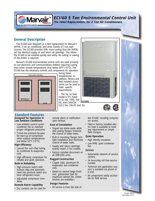
<strong>ECU60</strong> 5 <strong>Ton</strong> <strong>Environmental</strong> <strong>Control</strong> <strong>Unit</strong><br />
The Ideal Replacement for 3 <strong>Ton</strong> Air Conditioners<br />
General Description<br />
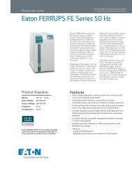
The <strong>ECU60</strong> was designed as a field replacement for Marvair’s<br />
AVP36, 3 ton air conditioner, and other brands of 3 ton wallmounts.<br />
The <strong>ECU60</strong> provides 50% more cooling than the AVP36,<br />
yet has identical supply air and return air openings. This allows<br />
the <strong>ECU60</strong> to be installed quickly and easily. No cutting or sawing<br />
of the shelter is required.<br />
Marvair’s <strong>ECU60</strong> environmental control units are used primarily<br />
to cool electronic and communications shelters requiring cooling<br />
even when outside temperatures drop below 60°F (15°C). The<br />
<strong>ECU60</strong> has the necessary controls and components for operation<br />
during these<br />
Exterior Wall of Building<br />
temperatures. In<br />
addition, factory and<br />
field installed accessories<br />
can be used to<br />
meet specific<br />
requirements.<br />
Standard 3 <strong>Ton</strong><br />
Air Conditioner<br />
<strong>ECU60</strong><br />
The 1ø, no heat<br />
model is ETL listed<br />
to UL Std. 1995, 2nd<br />
<strong>ECU60</strong><br />
Ed., and CAN/CSA -<br />
C22.2 No. 236-95 2nd. Ed.<br />
Standard Features<br />
Designed for Operation in<br />
Low Ambient Conditions<br />
• Low ambient control cycles<br />
condenser fan to maintain<br />
proper refrigerant pressures.<br />
• Timed low pressure by-pass<br />
for start-up of compressor<br />
when outdoor temperatures<br />
are below 55°F (13°C).<br />
High Efficiency<br />
• Lanced fins and rifled tubing<br />
on condenser & evaporator<br />
coils.<br />
• High efficiency compressor for<br />
reliable and quiet operation.<br />
Built-in Reliability<br />
• High pressure switch with<br />
lockout relay and automatic<br />
reset low pressure switch protects<br />
refrigerant circuit.<br />
• Adjustable compressor time<br />
delay.<br />
Remote Alarm Capability<br />
• Dry contacts can be used for<br />
remote alarm or notification<br />
upon lockout.<br />
Ease of Installation<br />
• Sloped top sheds water while<br />
side sealing flanges minimize<br />
the chance of water leaks.<br />
• Built-in mounting flanges facilitate<br />
installation and minimizes<br />
chance of water leaks.<br />
• Supply and return openings<br />
exactly match 3 <strong>Ton</strong> models.<br />
• Factory installed disconnect on<br />
all 208/230v units.<br />
Rugged Construction<br />
• Copper tube, aluminum fin<br />
evaporator and condenser<br />
coils.<br />
• Baked on neutral beige finish<br />
over galvanneal steel for<br />
maximum cabi<strong>net</strong> life. (Other<br />
finishes are available.)<br />
Design Features<br />
• All service is from the side of<br />
the <strong>ECU60</strong>, including compressor<br />
access.<br />
• Field or factory installed electric<br />
heat is available to meet<br />
any requirement or simple<br />
field changes.<br />
Quiet Operation<br />
• High density insulation.<br />
• Low RPM, quiet condenser<br />
fan.<br />
Service<br />
• Nationwide <strong>net</strong>work of service<br />
centers.<br />
• 24 hours/day toll free service<br />
number.<br />
• Technical and application support<br />
is available via phone or<br />
e-mail.<br />
• All components easily accessible<br />
for field service.<br />
<strong>ECU60</strong>, 4/02-3<br />
supersedes 2/01-2
Options<br />
The <strong>ECU60</strong> is designed and built to stringent requirements<br />
of the communications/ electronic shelter. Applications occur<br />
that have special requirements. Numerous options are<br />
available for the <strong>ECU60</strong> that meet these special needs.<br />
Hard Start Kit<br />
Used on single phase equipment to give the compressor<br />
higher starting torque under low voltage conditions. (Field<br />
installed only)<br />
Desert Duty Kit<br />
Sealed bearing condenser fan motor and special controls to<br />
allow improved operation in desert environments and<br />
ambients up to 130°F (54°C).<br />
Dehumidification<br />
Humidity controller overrides thermostat and allows electric<br />
heat to operate simultaneously with cooling. See Dehumidification<br />
Application Bulletin for details.<br />
Coastal Environment Package<br />
Extends life of unit when units are to be installed near an<br />
ocean or sea. Includes coated condenser coil, sealed ball<br />
bearing fan motor, stainless steel fasteners, sealed control<br />
panel and protective coating on copper tubing in the<br />
condenser compartment.<br />
Stainless Steel Cabi<strong>net</strong><br />
All exterior sheet metal constructed of stainless steel.<br />
Hot Gas By-pass<br />
Used in specialty applications; i.e., Mag<strong>net</strong>ic Resonance<br />
Imaging (MRI) buildings, to prevent mag<strong>net</strong>ic voltage<br />
disturbance caused by compressor cycling. Hot gas<br />
by-pass option packages are available to allow operation<br />
to 20°F (-7°C). Please refer to Hot Gas By-pass Application<br />
Bulletin for details.<br />
Color<br />
The standard cabi<strong>net</strong> color is Marvair’s driftwood beige. Other<br />
colors include arctic white, silver grey and desert brown.<br />
Contact your representative or the factory for color chips.<br />
Protective Coil Coatings<br />
Either the condenser coil or evaporator coil or both can be<br />
coated with a protective coating. Used in corrosive or marine<br />
environments such as power plants, paper mills, and applications<br />
susceptible to salt-spray. Note: Cooling capacity of<br />
units with coated coil(s) may be reduced by up to 5%.<br />
Grilles<br />
Supply grille.<br />
28” x 8” (711 mm x 203 mm) P/N 80675<br />
Return air filter grille. (Required)<br />
28” x 14” (711 mm x 356 mm) P/N 80672<br />
<strong>Control</strong>lers, Thermostats and Sub-Bases<br />
CommStat3 Microprocessor <strong>Control</strong>ler P/N S/04581<br />
Solid state controller designed to operate a fully or partially<br />
redundant air conditioning system. Insures equal wear on<br />
both air conditioners while allowing the lag unit to assist<br />
upon demand. Lead/ lag changeover is factory set at 7 days,<br />
but is field programmable in 1/2 day increments from 1/2 to<br />
7 days. The CommStat 3 <strong>Control</strong>ler has LED's to indicate<br />
status & function, digital display of temperature, a comfort<br />
override button for energy savings, five alarm relays, a built<br />
in temperature sensor and is fully programmable. See<br />
CommStat 3 <strong>Control</strong>ler Product Data Sheet for details on<br />
operation & installation.<br />
LL357A1 Lead/Lag <strong>Control</strong>ler<br />
Two stage heat and cool thermostat with solid state module<br />
for redundant operation with adjustable (2°-12°F (1.1° -<br />
6.7°C)) interstage differential. (See the LL357A1 Product<br />
Data Sheet for details.)<br />
Thermostat P/N 50071<br />
One stage cool and one stage heat.<br />
Thermostat P/N 50059<br />
Two stage cool and two stage heat.<br />
Note: Either sub-base can be used with either thermostat.<br />
Sub-Base P/N 50072<br />
Fan: Auto and on. System: Auto and on.<br />
Sub-Base P/N 50062<br />
No fan switch. System: Auto and on. Note: 50062 requires a<br />
field installed jumper for proper operation.<br />
Model Identification<br />
ECU 60 AC<br />
• •<br />
N<br />
Nominal Cooling<br />
Capacity<br />
60,000 BTUH<br />
Air Conditioner<br />
Power Supply<br />
A = 208/230V,1ø,60Hz<br />
C = 208/240V,3ø,60Hz<br />
D = 460V,3ø,60Hz<br />
Configuration<br />
N = Non economizer<br />
<strong>ECU60</strong>, 4/02-3<br />
<strong>Environmental</strong><br />
<strong>Control</strong><br />
<strong>Unit</strong><br />
2<br />
Electric Heat – kW<br />
00 09<br />
05 10<br />
15
Summary Ratings (Wire Sizing)<br />
00 = None 05 = 5 kw 09 = 9kw 10 = 10kw 15 = 15 kw<br />
MODEL/ CIRCUIT #1 CIRCUIT #1 CIRCUIT #1 CIRCUIT #1 CIRCUIT #1 CIRCUIT #2<br />
SUFFIX MCA MFS MCA MFS MCA MFS MCA MFS MCA MFS MCA MFS<br />
<strong>ECU60</strong>/A 40 60 40 60 – 59 60 40 60 52 60<br />
<strong>ECU60</strong>/C 28 40 – 34 40 – 52 60 –<br />
<strong>ECU60</strong>/D 15 20 – 17 20 – 26 30 –<br />
The above chart should be used as a general guideline for estimating conductor size and overcurrent protection for the unit<br />
models listed. For specific requirements, refer to the data label attached to the unit cabi<strong>net</strong>.<br />
MCA = Minimum Circuit Ampacity (Wiring Size Amps) MFS = Maximum External Fuse or External HACR Circuit Breaker Size.<br />
Efficiency and Capacity Ratings*<br />
MODEL 60A 60C 60D<br />
COOLING BTUH 53,000 53,000 53,000<br />
RATED CFM 1840 1840 1840<br />
ESP 0.20 0.20 0.20<br />
*@ 95°F outdoor and 80°F DB and 67°F WB indoor.<br />
Note: All performance and capacity ratings are for a 60 Hz power supply.<br />
Ratings are also affected by altitude.<br />
Electrical Characteristics<br />
BASIC COMPRESSOR OUTDOOR FAN MOTOR INDOOR FAN MOTOR<br />
MODEL VOLTS Hz/Ph RLA LRA MCC VOLTS Hz/Ph RPM FLA HP VOLTS Hz/Ph RPM FLA HP<br />
<strong>ECU60</strong>A 208/230 60/1 25.64 135.0 40.0 208/230 60/1 825 2.8 1/3 208/230 60/1 1075 5.2 1/2<br />
<strong>ECU60</strong>C 208/230 60/3 16.0 137.0 24.0 208/230 60/1 825 2.8 1/3 208/230 60/1 1075 5.2 1/2<br />
<strong>ECU60</strong>D 460 60/3 8.97 69.0 14.0 208/230 60/1 825 2.8 1/3 208/230 60/1 1075 5.2 1/2<br />
RLA = Rated Load Amps LRA = Locked Rotor Amps MCC = Maximum Continuous Current FLA = Full Load Amps<br />
<strong>Unit</strong> Load Amps<br />
BASIC MODEL COOLING LOAD OF RESISTIVE HEATING ELEMENTS ONLY (IN AMPS) TOTAL HEATING AMPS (MAX.)<br />
AMPS (MAX.) 05 KW 09 KW 10 KW 15 KW+ 05KW 09KW 10KW 15KW+<br />
<strong>ECU60</strong>A• 34 21 – 42 63 26 – 47 68<br />
<strong>ECU60</strong>C• 24 – 22 – 36 – 27 – 41<br />
<strong>ECU60</strong>D••• 17 – 11 – 18 – 16 – 23<br />
•Heating kW shown for 240V. Derate heat output by 25% for 208V service. + Total heating amps for ALL 1ø units with 15kW includes both circuits (#1 and #2)<br />
•••Heater kW shown for 480V.<br />
NOTE: Three phase equipment contains single-phase motor loads. Values shown are maximum phase loads. Loads are not equally balanced on each phase. Total cooling and total heating<br />
amps include motor loads.<br />
Sensible/Total Ratio @95°F<br />
(35°C) Outside Air DB<br />
MODEL<br />
<strong>ECU60</strong><br />
TOTAL CAPACITY 53,000<br />
SENSIBLE HEAT RATIO 0.75<br />
SENSIBLE CAPACITY 39.700<br />
Sensible ratios based on ARI Standard 210 Indoor<br />
Conditions of 80°F (27°C) WB indoor.<br />
CFM @ ESP (Wet Coil)<br />
MODEL 0.10 0.20 0.30<br />
<strong>ECU60</strong> ––– 1900 1760<br />
Ship Weight<br />
MODEL<br />
<strong>ECU60</strong><br />
LBS/KG<br />
<strong>ECU60</strong> 535/245<br />
3 <strong>ECU60</strong>, 4/02-3
TM<br />
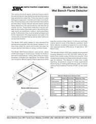
Dimensional Data – <strong>ECU60</strong><br />
MODEL A B C D E F G H I J K L M N O P Q<br />
60 (inches) 45 22-5/8 86 8 18 14 42-1/2 28 1-5/16 40-9/16 38-9/16 1-1/8 43-1/8 42-3/16 40-1/2 2-1/4 83-5/16<br />
60 (mm) 1143 575 2184 203 457 356 1080 711 33 1030 980 29 1095 1072 1029 57 2116<br />
NOTE: Dimensional tolerance ± 1/16” (2 mm)<br />
A<br />
B<br />
L<br />
2.00<br />
M<br />
MOUNTING HOLES CTR. TO CTR.<br />
3/8" SQ (10 PLC'S)<br />
D<br />
H<br />
SUPPLY AIR DUCT<br />
HEATER<br />
ACCESS<br />
COVER<br />
E<br />
E<br />
C<br />
BREAKER<br />
ACCESS<br />
COVER<br />
Q<br />
I<br />
3/4" X 1"<br />
ELECTRICAL<br />
K.O.'S<br />
F<br />
P<br />
H<br />
RETURN AIR DUCT<br />
P<br />
81.50<br />
FRESH AIR HOOD<br />
65.25<br />
AIR<br />
OUTLET<br />
J<br />
2<br />
K<br />
AIR<br />
INLET<br />
G<br />
N O<br />
3/4" X 1"<br />
ELECTRICAL K.O.'S<br />
16.50<br />
32.75<br />
49.00<br />
3/4"I.D.<br />
DRAIN<br />
1.5 FLANGE WIDTH<br />
FRONT VIEW<br />
R.H. SIDE VIEW<br />
BACK VIEW<br />
4-3/4”<br />
(121 mm)<br />
3-7/8” (98 mm) 19-3/4”<br />
(502 mm)<br />
1-5/8” (41 mm)<br />
41” (1041 mm)<br />
19-3/4”<br />
(502 mm)<br />
BOTTOM MTG. BRKT.<br />
W/MTG. HOLE LOCATIONS<br />
3/8” (10 mm)<br />
(6 PLC'S)<br />
Complete installation instructions are in the ComPac I & II A/C Manual. Detailed dimensional data available upon request. A complete warranty statement can be<br />
found in each product’s Installation/Operation Manual, on our website at www.marvair.com or by contacting Marvair at 229-273-3636. As part of Marvair’s continuous<br />
improvement program, specifications are subject to change without notice.<br />
TM<br />
P.O. Box 400 • Cordele, GA 31010<br />
156 Seedling Drive • Cordele, GA 31015<br />
Ph: 229-273-3636 • Fax: 229-273-5154<br />
Email: marvair@airxcel.com • Inter<strong>net</strong>: www.marvair.com<br />
<strong>ECU60</strong>, 4/02-3<br />
4