Memristor-The Missing Circuit Element - IEEE Global History Network
Memristor-The Missing Circuit Element - IEEE Global History Network
Memristor-The Missing Circuit Element - IEEE Global History Network

Create successful ePaper yourself
Turn your PDF publications into a flip-book with our unique Google optimized e-Paper software.
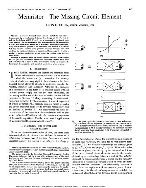
<strong>IEEE</strong> ,EEE TRANSAcrlONS TRANSACTIONS ON CIRCUIT THEORY, VOL. cr-18, CT-18, No.5, NO. SEPTEMBER 1971 507<br />
<strong>Memristor</strong>-<strong>The</strong> <strong>Missing</strong> <strong>Circuit</strong> <strong>Element</strong><br />
LEON O. 0. CHUA, SENIOR MEMBER, <strong>IEEE</strong><br />
Abstract-A new two-terminal circuit element-called the memrirtor- memrislorcharacterized<br />
by a<br />
relationship between the charge q(I} q(t) == s f'-'" St% i(r} i(7J dr d7<br />
and the flux-linkage I~------:"<br />
i<br />
+<br />
i<br />
+<br />
(a)<br />
(b)<br />
(c) (cl<br />
(d) Cd)<br />
Fig. 1.<br />
Proposed symbol for memristor and its three basic realizations.<br />
(a) <strong>Memristor</strong> and its qrq q-q curve. (b) <strong>Memristor</strong> basic realization I: 1:<br />
M-R mutator terminated by nonlinear resistor CR. &t. (c) <strong>Memristor</strong><br />
basic realization 2: M-L mutator terminated by nonlinear inductor<br />
.c. C. (d) <strong>Memristor</strong> basic realization 3: M-C mutator terminated by<br />
nonlinear capacitor e.<br />
and theflux-linkage<br />
'P. cp. Out of the six possible combinations<br />
of these four variables, five have led to well-known relationships<br />
[I]. [l]. Two of these relationships are already given<br />
by q(t)=J~ q(t)=JL .. w i(T) dTd 7 and «J(t)= cp(t)=sf. J~ .. m v(T) D(T) dT. d7. Three other rela<br />
rela-<br />
relationships<br />
are given, respectively,. by the axiomatic definition<br />
of the three classical circuit elements, namely, the resistor<br />
(defined by a relationship between v and i), the inductor<br />
(defined by a relationship between 'P cp and i), and the capacitor<br />
(defined by a relationship between q and v). Only one relationship<br />
remains undefined, the relationship between 'P 9<br />
relaand<br />
q. From the logical as well as axiomatic points of view,<br />
it is necessary for the sake of completeness to postulate the<br />
existence ofa a fourth basic two-terminal circuit element which<br />
R<br />
I.<br />
(<br />
Authorized licensed use limited to: <strong>IEEE</strong> Publications Staff. Downloaded on December 4, 2008 at 14:12 from <strong>IEEE</strong> Xplore. Restrictions apply.
508 <strong>IEEE</strong> TRANSACTIONS ON CIRCUIT THEORY, SEPTEMBER 1971<br />
508<br />
<strong>IEEE</strong> TRANSACTIONS ON CIRCUIT THEORY, SEPTEMBER 1971<br />
=<br />
TABLEI<br />
I<br />
CHARACTERIZATION CHARACTERIZATIONAND ANDREALIZATION REALIZATIONOF OFM-R, M-L, M-L, AND ANDM-C M-CMUTATORS<br />
MUTATORS<br />
[~:] [ T(P)] ~::]<br />
TRANSMISSION<br />
MATRIX MATRIX<br />
SYMBOL<br />
BASH: BASIC<br />
REALIZATIONS<br />
TYPE<br />
‘PE<br />
AND<br />
"<br />
::I = [T(P’][J<br />
USING CONTROLLED CHARACTERIZATION<br />
CHARACTERIZATION<br />
SOURCES<br />
I<br />
d£te<br />
REALIZATION I I REALIZATION 22<br />
w+gf<br />
D---a<br />
‘2<br />
F--ail<br />
il<br />
+<br />
[ 1<br />
(2) + i2+<br />
R<br />
+(!%) -i2+<br />
~ ~; “2<br />
P 0<br />
+<br />
+<br />
I<br />
I ~R,b) = “2 I c<br />
“2<br />
0 P<br />
Uqdt) -<br />
(li,dt)<br />
dVp<br />
“I= dt<br />
'..",{.:] I;i-[J'~') ,f~ ;i-@,:,') .f~<br />
- 1·-<br />
~ t ! ~ VI : t v 2<br />
I 0<br />
dV2<br />
I~ (/vldt) ~ ~ (/ildtl 1----4<br />
VI' dT<br />
dip di 2<br />
iI i = -7<br />
Y-R M·R<br />
l " -dT<br />
-<br />
MUTATOR MUTATOR (q.Vl -RvR,iR)<br />
REALIZATION I I REALIZATION 2<br />
~ 2 -<br />
~;<br />
2 -<br />
v, :;: ! v<br />
'.. ",{ 0<br />
2 VI ~ t v2<br />
2 P<br />
di2<br />
1';.- (/ildtl ~ ~ (/vldt) f.--4<br />
VI’ v I=--<br />
-7 dt<br />
:] l;i-~~).t \ ;i-[J~~;),{~<br />
I<br />
i I • ~ dt REALIZATION I REALIZATION 2<br />
M-L<br />
MUTATOR<br />
M-C<br />
MUTATOR<br />
II i i 2 l 1 2<br />
+ + +<br />
+<br />
(q,9?)"""'" (IL,cPLl<br />
~1'/lldt)<br />
VI<br />
gq-:<br />
~~ di 2 v<br />
LW<br />
2 v, v2<br />
)<br />
'.C ",{ ,<br />
:] - 12 -"'jjf<br />
- - .-<br />
~ ~ V; I 0<br />
I - I -<br />
REALIZATION 3 REALIZATtON REALIZATION 4<br />
VI" V<br />
(Identical to TcR,(p) TCR,( p)<br />
“I = “2 2 i l<br />
1 2<br />
i<br />
off ac Type , I CoR C-R MUTATOR)<br />
1<br />
2<br />
. di2 2 +<br />
II'-dl<br />
iI=-<br />
-<br />
2<br />
I<br />
2<br />
2 - 2 -<br />
-<br />
’ :<br />
v<br />
,"--<br />
i<br />
(/lldtl ~ .0-- (vI) -<br />
(q,~)-(jPL.iL) (q,# -WL, iL)<br />
REALIZATION I REALIZATION 2<br />
i, i 2<br />
[ 1<br />
i<br />
0 P<br />
m<br />
:<br />
TML2fP” )<br />
:]<br />
2 i, i 2<br />
.~ '.C ",{ 0 o<br />
Y<br />
di,<br />
v, = dt<br />
TLR2(p)<br />
'~R>' (v2' +<br />
- 2 - 2 I<br />
v, ~ ,~ t v2 ~~~)§""<br />
~ + ! ~<br />
_ lI 2<br />
vl dt) - (il)_<br />
VI' - dT<br />
(Identical to (p)<br />
ofmf ac Type 2 L-R MUTATOR)<br />
MUTATOA !I<br />
ii, l<br />
• =v2 v2<br />
.I<br />
REALIZATION REALIZATlON I REALIZATION 2<br />
I,<br />
~ i 2 i,<br />
~ 1 2<br />
+ + + +<br />
(q,tp) - (qc'v c )<br />
,<br />
:f-pq*<br />
[ 1<br />
v, (~- ) v 2 VI lIvldt-v, ) v2<br />
dt "2<br />
P 0<br />
- - -l<br />
I ;-<br />
'Me k,(P) ",{ , o (<br />
~ ~ v~ I 0<br />
I - I -<br />
I<br />
REALIZATION REALlZATlON 3 REALIZATION REALIZATlON 4<br />
• dV2 (Identical (I&tical to 10 TLRltp) ( p)<br />
VI<br />
I<br />
dt<br />
ofd a Type II L-R MUTATOR)<br />
'1<br />
~ ~<br />
i, = - i2<br />
~ :]<br />
v, =-i<br />
2<br />
(Idtmticdl t0 TCR2 ( p)<br />
. dV2 d”2<br />
of,f a Type 2 CoR C-R MUTATOR)<br />
WTATOF f)<br />
II il : =r(t Cit<br />
~[l',{~<br />
I +(!!k) i2+<br />
!TDq-y +<br />
(VI)-“!<br />
;i-@*),,~<br />
v, : t v2 VI t : v2<br />
~@~).,lE i 2<br />
L 1<br />
~@", ..f<br />
i2<br />
i," - 1 2<br />
v, : t v 2<br />
v t + v 2<br />
(q .'!') -(vc,qc)<br />
~ (i,) ~ (/Vldt)-<br />
~<br />
i l<br />
i2<br />
r. ,- il i2<br />
blcp=<br />
~ '.c,"'{: p o 3pq<br />
“2<br />
1 ~]<br />
v, • - i<br />
- (VI)<br />
2 (Identical to TCR2 (p) r---4 ~<br />
REALIZATION II<br />
REALIZATION 2<br />
-D---a<br />
'I '2 II<br />
[Jr.)"t<br />
12<br />
+<br />
(ipI<br />
+<br />
v, “I ;<br />
vx<br />
2 VI v2<br />
+: (/ll<br />
t/ildt)-<br />
):<br />
I<br />
I----i<br />
r+-<br />
~" ,,;t r-"+ ~ ~<br />
+<br />
Authorized licensed use limited to: <strong>IEEE</strong> Publications Staff. Downloaded on December 4, 2008 at 14:12 from <strong>IEEE</strong> Xplore. Restrictions apply.
CHUA: MEMRISTOR-MISSING CIRCUIT ELEMENT 509<br />
r-------------,....----~--~---o+Ecc<br />
l?&l50)<br />
RJ9lO)<br />
Q014<br />
I 4<br />
R4( IOOK)<br />
(2N4236)<br />
(2~4236) L<br />
+Ecc<br />
+<br />
~j=<br />
I f I 1 1 h-b--&<br />
Port I Port 2<br />
1 AR, 1 SO-IOA JRLq-<br />
4-<br />
iZ +<br />
- k +<br />
1<br />
“2<br />
-<br />
l~Z-<br />
I I I<br />
'------------------........---.4---Ecc<br />
’ *-kc<br />
Fig. 2. Practical active circuit realization of type-! type-l M-R mutator based on realization! 1 of Table I.<br />
is characterized by a
510 <strong>IEEE</strong> TRANSACfIONS TRANSACTIONS ON CIRCUIT THEORY, SEPTEMBER 1971<br />
r-----I+<br />
to-E<br />
'- ~M202 >-.......--,<br />
+E<br />
~<br />
E -E<br />
'--<br />
LM202 ~--~-- <br />
~+<br />
R I2<br />
(IK Pot)<br />
+E<br />
R I7<br />
(IOK.I~)<br />
I8<br />
R<br />
__.......-i{,ijR<br />
I4<br />
+E<br />
(IOK.I~)<br />
L<br />
..---- 10 + horizontal hwlZOontol<br />
to l<br />
lerminal twmiml of Of<br />
alcilloscope<br />
ouilloscop*<br />
t<br />
NEXUS<br />
IO-A '>--+~-~P----R-ll---"""'-'----lf---+--+ I<br />
+ t<br />
22+E v.(II=k.!v(TldT<br />
v,( I= k, jvbldr<br />
R 5<br />
_ -CD<br />
l?r+<br />
--(D<br />
'<br />
...---''--1- 1<br />
R~ -E NEXUS<br />
OOK.I~) SOIO-A -=<br />
-==- ...<br />
(IOK.I~)<br />
-E<br />
-E<br />
R 24<br />
(20KPat) +E<br />
R23 (22 Meg.l<br />
L...--. I ta to ground<br />
lerminal terminal at d<br />
olei1I0icope<br />
oscilbscom<br />
R2/(IOOKl<br />
R201300Kl<br />
R 4<br />
Seriel<br />
Resillance<br />
Cli ±C3<br />
R<br />
T I R2 I (Sla;;cor A-3801l<br />
,>OOO!<br />
WindillQ<br />
Cenler<br />
500Sl<br />
R I R 2<br />
Tap Winding'<br />
R 3<br />
3.300n<br />
WindillQ<br />
-.<br />
+<br />
v,(t) vI(I)<br />
10 to<br />
‘sine lin.<br />
*IO”8 wave<br />
VoltogI voltoge<br />
gonratot ge_alar<br />
~<br />
c4tl C2<br />
PARAMETER IAMETER SPECIFICAT0NS<br />
SPECIFICATIONS<br />
R, .R2(l/Oltage-divider resillorl.<br />
see le.11.<br />
(current (currenl sensing .....ing ruustor. resislor. i;p~cal iyPical<br />
value: volue' I, 1.10. I), loo, 100, or ooon 1OO0n ). ),<br />
( series resiSlor. ta be chosen<br />
by user as il depends on the<br />
IIOllage amplitude of Ihe<br />
sine-wave Qenerator),<br />
~. qgbca* Rglscale factor foelar for mtegmtof, inlegralor,<br />
should Ihould be ot at b+t least 5K). 5K),<br />
~, R12 R I2 .• R,s R I3<br />
(I (I K wtenttomelsr polentiomeler for<br />
offset offseladjustment adjuslment for<br />
LM202 lM 202 OP AMPI.<br />
I.<br />
R7' R~s RIB ,R22 •R 22<br />
(trmwnmg (trimmingieststor relislorfor<br />
NEXUS SO-IOA SO-lOA OP AMP,<br />
typtool Iypical voluo: value, 20K). 20Kl.<br />
C I ,C2 cp .c3.cg ,C (nsutrollzotlon<br />
3<br />
,C 4 (neulrallzallon<br />
capocltors. capacitors, sea ,.. te*t text) 1<br />
C , CT C ( factor Integrator,<br />
5 7<br />
(scale foclor for inlegralor,<br />
seetmt1.<br />
1..1),<br />
R S<br />
OK Pol,)<br />
+E<br />
-E<br />
R e (100K)<br />
NEXUS<br />
SQIO-A<br />
+<br />
-E<br />
All<br />
(20K Pot) +E<br />
R IO<br />
(22Meg.)<br />
R g (300K)<br />
1<br />
I =<br />
L<br />
r<br />
I<br />
to ta + vwtlcd verlical<br />
terminal<br />
of<br />
oscillo*copr oaci1I0icope<br />
t<br />
vi{ t )*k, ]ilr)dr<br />
--o<br />
k ze!?-s<br />
X<br />
%C5<br />
to ground<br />
'-- 10 grOOM<br />
twmiml lerminalof<br />
oscilloscope oscillalcope<br />
%E (( power supply voltag.e. vollage, *% I5 15<br />
Yolts volllrtth wilhrespect reopec! to 10qound).<br />
ground),<br />
Fig. 3.<br />
Complete schematic diagramof of memristor tracerfor for tracing thepq CP-q curveof of a memristor.<br />
Authorized licensed use limited to: <strong>IEEE</strong> Publications Staff. Downloaded on December 4, 2008 at 14:12 from <strong>IEEE</strong> Xplore. Restrictions apply.
.<br />
CHUA: MEMRISTOR-MISSING CIRCUIT ELEMENT 511<br />
I<br />
q ( I) • J i( T) dT<br />
-CI)<br />
I<br />
0 p(t)?:.O and the memristor is obviously passive. To prove the<br />
converse, suppose that there exists a point qo q. such that<br />
M(qo)O e> 0 such that M(qo+.6.q)
512 <strong>IEEE</strong> TRANSACTIONS ON CIRCUIT THEORY, SEPTEMBER 1971<br />
512 <strong>IEEE</strong> TRANSACTIONS ON CIRCUIT THEORY, SEPTEMBER 1971<br />
t<br />
q(tl q.(t) -ji(TldT<br />
=ii(r)dr<br />
-CD -m<br />
t<br />
9I(tl -jv(TldT<br />
-CD<br />
(0). (a ). Simple <strong>Memristor</strong> Voltage-Divider <strong>Circuit</strong><br />
v( t I, volts<br />
i(t), mo<br />
t, 1, msec.<br />
rp, Q, milliweber<br />
milli-<br />
t,msec. t , ( b 1 Horuontal Scole:2.66 milli-weber per division,<br />
Vertical Stole: 5 p coul per division.<br />
(c( c I.Horizontol hlorizontol Scale' Scale: 2 msec. per division.<br />
Vertical Scale' Scale:5 5 mo per division (upper trocel. trace).<br />
101lOits lOvolts per division (lower trocel. trace).<br />
v( t I. volts<br />
i(t), mo<br />
'''~'~l!,,''''''':'''':'''':'-<br />
i -t -+-J - 1<br />
_+.~ ~ -+- I J-<br />
'P, p. milJiweber<br />
milli-<br />
(d ).Horizontol Mlorizontol Scale' Scala: 2.66 milli-weber per division.<br />
Vertical Scale: 5 ,. p coul per division.<br />
t, t , msec.<br />
t, msec.<br />
(e I.Horizontol LHorizontol Scale' Scale: 5 msec. per division. divisioo.<br />
Vertical Scale:2 2 mo a per division (upper tracel. tmce).<br />
5 volts volte per division (lower tracel. trace).<br />
V( t I, volts<br />
i(t I,mo<br />
. . . . ,:) . .<br />
J=~A·.····.····.·<br />
(jJ, p, milliweber<br />
milli-<br />
( f I.Horizontal Mlorizontol Scale' Scale: 2.66 milli-weber per division. division,<br />
Vertical Scale' Scale: 5,. 5 p coul per division.<br />
(g g I.Horizontal ).Horizontol Scale, Scale:5 5 msec. per division.<br />
Vertical Scole'5 Scale:5 mo per division (upper trocel. trace).<br />
5 volts wits .per division (lower trocel. trace).<br />
Fig. 5.<br />
Voltage and current waveforms associated with simple memristor circuit corresponding to a sinusoidal input<br />
signal [(c) and (e)] and a triangular input signal [(g)], r(g)], respectively.<br />
t,msec.<br />
t,msec.<br />
<strong>The</strong>orem 2: Closure <strong>The</strong>orem<br />
(Kirchhoff voltage law) equations:<br />
A one-port containing only memristors is equivalent to a<br />
memristor.<br />
Proof: If we let ij, ii, Vj, vj, qj, and 'Pj vj denote the current, voltage,<br />
charge, and flux-linkage of the jth memristor, where j= I, 1,<br />
2, 2;.., ... , b, and if we let i and v denote the port current and<br />
port voltage of the one-port, then we can write (n-I) 1) independent<br />
KCL (Kirchhoff current law) equations (assuming<br />
the network is connected); namely,<br />
inde-<br />
b<br />
cxjoi CvjOi + 2 L cxjkik ajkik = 0,<br />
j=l,2,.*.,n-1 j = 1, ... , n - 1 (6)<br />
k=l k~l<br />
@j&J + 5 PjkVk = 0, j=l,2,..., j = 1, 2, ... , b - n + 2 (7)<br />
k=l k~l<br />
where (3jk @jk is either I, 1, -I,- 1, or 0. If we integrate each equation<br />
in (6) and (7) with respect to time and then substitute<br />
'Pk ‘pk = 'Pk(qk) (pk(qk) for 'Pk pk in the resulting expressions,? expressions,7 we obtain<br />
b<br />
& L CXjkqk ffjk@ = Qj -<br />
CXjoq, ffjoPt j=l,2,***,n-1 j = 1, ... , n - 1 (8)<br />
k=l<br />
PjOCp + f: pjk(pk(qk) = *j, j = 1, 27 ’ ’ . , b - n + 2 (9)<br />
k=l kzl<br />
b<br />
{3jOV + L {3jkVk = 0,<br />
b<br />
(6) {3jO'P + L (3jk'Pk(qk) = j, j = 1,2, ... , b - n + 2 (9)<br />
where CXjk ajk is either I, 1, -I,- 1, or 0, b is the total number of<br />
memristors, and n is the total number of nodes. Similarly,<br />
we can write a system of (b-n+2) independent KVL<br />
7 We have assumed for simplicity that the mernristors are chargecontrolled.<br />
<strong>The</strong> proof can be easily modified to allow memristors mernristors char<br />
char-<br />
chargeacterized<br />
by arbitrary qr-q e curves.<br />
Authorized licensed use limited to: <strong>IEEE</strong> Publications Staff. Downloaded on December 4, 2008 at 14:12 from <strong>IEEE</strong> Xplore. Restrictions apply.
CHUA: MEMRISTOR-MISSING CIRCUIT ELEMENT 513<br />
513<br />
where Qi Qj and _joUQo. Following identical procedure<br />
and notation as given in [11, [ll, ch. 3], 31, we let Wwa a denote<br />
the set of independent frequencies and make a small change<br />
in ocf>a=o(wat). This<br />
pro-<br />
6~$,=Li(~,t). perturbation induces a change in the<br />
action A(t): :<br />
(14)<br />
(14)<br />
But since sintie A(q) = J&(q) fgcp(q) dq, we have<br />
oA 6A = (cp)(oq) ((p)(Sq) = [Re L: F ~~ TY c@at<br />
iwat ]<br />
[ a JWWC2 a 1<br />
.[Re L: c 5 I a (awajawa)Ciwatocf>a]. (ao,/aw,)ej~‘h<br />
1 (15)<br />
’<br />
aLI Wa al<br />
Equating (14) and (15) and taking their time averages, we<br />
obtain the following Manley-Rowe-like formula relating the<br />
. ~ _1<br />
reactwe reactive powers P,=+ Pa=2" I<br />
Im m (V,Z,*): a<br />
1*)' a .<br />
~[ac&/awa] [P&a = 0 .<br />
(16)<br />
(16)<br />
P<br />
a<br />
Authorized licensed use limited to: <strong>IEEE</strong> Publications Staff. Downloaded on December 4, 2008 at 14:12 from <strong>IEEE</strong> Xplore. Restrictions apply.
Authorized licensed use limited to: <strong>IEEE</strong> Publications Staff. Downloaded on December 4, 2008 at 14:12 from <strong>IEEE</strong> Xplore. Restrictions apply.<br />
514 <strong>IEEE</strong> TRANSACTIONS ON CIRCUIT THEORY, SEPTEMBER 1971<br />
It is possible to derive a Page-Pantell-like inequality re- relating<br />
the realpowers of a passive memristor by making use<br />
of the passivity criterion (&)(64)>0 (ocp)(oq)'?°(<strong>The</strong>orem (<strong>The</strong>orem 1); namely,<br />
L<br />
where Pa=3 Pa== t Re (Val:) VaZz) is the real power at frequency w,. wa.<br />
Since the procedure for deriving (17) follows again mutatis<br />
mutandis that given by Penfield [11], 111, it will not be given here<br />
to conserve space. An examination of (17) shows that gain<br />
proportional to the frequency squared is likely in a mem- memristor<br />
upconverter, but that severe loss is to be expected in<br />
a memristor mixer. It is also easy to show that converting<br />
efficiencies approaching 100 percent may be possible in a<br />
memristor harmonic generator.<br />
So far we have considered only pure memristor networks.<br />
Let us now consider the general case of a network containing<br />
resistors, inductors, capacitors, and memristors. <strong>The</strong> equa- equations<br />
of motion for this class of networks now take the form<br />
of a system of m first-order nonlinear differential equations<br />
in the normal form $=f(x, x=f(x, t) [I], [l], where x is an mX 1 vector<br />
whose components are the state variables. <strong>The</strong> number m is<br />
called the “order "order of complexity” complexity" of the network and is equal<br />
to the maximum number of independent initial conditions<br />
that can be arbitrarily specified [1]. [I]. <strong>The</strong> following theorem<br />
shows how the order of complexity can be determined by<br />
inspection.<br />
<strong>The</strong>orem 5: Order of Complexity<br />
Let N be a network containing resistors, inductors, capacitors,<br />
memristors, independent voltage sources, and inde<br />
inde-<br />
pendent current sources. <strong>The</strong>n the order of complexity m of<br />
N is given capaciby<br />
I<br />
(17)<br />
-1<br />
(18)<br />
state variables occurs whenever an independent loop con- consisting<br />
of elements corresponding to those specified in the<br />
definition of IZ.&~ nM and nLw nLM is present in the network. [We as- assume<br />
the algebraic sum of charges around any loop (flux- (fluxlinkages<br />
in any cut set) is zero.] Similarly, a constraint<br />
among the state variables occms occ\:lrs whenever an independent<br />
cut set consisting of elements corresponding to those speci- specified<br />
in the definition ofnM fiM and &CM nCM is present in the network.<br />
Since each constraint removes one degree of freedom each<br />
time this situation occurs, the maximum order of complexity<br />
(bL+bc+bM) must be reduced by one.<br />
Q.E.D.<br />
IV. AN ELECTROMAGNETIC INTERPRETATION<br />
OF MEMRISTOR CHARACTERIZATION<br />
It is well known that circuit theory is a ;llimiting limiting<br />
special<br />
casg cas~<br />
of electromagnetic field theory. In particular, the char- characterization<br />
of the three classical circuit elements can be<br />
given an elegant electromagnetic ekctromagnetic interpretation in terms of<br />
the quasi-static expansion of Maxwell’s Maxwell's equations [12]. Our<br />
objective in this section is to give an analogous interpreta- interpretation<br />
for the characterization of memristors. While this<br />
interpretation does not prove the physical realizability of a<br />
“memristor "memristor device” device" without internal power supply, it does<br />
suggest the strong plausiblity that such a device might some- someday<br />
be discovqred. discovered. Let us begin by writing down Maxwell’s Maxwell's<br />
equations in differential form:<br />
curl E =<br />
aD<br />
curl H = J +-+ f8f at<br />
dB<br />
curl E = -<br />
a- Ly --<br />
(21)<br />
aT a7<br />
where bL br. is the total number of inductors; bc is the total<br />
number of capacitors; b,ll M is the total number of memristors;<br />
aD<br />
curl H = J + a! $<br />
(?a<br />
nM nnl is the number of independent loops containing only<br />
(22)<br />
aT<br />
memristors; liCE /?CE is the number of independent loops containing<br />
only capacitors and voltage sources; 11 nL.ll LM is the<br />
where E, H, D, B, and J are functions of not only the posi<br />
posi-<br />
connumber<br />
of independent loops containing only<br />
inductors<br />
and memristors; ;nM h,,r is the number of independent cut sets<br />
containing only memristors;nLJ fiLJ is the number of independent<br />
cut sets containing only inductors and current<br />
sources; flCM ric.nr is the number of independent cut sets con<br />
con-<br />
indetion<br />
(x, y, z), but also of a(Y and T. 7. If we were to expand these<br />
vector quantities as aformala power series in acy and substitute<br />
them into (21) and (22), we would obtain upon equating the<br />
coefficients coeficients of an, CP, the nth-order Maxwell's Maxwell’s equatiol1s, equaiions, where<br />
n=O, 1,2, .... ’ . . .<br />
taining only capacitors arid and memristors. .<br />
Many electromagnetic phenomena and systems can be<br />
Proof: ProCf: It is well known that the order of complexity of an<br />
satisfactorily analyzed by using only the zero-order and firstorder<br />
first-<br />
RLC network is given by m~(bL+bc)-l1cE-fzLJ<br />
m=(bL+bc)-IzCE-YiLJ [IJ. [l]. It<br />
Maxwell's Maxwell’s equations; the corresponding solutions are<br />
follows, therefore, from (1)-(4) (l)-(4) that for an RLC-memristor<br />
called quasi-staticfields. It has been shown that circuit theory<br />
network with I1 n, m =nLM=ii,l/=fi= nLlll = i?,,, = i2c.1, cJ1 =0, =O, each nlemristor niemristor belongs to the realm of quasi-static fields and can be studied<br />
introduces a new state variable and we have m=(bl.+bc<br />
m=(b,,+bc with the help of<br />
r the<br />
.<br />
following Maxwell's Maxwell’s equations in quasistatic<br />
form [12].<br />
quasi-<br />
+bM)-ncE-nLJ. +b,+i)--ncg-CiLJ. Observe next that a constraint among the<br />
1121.<br />
aB<br />
at<br />
(19) 09)<br />
(20)<br />
where E and H are the electric and magnetic field intensity,<br />
D and B are the electric and magnetic flux density, and J<br />
is the current density. We will follow the approach presented<br />
in [12][ 121 by defining a "family “family time" time” T=cd, r=at, where a is called<br />
the "time-rate “time-rate parameter." parameter.” In terms of the new variable T,<br />
Maxwell's Maxwell’s equations become<br />
aB
CHUA: MEMRISTOR-MISSING CIRCUIT ELEMENT 515<br />
Zero-Order Maxwell’s Maxwell's Equations<br />
curl Eo EIJ = 0<br />
where .§J('), 3( .), (B( (R(.), and D(-) a)( .) are one-to-one continuous functions<br />
from R3 onto R3. Under these assumptions, (26) and<br />
(23)<br />
func-<br />
(23) (27) can be combined to give<br />
curl Ho o = Jo.<br />
(24)<br />
First-Order Maxwell’s Maxwell's Equations<br />
curl HI = d(E1). (30)<br />
Observe that (30) does not contain any time derivative.<br />
aBo<br />
(25)<br />
Hence, hence, under any specified boundary condition con,dition appropriate<br />
cur1 E1 = - a, aT<br />
for the device, the first-order electric field E1 1 is related to<br />
aDo<br />
the first-order magnetic field HI dy by a functional relation;<br />
;<br />
aoo<br />
curl HI = II J1 +--. -I- -. (26) cw namely<br />
a7<br />
aT<br />
<strong>The</strong> total quasi-static vector quantities are obtained by keeping<br />
keep-<br />
EI = f(H,). (31)<br />
only oniy the first two terms of the formal pdwer power series and atid Oy by If we substitute (31) for E1 1 in (29) and then substitute the in<br />
in-<br />
setting a= CY= I; 1; namely, E~Eo+EI, E-Eo+E1, H~Ho+HI, H=H”+Hl, D~bo+DI'<br />
D=&+D1, verse function of (B( CR( .) from (28) into the resulting expression,<br />
we obtain<br />
have been identified as electromagnetic systems whose solu<br />
solu-<br />
expres-<br />
B= B~Bo+BI, Bo+ B1, J-Jo+ J~Jo+lI. JI. <strong>The</strong> three classical circuit elements<br />
tions correspond to certain combinations of the zero-order<br />
D1 = a, o f o [W(B1)] = g(B1). (32)<br />
and first-order solutions of (23)--(26). (23)
516 1EEETRANSACTIONSON <strong>IEEE</strong> TRANsACnONS ON CIRCUITTHEORY,SEPTEMBER THEORY, SEPTEMBER 1971<br />
RI<br />
i +<br />
+<br />
” T<br />
v*( t 1 i “0<br />
i<br />
I<br />
v*( t )<br />
I----'1<br />
IO).<br />
Rz<br />
l-<br />
E ---..,..-------:<br />
v,(t)<br />
E,<br />
I<br />
---_<br />
T<br />
------_______<br />
-l<br />
by<br />
dq/dt = u&V[RI<br />
+ Rz + M(q)].<br />
Since the variables are separable, the solution is readily found<br />
to be<br />
where<br />
dq/dt = v.(t)/[RI + R 2 + M(q)]. (33)<br />
q(t) = h- l 0 (Jot v.(r) dr + «'(q(to») (34)<br />
I h(q) = 6% + R& + u?(q) I<br />
(35)<br />
and cp
CHUA: MEMRISTOR-MISSING CIRCUIT ELEMENT 517<br />
q<br />
1<br />
IIOP.·W3·~3<br />
IoP.·W2·~<br />
041 0<br />
518 <strong>IEEE</strong> TRANSACTIONS ON CIRCUIT THEORY, SEPTEMBER 1971<br />
I<br />
~-------------,<br />
+<br />
0-- --'<br />
Zener breakdown vallage: voltage : E, = + l!.zE •, E~=E,=E~=AE Z • E • t>.E<br />
3 4 R, =R2 =R3 =R4 =R3 = +<br />
(01.<br />
5G 8<br />
9<br />
------------.-::::>F-+*r-+--+----+-~ V<br />
2<br />
(b).<br />
(e).<br />
v,(I I<br />
r------,---------------i'=E~--...--------------r_--~<br />
o<br />
0 -t<br />
4<br />
-----!--------------'-------l:--E:.-----------'--_~<br />
-._____ -----__<br />
(d). Cd).<br />
, :'<br />
L.--_<br />
.-- I 1-------------:-<br />
, ,<br />
---------:~~~! i-------------i---------- !<br />
------ ------------- ------ -~-~~~ -~==~~~~-~---~~~~~==----<br />
-------- -------------i--<br />
(el.<br />
Fig. 9.<br />
Nine-segment memristor can be used to generate ten-step staircase periodic waveform.<br />
used in many instruments such as the sampling oscilloscope<br />
and the transistor curve tracer.<br />
To simplify discussion, let us consider the design ofa a fourstep<br />
staircase waveform generator. <strong>The</strong> output voltage wave<br />
wave-<br />
fourform<br />
shown in Fig. 7(d) suggests that a four-step staircase<br />
waveform can be generated by driving the circuit in Fig.<br />
7(a) with a symmetrical square wave, provided that a<br />
memristor with the 'f'-q cp-q curve shown in Fig. 7(b) is available.<br />
This memristor can be synthesized by the methods presented<br />
in Section U. II. In fact, a simple realization is shown in Fig.<br />
8(a) with a nonlinear resistor (R @ connected across port 2 of<br />
a type-2 M-.R M-R mutator. This nonlinear resistor is, in turn,<br />
realized by two back-to-back series Zener diodes in parallel<br />
with a linear resistor and has a V-I curve as shown in Fig.<br />
8(b). To obtain the desired
CHUA: MEMRISTOR-MISSING CIRCUIT ELEMENT<br />
VI. CONCLUDING REMARKS<br />
VI. CONCLUDING REMARKS<br />
<strong>The</strong> memristor has been introduced as the fourth basic.<br />
circuit element. Three new types ofmutators have been introduced<br />
for realizing memristors in the form of active circuits.<br />
An appropriate cascade connection of these mutators and<br />
those already introduced in [3] can be used to realize higher<br />
order elements characterized by a relationship between v(m)(t) @j(t)<br />
introand<br />
i(n)(t), i@)(t), where v(m)(t) rW(t) (i(n)(t» (P(t)) denotes the mth (nth) time<br />
derivative of v(t) u(t) (i(t» (i(t)) if m>O (n>O), (n>(j), or the mth iterated<br />
time integral of v(t) u(t) (i(t» (i(t)) if m