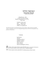
1865 Megohmmeter/IR Tester Instruction Manual - IET Labs, Inc.
1865 Megohmmeter/IR Tester Instruction Manual - IET Labs, Inc.
1865 Megohmmeter/IR Tester Instruction Manual - IET Labs, Inc.

You also want an ePaper? Increase the reach of your titles
YUMPU automatically turns print PDFs into web optimized ePapers that Google loves.
<strong>1865</strong> <strong>Megohmmeter</strong>/<strong>IR</strong> <strong>Tester</strong><br />
<strong>Instruction</strong> <strong>Manual</strong><br />
Form 150073/D5<br />
©QuadTech, <strong>Inc</strong>., 1992<br />
5 Clock Tower Place, 210 East<br />
Maynard, Massachusetts, U.S.A. 01754<br />
October, 2006<br />
Telephone 978-461-2100<br />
Sales 800-253-1230<br />
Facsimile 978-461-4295<br />
Website www.quadtech.com<br />
The material in this manual is for informational purposes only and is subject to change, without<br />
notice. QuadTech assumes no responsibility for any error or for consequential damages that may<br />
result from the misinterpretation of any procedures in this publication.<br />
WARNING<br />
Potentially dangerous voltages may be present on front and rear panel terminals. Follow all<br />
warnings in this manual when operating or servicing this instrument. Dangerous energy levels<br />
may be stored in capacitors tested by this unit. Always make sure the high voltage indicator is<br />
not on when connecting or disconnecting the unknown.<br />
!<br />
Product will be marked with this symbol (ISO#3684) when it is necessary for the user to<br />
refer to the instruction manual in order to prevent injury or equipment damage.<br />
Product marked with this symbol (IEC417) indicates presence of direct current.<br />
Product will be marked with this symbol (ISO#3684) when voltages in excess of 1000V<br />
are present.
Page 2 of 87
Contents<br />
Warranty ............................................................................................................7<br />
Specifications ............................................................................................................9<br />
Accessories ............................................................................................................11<br />
Safety Precautions ...................................................................................................13<br />
Condensed Operating <strong>Instruction</strong>s ........................................................................15<br />
Introduction - Section 1<br />
1.1 Unpacking and Inspection .............................................................................21<br />
1.2 Product Overview ..........................................................................................21<br />
1.3 Controls and Indicators..................................................................................22<br />
1.3.1 Front Panel Controls and Indicators .................................................22<br />
1.3.2 Rear Panel Controls and Connectors ................................................24<br />
1.4 Installation .....................................................................................................25<br />
1.4.1 Dimensions ........................................................................................25<br />
1.4.2 Instrument Positioning.......................................................................25<br />
1.4.3 Power Requirements ..........................................................................25<br />
1.4.4 Safety Inspection................................................................................27<br />
Operation - Section 2<br />
2.1 Terms and Conventions .................................................................................29<br />
2.2 Startup ............................................................................................................29<br />
2.3 Zeroing...........................................................................................................30<br />
2.4 Connection to Device Under Test..................................................................30<br />
2.5 Measurement Procedure ................................................................................32<br />
2.5.1 General...............................................................................................32<br />
2.5.2 Default Measurement Conditions ......................................................33<br />
2.5.3 Automatic Measurement Mode..........................................................34<br />
2.5.4 <strong>Manual</strong> Measurement Mode ..............................................................36<br />
2.6 Menu Functions .............................................................................................36<br />
2.6.1 General...............................................................................................36<br />
2.6.2 Setup Menu ........................................................................................37<br />
2.6.2.1 Voltage..................................................................................37<br />
2.6.2.2 Charge Time..........................................................................38<br />
2.6.2.3 Dwell Time ...........................................................................38<br />
2.6.2.4 Measure Time .......................................................................38<br />
2.6.2.5 Discharge Time.....................................................................39<br />
2.6.2.6 Mode .....................................................................................39<br />
2.6.2.7 Range ....................................................................................40<br />
2.6.2.8 Limit......................................................................................43<br />
2.6.2.9 Stop on Pass ..........................................................................44<br />
2.6.2.10 # to Average........................................................................44<br />
Page 3 of 87
Contents (Continued)<br />
Operation - Section 2 (Continued)<br />
2.6.3 I/O Menu............................................................................................45<br />
2.6.3.1 Display Type.........................................................................45<br />
2.6.3.2 Result Format........................................................................46<br />
2.6.3.3 RS-232 ..................................................................................47<br />
2.6.3.4 IEEE-488...............................................................................48<br />
2.6.3.5 Handler..................................................................................48<br />
2.6.3.6 Results to Floppy ..................................................................48<br />
2.6.4 Utilities Menu ....................................................................................50<br />
2.6.4.1 Save Setup.............................................................................51<br />
2.6.4.2 Recall Setup ..........................................................................53<br />
2.6.4.3 Zero.......................................................................................54<br />
2.6.4.4 Lock Out ...............................................................................55<br />
2.6.4.5 Calibration ............................................................................55<br />
2.6.4.6 Set Time/Date .......................................................................56<br />
2.6.4.7 Elapsed Time ........................................................................57<br />
2.6.4.8 Calibration Date....................................................................57<br />
2.6.4.9 Set Contrast...........................................................................58<br />
2.6.4.10 LCD Backlite ......................................................................58<br />
2.7 Input/Output Interface....................................................................................58<br />
2.7.1 I/O Interface.......................................................................................58<br />
2.7.2 IEEE-488 Interface ............................................................................60<br />
2.7.3 Sample Program for National Instruments GPIB Card......................65<br />
2.7.4 Sample Program for IO Tech GPIB Card..........................................66<br />
2.7.5 RS232 Interface .................................................................................67<br />
2.7.6 Sample Program for RS232 ...............................................................68<br />
2.7.7 Results to Printer................................................................................69<br />
2.8 Error Messages ..............................................................................................70<br />
Applications - Section 3<br />
3.1 Insulation Resistance Testing ........................................................................73<br />
3.2 Test Sample Resistivity Measurements .........................................................74<br />
3.3 Capacitor Insulation Resistance.....................................................................75<br />
3.3.1 General...............................................................................................75<br />
3.3.2 Charge Time Constant .......................................................................76<br />
3.3.3 Discharge Time..................................................................................76<br />
3.4 Resistance Measurements ..............................................................................77<br />
3.5 Measurement of Voltage Coefficient.............................................................77<br />
3.6 Guarded, 3 Terminal Measurements..............................................................78<br />
Page 4 of 87
Contents (Continued)<br />
Theory Section 4<br />
4.1 General...........................................................................................................79<br />
4.2 Instrument Description ..................................................................................79<br />
4.2.1 Basic I2000 Instrument Architecture.................................................79<br />
4.2.2 <strong>1865</strong> Instrument Modules ..................................................................80<br />
4.2.3 I2000 Instrument Options ..................................................................81<br />
Maintenance/Calibration - Section 5<br />
5.1 General...........................................................................................................83<br />
5.2 Instrument Return ..........................................................................................83<br />
5.3 Routine Maintenance .....................................................................................83<br />
5.3.1 Battery Replacement..........................................................................84<br />
5.3.2 Resetting of Time and Date ...............................................................85<br />
5.3.3 Loss of Display Contrast....................................................................85<br />
5.3.4 Preventive Maintenance/Cleaning .....................................................86<br />
5.4 Calibration .....................................................................................................86<br />
5.4.1 General...............................................................................................86<br />
5.4.2 Calibration Procedure ........................................................................86<br />
Page 5 of 87
Page 6 of 87
Warranty<br />
QuadTech warrants that Products are free from defects in material and workmanship and,<br />
when properly used, will perform in accordance with QuadTech's applicable published<br />
specifications. If within one (1) year after original shipment it is found not to meet this<br />
standard, it will be repaired, or at the option of QuadTech, replaced at no charge when<br />
returned to a QuadTech service facility.<br />
Changes in the Product not approved by QuadTech shall void this warranty.<br />
QuadTech shall not be liable for any indirect, special or consequential damages,<br />
even if notice has been given of the possibility of such damages.<br />
This warranty is in lieu of all other warranties, expressed or implied, including, but<br />
not limited to any implied warranty or merchantability or fitness for a particular<br />
purpose.<br />
SERVICE POLICY<br />
QuadTech’s service policy is to maintain product repair capability for a period of at least<br />
five (5) years after original shipment and to make this capability available at the then<br />
prevailing schedule of charges.<br />
Page 7 of 87
Page 8 of 87
Specifications<br />
Resistance Range:<br />
1 x10 3 to > 1x10 14 Ω(dependent on test voltage)<br />
1x10 6 - >1x10 14 Ω at 1000VDC<br />
1x10 5 - 1x10 13 Ω at 100VDC<br />
1x10 4 - 1x10 12 Ω at 10VDC<br />
1x10 3 - 1x10 11 Ω at 1VDC<br />
(7 ranges or auto ranging)<br />
Resistance Accuracy:* ±[0.45% +{(Rx/Vx)(0.0005 FS + 2pA) + 30Ω/Rx}100%]<br />
Rx: Measured resistance in ohms<br />
Vx: Programmed voltage in volts<br />
FS: Full scale current range in amperes<br />
Voltage Range:<br />
1 to 1000, Volts programmable in two ranges<br />
Voltage Accuracy:* 1 - 100V: 1% of setting +1V<br />
25mV resolution<br />
100 - 1000V: 1% of setting +2V<br />
250mV resolution<br />
Output Voltage<br />
Impedance: 1 kΩ ± 5%<br />
Current Limited:<br />
Current Measure:<br />
< 2mA<br />
1x10 -13 to 1x10 -3 amps<br />
Current Accuracy:* 1nA to 1mA:<br />
100pA to 1nA:<br />
1pA to 100pA:<br />
±[0.5% + (0.0005FS + 2pA)]<br />
±[1% + (0.0005FS + 2pA)]<br />
±[10% + (0.0005FS + 2pA)]<br />
Input Impedance: 5 kΩ ± 5%<br />
Measure Limits:<br />
Display:<br />
Pass/Fail (1 limit)<br />
LCD graphic display<br />
Voltage warning indicator<br />
Pass/Fail indicator<br />
* specified at front panel connectors<br />
Page 9 of 87
Specifications (Continued)<br />
Test Cycle: <strong>Manual</strong>: Charge, Measure, Discharge<br />
Automatic: Charge time: 0 -300 sec<br />
Dwell time: 0 - 300 sec<br />
Measure time: 0 - 300 sec (0 – 999 on later units)<br />
Discharge time: 0 - 300 sec<br />
I/O Interface:<br />
Input Terminals:<br />
Dimensions:<br />
Weight:<br />
Environmental:<br />
Standard -RS232<br />
I/O Port (w/safety interlock)<br />
Optional -<strong>1865</strong>-01 - IEEE-488, factory installed at unit purchase<br />
<strong>1865</strong>-02 - Floppy Drive, 3.5", factory installed only<br />
<strong>1865</strong>-03 - Rear panel input terminals, factory installed at purchase<br />
<strong>1865</strong>-70 - IEEE-488, field retrofit<br />
Four sheathed banana plugs, front or rear mount (optional)<br />
+ unknown (red) - unknown (black)<br />
guard (blue)<br />
ground (green)<br />
Bench with tilt back bail<br />
(133.4mm high x 444.5mm wide x 406.4mm deep)<br />
(5 1/4" x 17 1/2" x 16")<br />
Approximately 8.2 kg (18 lbs) - Net<br />
Approximately 11.8 kg (26 lbs) - Shipping<br />
MIL-T-28800D, Type 3, Class 5, Style E & F<br />
Operating: 0°C to 50°C, stated accuracy
Accessories<br />
Accessories <strong>Inc</strong>luded<br />
Item Quantity QuadTech P/N<br />
U.S. AC Power Cable (3-prong) 1 4200-0300<br />
T2.5A 250V 5X20mm Line Fuse 1 520049<br />
1MΩ Capacitor Adaptor 1 800015<br />
100kΩ Capacitor Adaptor 1 800014<br />
Interlock Connector 1 630019<br />
<strong>Instruction</strong> <strong>Manual</strong> 1 150073<br />
Calibration Certificate 1 N/A<br />
Accessories/Options Available<br />
Item Quantity QuadTech P/N<br />
IEEE-488 Interface (factory installed) 1 <strong>1865</strong>-01<br />
3.5” Floppy Drive Option (factory installed) 1 <strong>1865</strong>-02<br />
Rear Panel Input Option (factory installed) 1 <strong>1865</strong>-03<br />
Rack Mount Kit 1 <strong>1865</strong>-50<br />
Shielded Lead Set 1 <strong>1865</strong>-51<br />
Component Test Fixture 1 <strong>1865</strong>-52<br />
IEEE-488 Interface (Field Retro-Fit Option) 1 <strong>1865</strong>-70<br />
Resistivity Test Cell Fixture 1 <strong>1865</strong>-11<br />
Page 11 of 87
Page 12 of 87
Safety Precautions<br />
WARNING<br />
The <strong>1865</strong> <strong>Megohmmeter</strong>/<strong>IR</strong> <strong>Tester</strong> can provide an output voltage as high as 1000VDC to<br />
the external device under test (DUT).<br />
Although the <strong>1865</strong> unit is designed with full attention to operator safety, serious hazards<br />
could occur if the instrument is used improperly and these safety instructions are not<br />
followed.<br />
1. The <strong>1865</strong> unit is designed to be operated with its chassis connected to earth<br />
ground. The <strong>1865</strong> instrument is shipped with a three-prong power cord to provide<br />
this connection to ground. The power cord should only be plugged in to a<br />
receptacle that provides earth ground. Serious injury can result if the Sentry unit<br />
is not connected to earth ground.<br />
2. Tightly connect cable(s) to the (green) GND terminal. If this is not done, the<br />
DUT’s casing can be charged to the high voltage test level and serious injury or<br />
electrical shock hazards could result if the DUT is touched.<br />
3. Never touch the metal of the High Voltage probe directly. Touch only the<br />
insulated parts of the lead(s).<br />
4. Never touch the test leads, test fixture or DUT in any manner (this includes<br />
insulation on all wires and clips) when the high voltage is applied and the red<br />
CAUTION HIGH VOLTAGE LED is lit.<br />
5. Before turning on the <strong>1865</strong> unit, make sure the AC power cord is plugged into<br />
the proper voltage source and that there is no device (DUT) or fixture connected<br />
to the test leads.<br />
6. After each test, press the [STOP] (red) button for safety. This terminates the high<br />
voltage being applied to the output terminals.<br />
7. When the CAUTION HIGH VOLTAGE LED is lit NEVER touch the device<br />
under test, the lead wires or the output terminals.<br />
8. Before touching the test lead wires or output terminals make sure:<br />
a) The red [STOP] button has been pressed.<br />
b) The CAUTION HIGH VOLTAGE LED is OFF.<br />
c) The output voltage display is 0 (zero).<br />
9. In the case of an emergency, turn OFF the [POWER] switch using a“hot stick”<br />
and disconnect the AC power cord from the wall. DO NOT TOUCH THE <strong>1865</strong><br />
INSTRUMENT.<br />
10. If the CAUTION HIGH VOLTAGE LED does not go off when the [STOP]<br />
button is pressed, immediately stop using the tester. It is possible that the output<br />
voltage is still being delivered regardless of the TEST ON/OFF control signal.<br />
11. When the <strong>1865</strong> instrument is used in remote control mode, be extremely careful.<br />
The High Voltage Output is being turned on and off with an external signal.<br />
Page 13 of 87
Page 14 of 87
Condensed Operating <strong>Instruction</strong>s<br />
WARNING<br />
High voltage is applied to the measurement terminals of the <strong>1865</strong> any time the<br />
CAUTION HIGH VOLTAGE LED is ON. While the current from the instrument is<br />
limited, the energy stored in a capacitive device connected to the terminals may be lethal.<br />
Always make sure the high voltage indicator is OFF when connecting or disconnecting<br />
the unknown. A flashing CAUTION HIGH VOLTAGE light and/or DANGER on the<br />
display indicates a defective unit with dangerously high voltages possible at the input<br />
terminals. Power the unit down and do not use.<br />
General Information<br />
The <strong>1865</strong> <strong>Megohmmeter</strong>/<strong>IR</strong> <strong>Tester</strong> is a computer controlled measuring instrument for<br />
direct readout of resistance and current. The voltage applied to the device under test<br />
(DUT) is programmable from 1 to 1000 volts. A pass/fail indicator provides a visual<br />
display of test results based on a preset limit. A set of power-up default test conditions<br />
are stored in the unit and are as set by the factory (1V, test times zero) until<br />
reprogrammed by the user.<br />
Start-up<br />
The <strong>1865</strong> can be operated from a power source between 90V and 250V AC at a power<br />
line frequency of 47 to 63 Hz. The standard <strong>1865</strong> is shipped from the factory with a 2.5A<br />
fuse in place for 115V or 220V operation. To change the fuse refer to paragraph 1.4.3.<br />
Connect the instrument power cord to the source of proper voltage.<br />
IMPORTANT<br />
The interlock connector (included with the unit) needs to be installed on the rear panel<br />
I/O Port connector if the interlock function is not being used.<br />
When the 3.5" Floppy Drive Option is present ALWAYS MAKE SURE NO DISKS<br />
ARE INSTALLED WHEN THE UNIT IS POWERED UP, otherwise information stored<br />
on the disks could be lost.<br />
Press the [POWER] button on the front panel to apply power. To switch power off press<br />
the [POWER] button again or if measurements are to be made proceed with Zeroing the<br />
instrument, discussed in the next paragraph.<br />
Page 15 of 87
Condensed Operating <strong>Instruction</strong>s<br />
Zeroing<br />
Before measuring, zero out test lead or fixture measurement errors as follows.<br />
1. If test leads are to be used connect them to the <strong>1865</strong> input terminals, red to +<br />
unknown, black to - unknown, with probes open and spaced some distance apart (or<br />
fixture open).<br />
2. Press [MENU] key to select menu display.<br />
3. Press Right or Left Arrow key to select Utilities menu.<br />
4. Press Up or Down Arrow key to select Zero in the sub menu.<br />
5. Press [ENTER] key to activate the Zero routine and follow instructions on the<br />
instrument display.<br />
Auto Measurement Mode<br />
In automatic mode, once the [START] button is depressed the instrument sequences<br />
automatically through the test cycle phases, charge, dwell, measure and discharge and a<br />
pre-stored set of test conditions are executed. These test conditions can be DEFAULT<br />
(those at power up), set using menus or the operator can recall a previously stored setup.<br />
1. Connect the device under test to the <strong>1865</strong> test leads or other fixture being used.<br />
2. If the desired setup conditions are anything other than DEFAULT, set using menus<br />
or proceed to Recalling Setups below before continuing with step 3.<br />
3. Initiate the auto measurement mode by pressing [START]. The High Voltage<br />
Indicator will remain on as the unit sequences automatically through all four phases<br />
(charge, dwell, measure, discharge) of the test cycle.<br />
4. The measurement can be aborted at any time during the test cycle by pressing<br />
[STOP].<br />
5. Once the High Voltage Indicator goes off the measurement is complete, the final<br />
result remains displayed and the device can be removed.<br />
Page 16 of 87
<strong>Manual</strong> Measurement Mode<br />
Condensed Operating <strong>Instruction</strong>s<br />
In manual measurement mode each phase of a test cycle, charge, measure and discharge<br />
is initiated manually at the users discretion. These test conditions can be DEFAULT<br />
(those at power up), set using menus or the operator can recall a previously stored setup.<br />
1. Connect the device under test to the <strong>1865</strong> test leads or other fixture being used.<br />
2. Press [MENU] key to select menu display.<br />
3. Press Right or Left Arrow key to select Setup menu.<br />
4. Press Up or Down Arrow key to select Mode in the sub menu.<br />
5. Press [ENTER] to activate the selection field.<br />
6. Press Right or Left Arrow key to select <strong>Manual</strong> and press [ENTER].<br />
7. If the desired setup conditions are anything other than DEFAULT, set using menus<br />
or proceed to Recalling Setups below before continuing with step 8. (Setup<br />
measurement times are ignored in manual mode).<br />
8. Initiate the charge phase by pressing [START] to apply high voltage to the<br />
device. The High Voltage Indicator will remain on as long as a voltage is applied.<br />
The measurement can be aborted at any time during the test cycle by pressing [STOP].<br />
9. Initiate a single measurement by pressing [START] again, The measured result<br />
will be displayed on the LCD and will be updated each time [START] is pressed.<br />
10. To discharge the device press [STOP].<br />
11. Before removing the device press [STOP] again to end the discharge phase and turn<br />
the High Voltage Indicator off.<br />
Recalling Setups<br />
1. To recall a set of test conditions previously stored:<br />
Press [MENU] key to select menu display.<br />
Press Right or Left Arrow key to select Utilities menu.<br />
Press Up or Down Arrow key to select Recall Setup.<br />
Press [ENTER] key to activate the recall entry field.<br />
Press Up or Down Arrow key to select the desired setup. choices are:<br />
- DEFAULT, if conditions are power up which can be changed by the<br />
user.<br />
- FLOPPY, if setup is to be recalled from the optional floppy drive.<br />
- Setup Name stored in the instrument internal memory or floppy.<br />
Once the desired setup is located press [ENTER] key to finalize recall of the<br />
setup conditions.<br />
Page 17 of 87
Condensed Operating <strong>Instruction</strong>s<br />
Saving Setups<br />
1. To save the current set of test conditions as entered (conditions include, voltage, test<br />
times, measurement range, limit, and display modes):<br />
Press [MENU] key to select menu display.<br />
Press Right or Left Arrow key to select Utilities menu.<br />
Press Up or Down Arrow key to select Save Setup.<br />
Press [ENTER] key to activate setup entry field.<br />
Press UP or Down Arrow key to select the desired setup, choices are:<br />
- NEW, if a setup is to be saved in instruments internal memory.<br />
- DEFAULT, if conditions at power up are to be changed and restored.<br />
- FLOPPY, if a new setup is to be stored or existing one changed on the<br />
floppy.<br />
- Setup Name if an existing set of conditions are to be changed in the<br />
instrument internal memory or floppy.<br />
Press [ENTER] key to activate the Save entry field selected above.<br />
If NEW is selected (internal memory or floppy) enter the desired identifying<br />
name, up to 8 characters, under which these set of test conditions will be stored.<br />
Press [ENTER] key to finalize storage of the setup conditions or if DEFAULT<br />
is selected one must answer Y or N to overwrite.<br />
Changing Test Voltage<br />
1. Set the desired test voltage:<br />
Press [MENU] key to select menu display.<br />
Press Right or Left Arrow key to select Setup menu.<br />
Press Up or Down Arrow key to select Voltage.<br />
Press [ENTER] key to activate the voltage entry field.<br />
Enter desired test voltage (up to 5 digits with decimal) between 1 and 1000V.<br />
Press [ENTER] key to finalize the voltage entry.<br />
Changing Measurement Times<br />
1. To set the desired measurement cycle times, charge, dwell, measure and discharge:<br />
Press [MENU] key to select menu display.<br />
Press Right or Left Arrow key to select Setup Menu.<br />
Press Up or Down Arrow key to select desired time: charge, dwell, measure or<br />
discharge.<br />
Press [ENTER] key to activate the corresponding time entry field.<br />
Enter the desired time between 0 and 300 seconds(measure, 0 – 999 on later units)<br />
Press [ENTER] key to finalize the time entry.<br />
2. Continue to set the other times as desired by repeating step 1.<br />
Page 18 of 87
Setting Pass/Fail Limit<br />
Condensed Operating <strong>Instruction</strong>s<br />
1. To enter a single measurement limit for resistance or current (depending on results<br />
display selected):<br />
Press [MENU] key to select menu display.<br />
Press Right or Left Arrow to select Setup menu.<br />
Press Up or Down Arrow key to select Limit in sub menu.<br />
Press [ENTER] key to activate the limit entry field.<br />
Enter the numerical value (up to 4 digits plus decimal point) of the limit<br />
desired, then enter the exponential value after first pressing the e select key<br />
(use minus exponential value for current).<br />
Press [ENTER] key to finalize the limit entry.<br />
Changing Display Type and Units<br />
1. To change displayed measurement results between Resistance, Current or Pass/Fail:<br />
Press [MENU] key to select menu display.<br />
Press Right or Left Arrow key to select I/O Menu.<br />
Press Up or Down Arrow key to select Display.<br />
Press [ENTER] key to activate the selection field.<br />
Press Up or Down Arrow key to select desired measurement results,<br />
Resistance, Current or Pass/Fail if a limit is to be used.<br />
Press [ENTER] key to finalize the entry.<br />
2. To change the measurement results format between Scientific or Engineering units:<br />
Press [MENU] key to select menu display.<br />
Press Right or Left Arrow key to select I/O Menu.<br />
Press Up or Down Arrow key to select Result Format.<br />
Press [ENTER] key to activate the selection field.<br />
Press Right or Left Arrow to select desired results format, Sci for Scientific or<br />
Eng for Engineering.<br />
Press [ENTER] key to finalize the entry.<br />
Page 19 of 87
Section 1: Introduction<br />
WARNING<br />
High voltage is applied to the measurement terminals of the <strong>1865</strong> anytime the CAUTION HIGH<br />
VOLTAGE LED is ON. While the current from the instrument is limited to a value that is not dangerous<br />
under most conditions, the energy stored in a capacitor connected to the terminals may be lethal. Always<br />
make sure the CAUTION HIGH VOLTAGE LED is OFF when connecting or disconnecting the unknown.<br />
1.1 Unpacking and Inspection<br />
Inspect the shipping carton before opening. If the carton is damaged, contact the carrier<br />
agent immediately. Inspect the <strong>1865</strong> instrument for any damage. If the instrument<br />
appears damaged or fails to meet specifications notify QuadTech (refer to instruction<br />
manual front cover) or its local representative. Retain the shipping carton and packing<br />
materials for future use such as returning for recalibration or service.<br />
1.2 Product Overview<br />
The <strong>1865</strong> <strong>Megohmmeter</strong>/<strong>IR</strong> <strong>Tester</strong> is a general purpose high voltage instrument for<br />
resistance measurements on insulating materials and components. It is designed for<br />
easy, accurate and direct readings of high resistance typically found in synthetic resins,<br />
porcelains, insulating oils, plastics and other similar materials. It is also used for<br />
measurements on capacitors, transformers, switches, cables and connectors. The <strong>1865</strong><br />
provides a direct readout of resistance from 1000Ω to 1000TΩ with fully automatic<br />
ranging. The voltage applied to the unknown is programmable from 1V to 1000V.<br />
The <strong>1865</strong> includes a high resolution graphics display and keypad for ease of use. The<br />
test cycle is fully automatic with programmable charge, dwell, measure and discharge<br />
times. These times, along with other test conditions can be stored in instrument memory<br />
and recalled for later use. A pass/fail indicator provides the operator with a visual<br />
indication based on a preset resistance limit. The unit also contains automatic zeroing at<br />
the test leads as well as built-in self-test routines. Safety features include current<br />
limiting to less than 2mA and a front panel indication when voltage is applied to the test<br />
terminals, thus permitting connections to be made safely.<br />
The <strong>1865</strong> comes standard with I/O Port (handler) and RS232 interface. An IEEE-488<br />
interface is optional for communication with other instrumentation and remote control<br />
operation. A 3 1/2" floppy drive option is also available for storing test conditions and<br />
results. There is a direct reading current measurement mode from 1mA to 1pA.<br />
The unit is available with front or rear panel input connections with guard and ground<br />
terminals to permit measurements of grounded or ungrounded devices.<br />
Introduction Page 21 of 87
1.3 Controls and Indicators<br />
1.3.1 Front Panel Controls and Indicators<br />
Figure 1-1 shows the controls and indicators on the front of the <strong>1865</strong> unit. Table 1-1<br />
identifies them with description and function.<br />
13 12 11 10<br />
QuadTech<br />
<strong>1865</strong> <strong>Megohmmeter</strong><br />
<strong>IR</strong> <strong>Tester</strong><br />
!<br />
DISPLAY<br />
RESISTANCE<br />
SELECT<br />
ENTRY<br />
TEST<br />
+<br />
CAUTION<br />
HIGH VOLTAGE<br />
-<br />
2.620MΩ<br />
STOP<br />
STAR<br />
T<br />
GUARD<br />
0<br />
1<br />
1 2 3 4 5 6 7 8 9<br />
Figure 1-1: Front Panel Controls & Indicators<br />
Table 1-1: Front Panel Controls and Indicators<br />
Reference Name Type Function<br />
Number<br />
Figure 1-1<br />
1 Input Panel Connection for device under test (DUT)<br />
1a GROUND Green Sheathed<br />
Banana Plug<br />
Ground Terminal for jumper of (+) Input<br />
Terminal or Guard Input to Chassis GND<br />
1b + Red Sheathed<br />
Banana Plug<br />
High Voltage Terminal for connection to<br />
DUT<br />
1c - Black Sheathed<br />
Banana Plug<br />
Low Voltage Terminal for connection to<br />
DUT<br />
1d GUARD Blue Sheathed<br />
Banana Plug<br />
Guard Terminal for 3-Lead Guarded<br />
Measurements<br />
2 Display LCD Graphic Displays measurement results, instrument<br />
status and user interface menus.<br />
3 SELECT 4 Gray Push Buttons Function as indicated on adjacent display<br />
From top to bottom: functions as: Up (↑),<br />
Down (↓), Right (→) or Left (←) during<br />
Menu Selection. Other functions include:<br />
measurement units, exponent, Yes or No<br />
and del (delete).<br />
4 Keypad White Push Buttons 12 keys for making numerical entries: 0-9,<br />
decimal point and minus sign.<br />
Page 22 of 87<br />
Introduction
Table 1-1: Front Panel Controls and Indicators (Continued)<br />
Reference Name Type Function<br />
Number<br />
Figure 1-1<br />
5 MENU Green Push Button Press to enter menu display mode or press<br />
to exit sub menu & return to main menu.<br />
6 CNCL Gray Push Button To exit menu mode with no parameter<br />
changes made or to exit current field<br />
7 ENTER Gray Push Button To switch user to entry mode or to accept<br />
menu entry as entered.<br />
8 START Green Push Button To initiate the measurement<br />
9 POWER Black Toggle<br />
Switch<br />
To apply power to the instrument:<br />
1 = ON, 0 = OFF<br />
10 OPTION 3 ½ “ Floppy Drive To store test setup conditions and<br />
measurement results. High Density (HD:<br />
1.44M) or Low Density (LD: 720k)<br />
compatible floppy drive. Floppies should<br />
be double sided and formatted for DOS<br />
compatibility.<br />
11 STOP Red Push Button To stop the measurement (terminate high<br />
voltage at the output terminals)<br />
12 TEST Indicate P/F Measurement Result based on<br />
preset limit<br />
12a FAIL Red LED When lit in Resistance Mode, the measured<br />
value is below the set minimum value<br />
(resistance limit).<br />
When lit in Current Mode, the measured<br />
value is above the set maximum value<br />
(current limit).<br />
12b PASS Green LED When lit, in Resistance Mode, the measured<br />
value is above the set minimum value<br />
(resistance limit).<br />
When lit in Current Mode, the measured<br />
value is below the set maximum value<br />
(current limit).<br />
13 Caution High Voltage Red LED When lit, indicates presence of High<br />
Voltage at the output terminals.<br />
Introduction Page 23 of 87
1.3.2 Rear Panel Controls and Connectors<br />
Figure 1-2 illustrates the controls and connectors on the rear panel of the <strong>1865</strong><br />
<strong>Megohmmeter</strong>/<strong>IR</strong> <strong>Tester</strong>. Table 1-2 identifies them with description and function.<br />
8 7<br />
6<br />
CAUTION: FOR CONTINUED<br />
PROTECTION AGAINST F<strong>IR</strong>E<br />
HAZARD REPLACE ONLY<br />
WITH SAME TYPE AND<br />
RATING OF FUSE<br />
!<br />
NO USER SERVICEABLE PARTS<br />
INSIDE<br />
TO PREVENT ELECTRICAL SHOCK<br />
DO NOT OPEN COVERS<br />
REFER TO QUALIFIED PERSON<br />
FUSE 250V<br />
90-250V T2.5A 5x20mm<br />
IEEE-488 INTERFACE<br />
RS 232 INTERFACE<br />
BATTERY<br />
REPLACE<br />
WITH<br />
THREE SIZE AA<br />
90-250V<br />
47-63Hz<br />
100 WATTS<br />
MAX<br />
I/O PORT<br />
PARALLEL<br />
PORT<br />
POSITIVE<br />
TERMINAL OUT<br />
MADE IN USA<br />
1 2<br />
3<br />
4<br />
5<br />
Figure 1-2: Rear Panel Controls and Connectors<br />
Table 1-2: Rear Panel Connectors and Controls<br />
Reference<br />
Number<br />
Figure 1-2<br />
1 AC Inlet Module Black 3-Prong<br />
Receptacle & Fuse<br />
Drawer<br />
Name Type Function<br />
3-wire connection for AC power source.<br />
90-250V AC: T2.5A 250V 5x20mm Fuse<br />
2 Vent Rear Panel Portion Instrument ventilation<br />
3 I/O Port 36-pin Male<br />
Amp 552302-1<br />
compatible<br />
36-Pin Connector for Component Handler.<br />
Use with Amp 552302-1 plug & 552073-5<br />
strain relief cover or ribbon cable clamp<br />
connector 553600-1 or equivalent(s).<br />
4 Parallel Port Not Available Not Available<br />
5 Option <strong>1865</strong>-03 Rear Panel Input Terminals: Ground, (+), (-)<br />
and Guard for connection to DUT with High<br />
Voltage Indicator<br />
6 Battery 3, AA Size Batteries DC source for System Memory back-up.<br />
3 AA batteries need to be replaced yearly.<br />
7 RS232 Interface 9-pin DB9 Male 9-pin connector for RS232 I/O transfers<br />
8 IEEE-488 Interface 24-pin Male 24-pin connector for IEEE-488 I/O transfers<br />
Page 24 of 87<br />
Introduction
1.4 Installation<br />
1.4.1 Dimensions<br />
The instrument is supplied in a bench configuration, i.e., in a cabinet with resilient feet<br />
for placement on a table. A bail is provided under the front edge so that the instrument<br />
can be tilted back for convenient operator viewing.<br />
QuadTech<br />
<strong>Megohmmeter</strong><br />
<strong>1865</strong> <strong>IR</strong> <strong>Tester</strong><br />
!<br />
DISPLAY<br />
RESISTANCE<br />
SELECT<br />
ENTRY<br />
TEST<br />
133.4mm<br />
5.25"<br />
+<br />
CAUTION<br />
HIGH VOLTAGE<br />
-<br />
2.620MΩ<br />
STOP<br />
START<br />
GUARD<br />
0<br />
1<br />
406.4mm<br />
16.0"<br />
1.4.2 Instrument Positioning<br />
444.5mm<br />
17.5"<br />
Figure 1-3: <strong>1865</strong> Instrument Dimensions<br />
The <strong>1865</strong> instrument contains a high resolution back lit LCD for convenient viewing.<br />
The optimum angle for viewing is slightly down and about 30° either side of center. This<br />
means that for bench operation the front bail should always be used to angle the<br />
instrument up and for rack installation it should be mounted at eye level or higher.<br />
1.4.3 Power Requirements<br />
!<br />
The <strong>1865</strong> <strong>Megohmmeter</strong>/<strong>IR</strong> <strong>Tester</strong> can be operated from a power source between<br />
90 and 250Vac at a power line frequency of 47 to 63Hz. Power connection to the rear<br />
panel is through an AC inlet module comprised of an AC connector and fuse drawer.<br />
Before connecting the 3-wire power cord between the unit and AC power the fuse should<br />
be in accordance with the power source, T2.5A, 250V, 5x20mm (QuadTech PN 520049)<br />
for 115V or 220V source. Always use an outlet which has a properly connected<br />
protection ground. The standard <strong>1865</strong> is factory shipped with the 2.5A fuse in place.<br />
The instrument can be damaged if the wrong fuse is installed. To change the fuse<br />
proceed as follows:<br />
Introduction Page 25 of 87
PROCEDURE FOR CHANGING A FUSE<br />
WARNING<br />
Make sure the unit has been disconnected from its AC power source for at least five<br />
minutes before proceeding.<br />
Fuse drawer with release tab<br />
IEEE-488 INTERFACE<br />
I/O PORT<br />
BATTERY<br />
PARALLEL PORT<br />
RS-232 INTERFACE<br />
90 - 250 V<br />
47 - 63 Hz<br />
40 WATTS MAX<br />
Figure 1-4: <strong>1865</strong> Instrument Fuse Drawer<br />
• Remove the fuse drawer by inserting a small flat head screwdriver behind the small<br />
tab to force the draw outward.<br />
• Once the fuse draw has been completely removed from the instrument now remove<br />
the clear fuse tray from the drawer by lifting upward slightly on the long narrow<br />
locking tab. This will allow the fuse tray to be removed from the fuse draw. This<br />
tray contains the active fuse (secured by holder).<br />
• Remove the fuse from the holder by prying upward using a small flat head<br />
screwdriver. Insert the replacement fuse into the fuse holder.<br />
• Once the fuse has been installed in the holder and spare fuse (if desired) installed in<br />
the right side of the tray insert the tray back into the fuse drawer, push in and lock.<br />
The two silver contacts on the fuse tray should be positioned towards the outside.<br />
• Once the fuse tray has be installed in the draw, reinstall the fuse draw back into the<br />
instrument ac inlet module, push in and lock.<br />
Page 26 of 87<br />
Introduction
1.4.4 Safety Inspection<br />
!<br />
Before operating the instrument inspect the AC power inlet module on the rear of<br />
the <strong>1865</strong> instrument to ensure that the properly rated fuse is in place, otherwise damage<br />
to unit is possible. Refer to paragraph 1.4.3.<br />
The <strong>1865</strong> instrument is shipped with a standard U.S. power cord, QuadTech PN 4200-<br />
0300 (with Belden SPH-386 socket or equivalent, and 3 wire plug conforming to IEC<br />
320) and CE units with an approved international cord set. Make sure the instrument is<br />
only used with these cables (or other approved international cord set) which ensures the<br />
instrument is provided with connection to protective earth ground.<br />
When the <strong>1865</strong> instrument is used in a rack installation (using the QuadTech <strong>1865</strong>-50<br />
Rack Mount Kit) make sure the unit is secured using the cabinet mounting rails and<br />
not securely solely by the front panel angle brackets.<br />
In bench or rack mount applications the instrument should be positioned with<br />
consideration for ample air flow to the rear panel fan ventilation holes. An open space<br />
of at least 3 inches (75mm) is recommend behind the rear panel. The surrounding<br />
environment should be free from excessive dust to prevent contamination of electronic<br />
circuits.<br />
WARNING<br />
If this instrument is used in a manner not specified in this manual protection to the<br />
operator and equipment may be impaired.<br />
Read this instruction manual in full before operating this instrument.<br />
Introduction Page 27 of 87
2.1 Terms and Conventions<br />
Section 2 : Operation<br />
The names of keys in the manual will generally appear in CAPITAL LETTERS.<br />
The MENU key calls up the main menu display and returns to the line previously<br />
selected.<br />
The ">>" symbol on a menu indicates a lower level menu exists.<br />
The select keys generally function as UP, DOWN, LEFT and RIGHT arrow and allow<br />
you to move through a menu or field of choices to make the desired selection or turn a<br />
function ON or OFF.<br />
The ENTER key switches the unit to entry mode and when pressed again initiates the<br />
entry or choice selected on the current screen.<br />
The CNCL key will return the system to main menu display with no changes made.<br />
(From a numeric data field CNCL must be hit twice).<br />
2.2 Startup<br />
Check to make sure the line voltage indicator on the rear panel AC inlet module agrees<br />
with the AC power source available, if not refer to paragraph 1.5.3.<br />
Connect the instrument power cord to the source of proper voltage. The instrument is<br />
to be used only with three wire grounded outlets.<br />
WARNING<br />
A flashing CAUTION HIGH VOLTAGE light and/or DANGER on the display indicates<br />
a defective unit with dangerously high voltages possible at the input terminals. Power<br />
the unit down and do not use.<br />
IMPORTANT<br />
The interlock connector (included with the unit) needs to be installed on the rear panel<br />
I/O Port connector if the interlock function is not being used.<br />
When the 3.5" Floppy Drive Option is present ALWAYS MAKE SURE NO DISKS<br />
ARE INSTALLED WHEN THE UNIT IS POWERED UP, otherwise information stored<br />
on the disks could be lost.<br />
Switching [POWER] OFF and ON quickly may result in error messages. Power should<br />
be off for at least 10 seconds to assure proper power-up.<br />
Operation Page 29 of 87
Power is applied to the <strong>1865</strong> by pressing the [POWER] button on the front panel. The<br />
instrument runs a self test and any error messages are displayed accordingly (refer to<br />
paragraph 2.8).<br />
2.3 Zeroing<br />
Before making measurements, the <strong>1865</strong> instrument should be zeroed to correct for test<br />
lead or fixture errors. During the zeroing process corrections are calculated and stored in<br />
instrument memory and applied to ongoing measurements. Generally the unit should be<br />
zeroed at least once per day and each time test leads or fixtures are changed. The zeroing<br />
routine is accessed through the Utilities Menu by selecting [ZERO], instructions are<br />
given on the LCD display. Refer to paragraph 2.6.4.3.<br />
2.4 Connection to Device Under Test<br />
Figure 2-1 illustrates the front panel input terminals and a basic block diagram of their<br />
function.<br />
QuadTech<br />
<strong>1865</strong> <strong>Megohmmeter</strong><br />
<strong>IR</strong> <strong>Tester</strong><br />
+ -<br />
Zin<br />
Range<br />
Select<br />
+<br />
!<br />
-<br />
5kΩ<br />
-<br />
+<br />
GUARD<br />
GND<br />
(Earth)<br />
GUARD<br />
Figure 2-1: Input Panel and Block Diagram<br />
An optional shielded lead set is available for use with the <strong>1865</strong> unit, QuadTech part<br />
number <strong>1865</strong>-51. How the connection to the DUT is made depends on the device being<br />
measured: if it is a grounded, ungrounded or guarded device. The <strong>1865</strong> instrument is<br />
supplied with two resistor adapters which are recommended for use only when measuring<br />
high value, low leakage capacitors. These are to be added in series with the (-) terminal<br />
lead to eliminate fluctuating test results when measuring this type of device. Refer to<br />
paragraph 3.3.<br />
CAUTION<br />
DO NOT GROUND the (-) negative unknown terminal, invalid measurements will result.<br />
Page 30 of 87<br />
Operation
Figures 2-2 through 2-4 illustrate various methods of connection to the device under test<br />
(DUT). Figure 2-2 illustrates the two-wire connection to DUT. The two-wire<br />
ungrounded connection is the recommended connection of ungrounded components or<br />
components that can be connected very close to the <strong>1865</strong> input terminals rather than<br />
through the lead set provided.<br />
High<br />
DUT<br />
Low<br />
+ Unknown Unknown -<br />
GND<br />
GRD<br />
(+) Unknown and (-) Unknown connected to DUT<br />
GUARD shorted to GND (optional)<br />
Figure 2-2: Two-Wire Ungrounded Connection<br />
The two-wire grounded measurement is a common type of connection to be used on the<br />
<strong>1865</strong>. This is the recommended connection on grounded components or components that<br />
are some physical distance from the input terminals of the unit. A grounded component<br />
is one in which one of its connections goes to an earth ground, whereas on an<br />
ungrounded component neither connection goes to earth ground. A component being<br />
measured with a lead set is considered to be a physical distance away from the terminals<br />
and thus the two-wire grounded connection is often recommended.<br />
High<br />
DUT<br />
Low<br />
Unknow<br />
+ Unknown -<br />
n<br />
GND<br />
GRD<br />
(+) Unknown and (-) Unknown connected to DUT<br />
(+) Unknown connected to GND<br />
Figure 2-3: Two-Wire Grounded Connection<br />
Operation Page 31 of 87
A three-wire guarded connection is necessary to measure resistance between two points<br />
in the presence of resistance from each of these points to a third point. Refer to<br />
paragraph 3.6 for a discussion of guarded measurements. The guarded measurement may<br />
require different grounding techniques depending on the expected impedance of the<br />
DUT.<br />
DUT<br />
DUT<br />
+ -<br />
+ -<br />
GND<br />
GRD<br />
GND<br />
GRD<br />
a) DUT Grounded<br />
b)<br />
DUT Ungrounded<br />
+ Unknown and - Unknown are connected to DUT<br />
GUARD to DUT Guard Point<br />
+ Unknown shorted to GND<br />
OR<br />
GUARD shorted to GND<br />
Figure 2-4: Three-Wire Guarded Connection (Grounded or Ungrounded)<br />
2.5 Measurement Procedure<br />
2.5.1 General<br />
There are two basic measurement modes of operation, auto and manual. In the automatic<br />
mode the test cycle is sequenced automatically through four phases, charge, dwell,<br />
measure and discharge in accordance with user programmable times. This is the<br />
preferred measurement mode, especially when the approximate resistance value is<br />
unknown, since the <strong>1865</strong> instrument employs an auto ranging technique. The automatic<br />
mode would generally be used in a production environment where measurements are<br />
repetitive and setup conditions have been previously established. For the sake of<br />
reducing measurement time, when making repetitive measurements, a particular range<br />
may be locked in, in place of auto ranging.<br />
Page 32 of 87<br />
Operation
In the manual mode the test cycle timing is totally at the users discretion where each of<br />
the three phases, charge, measure or discharge is initiated directly by the user. This mode<br />
would typically be used in an engineering environment or component evaluation where<br />
the measurement results can be observed as test cycle and measurement conditions are<br />
altered.<br />
Whenever the <strong>1865</strong> unit is powered up it is ready to begin measuring at default test<br />
conditions. Initially, these conditions will be set to a factory default (1V, 0 times,<br />
Resistance Display, Auto ranging and Automatic Mode), but can be changed by the user<br />
and stored to overwrite factory default.<br />
2.5.2 Default Measurement Conditions<br />
A set of default measurement conditions are initially established at the factory and stored<br />
in instrument memory. Default conditions are those that determine the instruments status<br />
on power up, thus the instrument is always set to a known state before any testing begins.<br />
These conditions can be changed by the user for tailoring to a specific application. Refer<br />
to paragraph 2.6.4.1 under Save Setup on the Utilities menu.<br />
Factory default measurement conditions are:<br />
Under Setup Menu<br />
Voltage - 1V<br />
Charge, Dwell, Measure and Discharge times – 0<br />
Mode - Auto<br />
Range - Auto (Selected on lower level menu)<br />
Limit - None<br />
Stop on Pass - No<br />
# to Average - None<br />
Under I/O Menu<br />
Display Type - Resistance (selected on lower level menu)<br />
Result Format - Engineering Units<br />
RS-232 - Enable<br />
Handler - On<br />
Under Utilities Menu<br />
Lockout - Off<br />
Backlite - On<br />
Operation Page 33 of 87
2.5.3 Automatic Measurement Mode<br />
Measurements in the automatic mode can be initiated after connecting the DUT by<br />
simply pressing [START]. Test conditions are determined by either the power up default<br />
conditions or recalling a previously stored setup from instrument memory. In either case<br />
a test cycle is sequenced automatically (Figure 2-5) once [START] is pressed and results<br />
displayed (Figure 2-6). When a test limit is entered a PASS/FAIL can be displayed in<br />
place of the actual measured value (Figure 2-7).<br />
AUTOMATIC MEASUREMENT<br />
MODE<br />
Charge<br />
Voltage<br />
applied<br />
to UUT<br />
Charge t<br />
(0 - 300s)<br />
START<br />
(High Voltage<br />
Indicator On)<br />
Dwell t<br />
(0 - 300s)<br />
Measure t<br />
(0 - 300s)<br />
or (0 - 999)*<br />
Test Cycle Time (Programmable)<br />
Discharge t<br />
(0 - 300s)<br />
(High Voltage<br />
Indicator Off)<br />
* on later units<br />
Figure 2-5: Test Cycle Sequence (Automatic)<br />
Page 34 of 87<br />
Operation
Measurement Value<br />
Measurement Parameter<br />
(Resistance or Current)<br />
Measurement Units<br />
(Engineering or Scientific)<br />
RESISTANCE<br />
1.000M<br />
Test Cycle Status<br />
(Charge, Dwell,<br />
Measure or Discharge)<br />
Charge<br />
Voltage<br />
MEASURE<br />
VOLTAGE = 1000 LIMIT = 9.0 e +005<br />
MODE = AUTO RANGE = 10 uA (A)<br />
REMOTE<br />
Pass/Fail Limit<br />
Measure Mode<br />
(Auto or <strong>Manual</strong>)<br />
Keypad Disabled<br />
(can indicate REMOTE<br />
or LOCKOUT)<br />
Fullscale Measurement Range<br />
(A) denotes autorange<br />
Figure 2-6: Measurement Results Display with Value<br />
Results Displayed in the "Result Format"<br />
(Scientific or Engineering)<br />
9.0 e +005 ohms<br />
PASS/FAIL<br />
MEASURE<br />
VOLTAGE 1000 LIMIT 9.0 e +005<br />
MODE AUTO RANGE 10uA<br />
REMOTE<br />
Figure 2-7: PASS/FAIL Results Display<br />
Operation Page 35 of 87
2.5.4 <strong>Manual</strong> Measurement Mode<br />
The primary difference between automatic and manual mode is that in manual mode the<br />
phases of the test cycle must be initiated manually by the user. Here there are three<br />
phases rather than the four in automatic, the dwell function would be part of the charge<br />
phase. The results would still be displayed in a manner indicated above, the mode would<br />
indicate manual rather than automatic. Default and other stored setups can still be<br />
recalled, the only difference being that the test cycle times are not applicable.<br />
MANUAL MEASUREMENT MODE<br />
Charge<br />
Voltage<br />
applied to<br />
UUT<br />
2.6 Menu Functions<br />
2.6.1 General<br />
Charge t<br />
START<br />
(High Voltage<br />
Indicator On)<br />
Test Cycle Time<br />
START<br />
Measure t<br />
STOP<br />
Discharge t<br />
(<strong>Manual</strong>ly Controlled)<br />
Note:<br />
A single measurement will be made in<br />
the measure phase each time START is pressed<br />
Figure 2-8: Test Cycle Sequence (<strong>Manual</strong>)<br />
STOP<br />
(High Voltage<br />
Indicator Off)<br />
All programmable functions of the <strong>1865</strong> are controlled by easy to use menu displays. The<br />
user enters the menu mode by selecting the [MENU] key which calls up three top level<br />
menus, Setup, I/O and Utilities. Each one of these is comprised of a sub menu list whose<br />
functions are described in detail below. Finding ones way around the menu listing is<br />
accomplished in a fashion similar to an Automatic Teller Machine (ATM) using the up,<br />
down, right and left arrow keys as indicated on the adjacent LCD display. A highlighted<br />
menu function can be controlled by selecting the [ENTER] key, making the desired entry<br />
or selection and pressing [ENTER] again to implement.<br />
Page 36 of 87<br />
Operation
2.6.2 Setup Menus<br />
Setup I/O Utilities<br />
Voltage = 1000<br />
Charge Time = 0<br />
Dwell Time = 0<br />
Measure Time = 0<br />
Discharge Time = 0<br />
Mode Auto <strong>Manual</strong><br />
Range > ><br />
Limit<br />
= 100 e+ 9<br />
Stop on Pass = 0<br />
# to Average = 0<br />
Figure 2-9: Setup Menu<br />
The first of the three main menus is Setup, shown in Figure 2-9. Each function controls a<br />
measurement condition and is described in detail below.<br />
2.6.2.1 Voltage<br />
Setup<br />
I/O<br />
Utilities<br />
Voltage = 1000<br />
Charge Time<br />
Dwell Time<br />
= 10<br />
= 10<br />
Measure Time = 10<br />
Discharge Time = 10<br />
Mode Auto <strong>Manual</strong><br />
Range > ><br />
Limit<br />
= 100 e+ 9<br />
Stop on Pass = 0<br />
# to Average = 0<br />
e<br />
Figure 2-10: Test Voltage Entry<br />
Accepts entry (up to 6 digits and decimal) of a test voltage between 1 and<br />
1000 volts. This is the voltage applied to the unit under test during the test cycle and<br />
present at the DUT connection anytime that the CAUTION HIGH VOLTAGE lamp is<br />
ON. As in the case of many of the menu entries on the <strong>1865</strong> instrument, an "error<br />
message" will be displayed for an invalid entry.<br />
Operation Page 37 of 87
2.6.2.2 Charge Time<br />
Setup<br />
I/O<br />
Utilities<br />
Voltage = 1000<br />
Charge Time = 10<br />
Dwell Time = 10<br />
Measure Time = 10<br />
Discharge Time = 10<br />
Mode Auto <strong>Manual</strong><br />
Range > ><br />
Limit = 100 e+ 9<br />
Stop on Pass = 0<br />
# to Average = 0<br />
Figure 2-11: Charge Time Entry<br />
Accepts entry of a charge time between 0 and 300 seconds in 1 second intervals (up to 3<br />
digits). If the selection is out of range an error message will be displayed. This marks<br />
the time when the test voltage is first applied and the unit under test is allowed to charge<br />
up to this voltage. Even if the charge time is entered as zero there is still a small delay<br />
during the charge phase. In this case or even with much longer charge times the<br />
possibility exists that full charge voltage may not be reached at the start of the<br />
measurement phase if the DUT has a long time constant.<br />
NOTE<br />
For low voltage measurements (
2.6.2.5 Discharge Time<br />
Accepts entry of a discharge time between 0 and 300 seconds in 1 second intervals. This<br />
is the time when the test voltage is removed and the device under test discharged. The<br />
CAUTION HIGH VOLTAGE lamp goes OFF at the end of the programmed interval and<br />
the last measurement result is retained on the display (unless no display is selected).<br />
2.6.2.6 Mode<br />
Setup<br />
I/O<br />
Utilities<br />
Voltage = 1000<br />
Charge Time = 10<br />
Dwell Time = 10<br />
Measure Time = 10<br />
Discharge Time = 10<br />
Mode Auto <strong>Manual</strong><br />
Range > ><br />
Limit = 100 e+ 9<br />
Stop on Pass = 0<br />
# to Average = 0<br />
Figure 2-12: Measurement Mode Selection<br />
Allows selection from two different modes of operation, Auto or <strong>Manual</strong> measurement.<br />
In Auto the user presses [START] to initiate the entire test cycle automatically. The first<br />
phase of the cycle is charge time, during which the device initially charges up to the<br />
applied test voltage. The second phase is dwell, or time of electrification, during which<br />
the device is fully charged but prior to a measurement. The third phase is measure time<br />
during which measured results are displayed. The fourth and last phase is discharge time<br />
during which the voltage is removed and the device allowed to discharge.<br />
In <strong>Manual</strong>, test cycle timing is under complete user control, [START] must be pressed to<br />
initiate the charge and measure phase and [STOP] pressed to discharge the device.<br />
Operation Page 39 of 87
2.6.2.7 Range<br />
Setup<br />
Range<br />
Auto<br />
1 mA<br />
100 uA<br />
10 uA<br />
1 uA<br />
100 nA<br />
10 nA<br />
1 nA<br />
I/O<br />
Utilities<br />
Figure 2-13: Range Selection<br />
Through a lower level menu (by pressing [ENTER]) allows for selection of Auto or one<br />
of seven different measurement ranges (1mA through 1nA), which is the maximum<br />
current for the selected range. In auto mode the <strong>1865</strong> instrument will automatically<br />
select the optimum range depending on the programmed test voltage and current drawn<br />
by the test device. Any choice other than Auto (1mA through 1nA range) is at the user's<br />
discretion. Determination of the range is governed by the maximum current available to<br />
the DUT for that measurement range and is listed in Table 2-1. To eliminate operator<br />
errors in range setting and ensure specified instrument accuracy the <strong>1865</strong> unit<br />
should generally be left in AUTO. There may be an exception to this when repetitive<br />
measurements are to be made on a known range and there is a desire to reduce test time<br />
by eliminating range switching. When auto ranging is selected the <strong>1865</strong> instrument will<br />
always begin the measurement phase on the highest current range, 1mA and progress<br />
down depending on the current to the device under test. If the current reaches 10% or<br />
less of the maximum for a given range the next lowest range will be switched in.<br />
If a range has been selected and the current exceeds 115% of the maximum for that range<br />
the unit will indicate OVER RANGE on the display. One needs to keep in mind that an<br />
over range does not necessarily mean the incorrect range has been selected, the device<br />
under test could also be defective. Over range should not be confused with an<br />
OVERLOAD display. Overload occurs anytime current to a device attempts to exceed<br />
2mA, this would generally mean a shorted or very low resistance device.<br />
Page 40 of 87<br />
Operation
Table 2-1: Range Current<br />
Range Maximum Current<br />
1 1mA<br />
2 100uA<br />
3 10uA<br />
4 1uA<br />
5 100nA<br />
6 10nA<br />
7 1nA<br />
Example:<br />
When measuring an unknown of 200MΩ at 100V, Ohms Law tells us that the device<br />
under test would draw 0.5uA ( I = 100V/200MΩ). Based on the above one would expect<br />
the <strong>1865</strong> instrument to auto range from the 1mA to 1uA range (50% of maximum<br />
current) or the user to select the 1uA range if prior knowledge of the expected results is<br />
known.<br />
NOTE<br />
When measuring in the current mode, in order to calculate the unknown resistance, the<br />
input resistance of the instrument (5kΩ) must be taken into consideration. For further<br />
discussion of this refer to Display Type in 2.6.3.1<br />
The measurement range capability is represented graphically in Figure 2-14. By locating<br />
the charge voltage on the vertical axis and the measured resistance, or expected measured<br />
resistance, on the horizontal axis one can determine the optimum range. When Auto<br />
range is selected the range switching is done automatically and the specified instrument<br />
accuracy always applies. If a range is selected other than auto and the resistance value<br />
for the given voltage does not fall in the range band shown measurement accuracy as<br />
specified does not necessarily apply.<br />
Operation Page 41 of 87
Measurement Ranges at Specified Voltage<br />
1000<br />
1 mA<br />
100 uA 10 uA 1 uA 100 nA 10 nA 1 nA<br />
C<br />
h<br />
a<br />
r<br />
g<br />
e<br />
100<br />
V<br />
o<br />
l<br />
t<br />
a<br />
g<br />
e<br />
10<br />
1<br />
1.00E+03 1.00E+04 1.00E+05 1.00E+06 1.00E+07 1.00E+08 1.00E+09 1.00E+10 1.00E+11 1.00E+12 1.00E+13 1.00E+14<br />
1kΩ 1MΩ 1GΩ 1TΩ<br />
Resistance in Ohms<br />
Figure 2-14: Measurement Range Capability<br />
Page 42 of 87<br />
Operation
2.6.2.8 Limit<br />
Setup<br />
I/O<br />
Utilities<br />
Voltage = 1000<br />
Charge Time = 10<br />
Dwell Time = 10<br />
Measure Time = 10<br />
Discharge Time = 10<br />
Mode Auto <strong>Manual</strong><br />
Range > ><br />
Limit<br />
= 1 e + 006<br />
Stop on Pass = 0<br />
# to Average = 0<br />
e<br />
In the case where I (current) is selected rather<br />
than R (resistance), the exponent would be<br />
entered as a negative number.<br />
Figure 2-15: Limit Value (Resistance or Current)<br />
Allows entry of a single measurement limit in scientific units (up to 4 digits with decimal<br />
and exponent) for resistance or current depending on the results parameter selected. The<br />
exponent must be 3 through 14 for resistance or -3 through -13 for current. This limit<br />
determines the status of the Pass/Fail indicator and Pass/Fail display, when enabled.<br />
When the <strong>1865</strong> instrument is in the resistance mode the limit is a minimum value i.e. any<br />
value above the limit will result in a Pass, whereas a value below the limit will result in a<br />
Fail. The opposite is true when the unit is in the current mode, the limit is a maximum<br />
value, any value below the limit will result in a Pass and a value above the limit will<br />
result in a Fail.<br />
If the display parameter on the I/O Menu is selected as resistance the value entered will<br />
be an R limit, if the display is selected as current the value entered will be an I limit. The<br />
<strong>1865</strong>'s processor will check for consistency between the parameter display selected and<br />
limit entered.<br />
An example of the sequence for entering 1MΩ as a limit would be:<br />
Press [ENTER] or Press [ENTER]<br />
Press [1] Press [1]<br />
Press [e] select key<br />
Press [0] (zero), three times<br />
Press [6](exponent multiplier)<br />
Press [e] select key<br />
Press [ENTER] Press [3]<br />
Press [ENTER]<br />
Operation Page 43 of 87
2.6.2.9 Stop on Pass<br />
Accepts entry of a value between 0 and 300 which is the number of consecutive passing<br />
measurements that must occur to exit the measure loop before the measure time has<br />
passed. This is only active when there is a measure time and limit specified. An entry of<br />
0 disables the stop on pass function.<br />
2.6.2.10 # to Average<br />
Accepts entry of a value between 0 and 400 which is the number of measurements to be<br />
averaged and displayed. If the value is 0 or 1 averaging is disabled and the display is<br />
updated with each measurement, if the value is n (between 2 and 400) the average is<br />
displayed after n measurements. If the measure time has not elapsed after the first<br />
averaged display then a running average of measurements is made until the measure time<br />
is up. For example, if n is 5, the first five measurements are made, averaged and then<br />
displayed. The sixth measurement is averaged with the last four and the first ignored,<br />
this continues until the user specified measurement time is complete.<br />
When Stop on Pass is in effect n measurements are made and averaged.<br />
If the Stop on Pass requirement is met the cycle stops with a Pass even though<br />
the measure time has not passed.<br />
If the measure time has passed and the Stop on Pass requirement not met the<br />
cycle stops with a Fail.<br />
If the Stop on Pass requirement is not met and measure time has not passed<br />
additional measurements are made and averaged. The Stop on Pass and<br />
measure time requirement are tested after each measurement until one or the<br />
other results in an exit from the test cycle.<br />
When the instrument is selected for <strong>Manual</strong> mode of operation the averaging works very<br />
similar. When the [START] button is pressed to exit charge and start measure, n<br />
measurements are averaged. For each consecutive press of the [START] button one more<br />
measurement is made, the last five averaged and result displayed. The [STOP] button<br />
exits measure to discharge as normal.<br />
Page 44 of 87<br />
Operation
2.6.3 I/O Menus<br />
Setup I/O Utilities<br />
Display Type >><br />
Result Format Sci Eng<br />
RS-232 >><br />
IEEE >><br />
Handler Off On<br />
Results to Floppy >><br />
Figure 2-16: I/O Menu<br />
The second of the three main menus is I/O, shown in Figure 2-16. Each function controls<br />
measurement results or instrument I/O interface and is described in detail in paragraphs<br />
2.6.3.1 through 2.6.3.6.<br />
2.6.3.1 Display Type<br />
Setup I/O Utilities<br />
Display<br />
Resistance<br />
Current<br />
Pass / Fail<br />
No Display<br />
Figure 2-17: Measurement Display<br />
Allows selection from four different modes of measurement display, Resistance,<br />
Current, Pass/Fail or No Display. In resistance mode the <strong>1865</strong> instrument will display<br />
the measured value of resistance of the device under test. In current mode the <strong>1865</strong><br />
displays the current to the device under test. In Pass/Fail mode the actual measured value<br />
is displayed in small font along with a pass or fail based on the measurement limit<br />
entered, which could apply to either resistance or current.<br />
Operation Page 45 of 87
In No Display only the voltage, mode and range are displayed, with no measured value.<br />
This might be used for security reasons or for the purpose of reducing test time during<br />
remote operation.<br />
When the display is selected as current one needs to keep in mind that the 5kΩ input<br />
impedance and the 1kΩ output voltage source impedance of the unit are in series with the<br />
unknown. For low values of resistance (><br />
Result Format Sci Eng<br />
RS-232 >><br />
IEEE >><br />
Handler Off On<br />
Results to Floppy >><br />
Figure 2-18: Measurement Results Format<br />
Allows selection from two different measurement result formats SCI and ENG, for<br />
scientific or engineering units. Scientific units are expressed as an exponent and<br />
engineering units are expressed in ohms for resistance and amps for current. For example<br />
e 6 in scientific units can be expressed as MΩ in engineering units or e -6 in scientific<br />
units can be expressed as µA in engineering units, this is strictly user preference and<br />
convenience.<br />
When scientific units is selected the results will always be displayed as 5 digits and an<br />
exponent. The 5 digits will be configured as 1 to the left and 4 to the right of the decimal<br />
point. When engineering units is selected the results will be displayed with a minimum<br />
of 4 and maximum of 6 digits, there is always 3 to the right of the decimal point but to<br />
the left there could be 1, 2, or 3 digits depending on value. For example; when the units<br />
is MΩ and depending on the device being measured the display might show 1.123MΩ,<br />
10.123MΩ or even 100.123MΩ.<br />
Page 46 of 87<br />
Operation
A summary of measurement units (scientific and engineering) and their symbols is given<br />
in Table 2-2.<br />
Table 2-2: Measurement Unit Prefixes<br />
Multiple Scientific Engineering Symbol<br />
1000000000000000 10 15 Peta P<br />
1000000000000 10 12 Tera T<br />
1000000000 10 9 Giga G<br />
1000000 10 6 Mega M<br />
1000 10 3 Kilo k<br />
.001 10 -3 milli m<br />
.000001 10 -6 micro µ<br />
.000000001 10 -9 nano n<br />
.000000000001 10 -12 pico p<br />
.000000000000001 10 -15 femto f<br />
2.6.3.3 RS-232<br />
Setup I/O<br />
RS-232<br />
Utilities<br />
Baud 12 24 48 96<br />
Parity None Even Odd<br />
Data Bits 7 8<br />
Stop Bits 1 2<br />
Figure 2-19: RS-232 Interface Setup<br />
Allows user setup of standard RS-232 interface formats. Selections include:<br />
Baud Rate: 12, 24, 48 or 96<br />
Parity: None, Even or Odd<br />
Data Bits: 7 or 8<br />
Stop Bits: 1 or 2<br />
When using the RS-232 interface with a printer the IEEE-488 Mode must be set to Talk<br />
and the State to Disable.<br />
Operation Page 47 of 87
2.6.3.4 IEEE-488<br />
Setup<br />
Address<br />
Mode<br />
State<br />
I/O Utilities<br />
IEEE<br />
= 4<br />
Talk Talk/Listen<br />
Disable Enable<br />
Figure 2-20: IEEE-488 Interface Setup<br />
Allows user setup of IEEE-488 interface operation. Selections include:<br />
Address: 1 through 16<br />
Mode: Talk or Talk/Listen<br />
State: Disable or Enable<br />
The instrument will function as either a Talk or a Talk/Listen device in a system<br />
depending on the choice made by the operator under Mode. Talk is generally suited to a<br />
simple system with no controller or other talkers, for example a printer. Talk/Listen<br />
denotes full programmability and is suited for use in a system that has a controller or<br />
computer to manage data flow. The "handshake" routine assures that the active talker<br />
proceeds slowly enough for the slowest listener.<br />
2.6.3.5 Handler<br />
Allows user to turn Handler Interface function ON or OFF. When off is selected, input<br />
and output lines on the rear panel I/O interface connector are ignored<br />
2.6.3.6 Results to Floppy<br />
Allows user to store measurement results on floppy disk (if optional drive is present).<br />
When selected, if a results file is not open, the user is prompted for the filename (up to 8<br />
characters) and the file is opened.<br />
To close a results file that is currently open, select Results to Floppy and press [ENTER]<br />
to close. Display indicates “Closing the Results File”.<br />
If a results file is open when a setup is saved, when the setup is later recalled the user will<br />
be prompted for a results file name.<br />
Page 48 of 87<br />
Operation
When multiple tests are being conducted the results are stored to floppy periodically<br />
(every 10 measurements) from an internal buffer. To be sure of storing all results<br />
before power is shut down the file needs to be closed as discussed earlier. It is also<br />
important to note that a file should be closed before changing or recalling a new set of<br />
test conditions, otherwise the stored measurement results would not be consistent with<br />
the setup conditions stored in the file.<br />
NOTE<br />
3 1/2" floppy disks must be formatted for DOS compatibility on a PC or purchased<br />
formatted from the manufacturer, 1.44M high density or 720K low density.<br />
Turning the instrument on with a floppy disk in the drive may cause a loss of data.<br />
The measurement results (one for each complete measurement cycle) are stored as a DOS<br />
text file under its assigned identifying number (up to 8 characters) with an extension of<br />
.65R. The test setup conditions are saved as a header at the beginning of a results file. A<br />
sample file format is shown below. Notice that the results can be stored in either<br />
engineering or scientific terms dependent on what the user has selected for setup<br />
conditions.<br />
100.000000 ;voltage<br />
0.000000 ;charge time<br />
0.000000 ;dwell time<br />
0.000000 ;measure time<br />
0.000000 ;discharge time<br />
0.000000 ;mode (0 = auto, 1 = manual)<br />
0.000000 ;range<br />
1000000.000000 ;limit<br />
0.000000 ;stop on pass<br />
1 ;# to average<br />
0.000000 ;display type<br />
.000000 ;result format<br />
3.000000 ;baud rate (0 = 1200, 1 = 2400, 2 = 4800, 3 = 9600)<br />
0.000000 ;parity<br />
1.000000 ;data bits<br />
0.000000 ;stop bits<br />
4.000000 ;IEEE address<br />
1.000000 ;IEEE mode<br />
0.000000 ;IEEE state<br />
1.000000 ;handler<br />
0.000000 ;result to floppy<br />
1.000000 ;backlite (0 = off, 1 = on)<br />
ENDHEADER<br />
Operation Page 49 of 87
1.020 M ohm PASS<br />
1.020 M ohm PASS<br />
1.020 M ohm PASS<br />
1.020 M ohm PASS<br />
1.020 M ohm PASS<br />
1.020 M ohm PASS<br />
or<br />
1.020015E+006<br />
1.020015E+006<br />
1.020015E+006<br />
1.020015E+006<br />
1.020015E+006<br />
PASS<br />
PASS<br />
PASS<br />
PASS<br />
PASS<br />
The number of measurement results that can be stored is dependent on available disk<br />
space and length of the data string. For example; if no limit is set the measurement string<br />
contains no pass/fail result, thus the string is fewer characters. The same is true with<br />
header information, multiple headers (different test conditions) will consume more<br />
memory. Whatever the case, a blank disk is capable of storing thousands of<br />
measurements.<br />
2.6.4 Utilities Menus<br />
Setup I/O Utilities<br />
Save Setup<br />
>><br />
Recall Setup<br />
>><br />
Zero >><br />
Lock Out<br />
>><br />
Calibration<br />
>><br />
Set Time / Date<br />
>><br />
Elapsed Time<br />
>><br />
Calibration Date<br />
>><br />
Set Contrast<br />
>><br />
LCD Backlite Off On<br />
Figure 2-21: Utilities Menu<br />
The last of the three main menus is Utilities, shown in Figure 2-21. Each function is<br />
described in detail in paragraphs 2.6.4.1 through 2.6.4.10.<br />
Page 50 of 87<br />
Operation
2.6.4.1 Save Setup<br />
Setup<br />
I/O<br />
Utilities<br />
Save<br />
NEW<br />
DEFAULT<br />
FLOPPY<br />
<strong>1865</strong>-1<br />
<strong>1865</strong>-2<br />
<strong>1865</strong>-3<br />
<strong>1865</strong>-4<br />
page<br />
down<br />
d e l<br />
Figure 2-22: Save Setup Test Conditions<br />
Allows a set of test conditions to be stored in instrument memory or on floppy disk (if<br />
optional drive is installed) for later recall. Test conditions are those that are user<br />
programmable in the Setup and I/O menus, refer to paragraphs 2.6.2 and 2.6.3 above.<br />
Stored setup conditions should always be backed up on disk when the floppy drive<br />
option is present or recorded on paper when this option is not present.<br />
NOTE<br />
Setup conditions stored internally or on floppy disk using earlier software are not<br />
compatible with version 2.0 or later.<br />
To store the current set of test conditions as a new set in unit memory one needs to select<br />
[NEW] in the Save Setup menu and enter the identifying name up to 8 characters under<br />
which these conditions will be stored (allowable characters from the keypad include 0<br />
through 9 and minus, characters can also include A through Z when operating from<br />
remote control ). To save the setup under the name selected or to overwrite if the name<br />
already exists one needs to answer Yes or No, Figure 2-23.<br />
Operation Page 51 of 87
Setup<br />
I/O<br />
Utilities<br />
>><br />
Y<br />
SAVE AS XXXXX?<br />
N<br />
Figure 2-23: Save/Overwriting Setup<br />
To make the current set of test conditions the default (at power up) one needs to select<br />
[DEFAULT] in the Save Setup menu and overwrite the conditions currently stored. To<br />
prevent overwriting the default setup by mistake an additional level of safety exists<br />
where the operator is required to respond with Yes or No, similar to Figure 2-23.<br />
Selecting [del] will delete a set of test conditions and requires a Yes or No response.<br />
When there are more setups than can fit on the display the page down key is active. If<br />
there is less than a whole page below, the display wraps around to the previous display.<br />
Continuing to page down will eventually return to the first display of setups. The page<br />
down key is only shown when there are more setups than what is visible.<br />
There are two ways to make the current set of test conditions overwrite an existing setup,<br />
one is to select that setup in the menu and answer Yes to overwrite and the other way is<br />
to enter the same name under New and answer Yes to overwrite.<br />
Setup<br />
I/O<br />
Utilities<br />
Save<br />
NEW<br />
<strong>1865</strong>-100<br />
<strong>1865</strong>-102<br />
<strong>1865</strong>-103<br />
<strong>1865</strong>-104<br />
Cable-2<br />
Cap-1<br />
Cap-2<br />
Rstr-1<br />
Rstr-2<br />
d e l<br />
Figure 2-24: Saving Setups on Floppy<br />
Page 52 of 87<br />
Operation
It is possible to store about 25 sets of test conditions in unit memory and many more can<br />
be stored on 3 1/2" disks when the <strong>1865</strong> includes the floppy drive option.<br />
NOTE<br />
3 1/2" floppy disks must be formatted for DOS compatibility on a PC or purchased<br />
formatted from the manufacturer, 1.44M high density or 720K low density. Setups are<br />
saved in DOS format, refer to paragraph 2.6.3.6.<br />
Turning the instrument on with a floppy disk in the drive may cause a loss of data.<br />
With this option, to save a set of test conditions on disk one needs to select [FLOPPY].<br />
From the menu in Figure 2-24, one can save a new setup or overwrite an existing one on<br />
the disk in a manner previously described in internal instrument memory. Pressing<br />
[CNCL] reverts the menu back to those stored in internal memory, Figure 2-22.<br />
The number of setups saved to floppy must be limited to no more than 40. Saving more<br />
than 40 setups can result in memory overwriting, false error messages or instrument<br />
lockup.<br />
2.6.4.2 Recall Setup<br />
Setup<br />
I/O<br />
Utilities<br />
Recall<br />
DEFAULT<br />
FLOPPY<br />
<strong>1865</strong>-1<br />
<strong>1865</strong>-2<br />
<strong>1865</strong>-3<br />
<strong>1865</strong>-4<br />
<strong>1865</strong>-5<br />
<strong>1865</strong>-6<br />
<strong>1865</strong>-7<br />
<strong>1865</strong>-8<br />
<strong>1865</strong>-9<br />
page<br />
down<br />
d e l<br />
Figure 2-25: Recall Setup Test Conditions<br />
Allows a previously stored set of test conditions to be recalled from instrument memory.<br />
Test conditions are those that are user programmable in the Setup and I/O menus and<br />
saved as discussed above. To recall a set of test conditions one needs to arrow down or<br />
up to the desired set. DEFAULT is always one of the set of test conditions that can be<br />
recalled as discussed in the previous paragraph. Selecting [FLOPPY] allows setups to<br />
be recalled from disk when the 3 1/2" optional drive is present. Selecting [del] will<br />
delete a set of test conditions and requires a Yes or No response.<br />
Operation Page 53 of 87
When there are more setups than can fit on the display the page down key is active. If<br />
there is less than a whole page below, the display wraps around to the previous display.<br />
Continuing to page down will eventually return to the first display of setups.<br />
NOTE<br />
Setups saved using version 1.6 (or earlier) operating software can not be recalled with<br />
software 2.0 or later. The software version is shown on the display at power up.<br />
2.6.4.3 Zero<br />
The zeroing process automatically measures stray parameters and retains the data, which<br />
is used to correct measurements so that results represent parameters of the DUT alone<br />
without test lead or fixture capacitance. Zeroing is recommended at the start of each<br />
work day or more often if leads, fixture or test configuration to the DUT is changed.<br />
Zeroing should also be performed anytime the test voltage is changed, which also<br />
includes recalling a set of test conditions from memory with a different test voltage. It is<br />
important to note, that anytime the instrument is zeroed it is done at the test voltage<br />
currently specified. Once [Zero] is selected in the menu and [Enter] key pressed the<br />
operator is prompted by instructions on the display, the first is shown in Figure 2-26.<br />
ZERO AT 500 VOLTS<br />
REMOVE ALL COMPONENTS<br />
FROM THE TEST FIXTURE<br />
HIT WHEN READY<br />
HIT TO EXIT<br />
Figure 2-26: Zeroing Procedure<br />
Once the zeroing is initiated by pressing [START] the next message displayed is:<br />
ZERO CAL IN PROGRESS<br />
Once complete, typically a minute or slightly longer, the next message displayed is:<br />
COMPLETE<br />
HIT KEY TO CONTINUE<br />
Page 54 of 87<br />
Operation
2.6.4.4 Lock Out<br />
Allows user to turn keypad lock feature ON or OFF. There are two choices which can be<br />
selected, lockout only and lockout with setup recall. In both modes only the [START],<br />
[STOP] and [MENU] on the instrument front panel are active, all other keys disabled.<br />
The difference is that in lockout with setup recall the menu key also allows setups to be<br />
recalled from instrument memory.<br />
When either is selected the operator must enter a password number up to 8 characters.<br />
CAUTION<br />
For security reasons the password is not displayed when it is entered, so the password<br />
should be keyed in distinctly and remembered.<br />
ENTER PASSWORD<br />
(8 CHARACTERS MAXIMUM)<br />
* * * * * * * *<br />
Once the password is entered and entered again for verification, testing can begin by<br />
pressing [START] or the password cleared or changed by selecting [MENU].<br />
HIT KEY TO ENTER PASSWORD<br />
AND TO RETURN TO THE MENU<br />
OR<br />
HIT THE KEY TO<br />
START A MEASUREMENT<br />
Once activated, only the [START], [STOP] and [MENU] on the instrument front panel<br />
are active, all other keys are disabled. To turn the lockout feature off and reactivate<br />
menus select [MENU] (select Exit Lockout in Lockout with Setup Recall mode) and<br />
enter the previous password from the keypad, the instrument will again function as<br />
normal. Failure to remember an entered password requires an override password<br />
(<strong>1865</strong>01).<br />
If [Recall Setup] is chosen in the Lockout with Setup Recall mode, the instrument<br />
functions as described in paragraph 2.6.4.2 under Recall Setup.<br />
2.6.4.5 Calibration<br />
Refer to Calibration in Paragraph 5.4. INSTRUMENT CALIBRATION SHOULD<br />
ONLY BE PERFORMED BY QUALIFIED SERVICE PERSONNEL.<br />
Operation Page 55 of 87
2.6.4.6 Set Time/Date<br />
Tue Jan 14 10: 37: 10 1992<br />
TO CHANGE TIME PRESS T KEY<br />
TO CHANGE DATE PRESS D KEY<br />
TO RETURN PRESS <br />
T<br />
D<br />
Figure 2-28: Set Current Date and Time<br />
Allows resetting of time and date into unit memory. This is used as the basis for the<br />
elapsed time counter and stored calibration date.<br />
T (time) is entered in<br />
D (date) is entered in<br />
HOURS (up to 2 digits, 0 through 23)<br />
MINUTES (up to 2 digits, 0 through 59)<br />
SECONDS (up to 2 digits, 0 through 59)<br />
MONTHS (up to 2 digits, 1 through 12)<br />
DAYS (up to 2 digits, 1 through 31)<br />
YEARS (4 digits, 1991 through 2100)<br />
Page 56 of 87<br />
Operation
2.6.4.7 Elapsed Time<br />
When selected, indicates the total elapsed time in hours that the unit has been powered<br />
up. This is from the moment of initial use and will show some time when shipped from<br />
the factory.<br />
THE TOTAL OPERATING TIME FOR<br />
THIS INSTRUMENT IS<br />
1205.50 hours<br />
HIT KEY TO CONTINUE<br />
2.6.4.8 Calibration Date<br />
Figure 2-29: Display of Elapsed Time<br />
When selected indicates date the unit was last calibrated. This date is retained in<br />
instrument memory until the unit is re calibrated and then it is updated.<br />
THIS INSTRUMENT WAS CALIBRATED ON<br />
01/14/1992<br />
AT 11:25:45<br />
HIT KEY TO CONTINUE<br />
Figure 2-30: Display of Calibration Date<br />
Operation Page 57 of 87
2.6.4.9 Set Contrast<br />
Allows adjustment of contrast on the LCD display. Use Up arrow to increase contrast or<br />
Down arrow to decrease. When the instrument is powered up it returns to the last set<br />
contrast, not some nominal level.<br />
HIT ARROW KEYS TO<br />
CHANGE THE DISPLAY CONTRAST<br />
HIT KEY TO ACCEPT<br />
THE CONTRAST SETTING<br />
2.6.4.10 LCD Backlite<br />
Figure 2-31: Display Contrast Adjustment<br />
Allows the backlite on the LCD display to be turned ON or OFF. Turning the backlite<br />
off when it is not necessary or if the display is not in use will prolong the life of the<br />
display.<br />
2.7 Input/Output Interface<br />
2.7.1 I/O Interface<br />
The <strong>1865</strong> instrument comes standard with an I/O interface port available through a<br />
connector (36 pin) on the rear panel of the instrument. This is generally used for<br />
interfacing to an automatic component handler. Refer to Table 2-3 for signal names, pin<br />
numbers and functions as necessary for cable connections.<br />
Page 58 of 87<br />
Operation
Table 2-3: I/O Interface Connections<br />
Signal Name Pin Number Function<br />
Input*<br />
START 16 Initiates Measurement Cycle<br />
Outputs**<br />
Bin 0 1 Fail, Measured Value below preset limit<br />
Bin 1 19 Pass, Measured Value above preset limit<br />
GND 11, 15, 33 System Ground<br />
IGND 5, 10, 23, 28 Isolated Ground<br />
EOT 29 End of Test, Bin signal outputs valid<br />
TEST ACTIVE 30 Measurement in process<br />
VCC 12, 32 +5V (Source Z: 100Ω pin12, 10Ω pin 32)<br />
Isolated Connections***<br />
START HI (isolated) 34 High Input from external source<br />
START LO (isolated) 35 Low Input from external source<br />
Interlock<br />
INTERLOCK 31 Operator Safety feature primarily for use<br />
with external fixtures (i.e. operation of the<br />
<strong>1865</strong> instrument can be disabled until the<br />
cover of the fixture is closed).<br />
To enable the interlock function, pin 31<br />
must be connected to ground or controlled<br />
electrically with a logic low. This can be<br />
converted to an isolated active low input by<br />
removing jumper JP4 on the I/O PCB. The<br />
interlock connector supplied with the unit<br />
makes this connection (pin 31 to 28) when<br />
plugged into the rear panel I/O connector<br />
(Figure 2-32).<br />
18 1<br />
36 19<br />
Figure 2-32: Rear Panel I/O Connector<br />
WARNING<br />
Do not apply an external source in excess of 5 volts with jumpers JP2, JP3 or JP4 in<br />
place, otherwise the instrument can be damaged. These jumpers are discussed below and<br />
on some instruments physically located under the stack on the I/O board.<br />
Operation Page 59 of 87
Table 2-3 NOTES<br />
* The input signal is active low and requires a positive-voltage external circuit, which<br />
must pull the signal line down below 0.4V, but not less than 0.0V, i.e. not negative. The<br />
logic-low current is 0.4mA (max). For the inactive state (logic high), the external circuit<br />
must pull the signal line above +2.5V, but not above +5V. This can be converted to a<br />
isolated active low input by removing jumper JP3 on the I/O PCB.<br />
** Outputs can be active low optically isolated open - collector drivers that pull each<br />
signal line to IGND (isolated common) when asserted. All outputs require a positive<br />
+5V to +24V external source (referenced to IGND) and pull-up resistor to operate as<br />
fully isolated signals. IGND can be isolated from system GND by removing jumper JP2<br />
on the I/O PCB. With jumper JP2 in place optical isolation is defeated allowing the<br />
outputs to be pulled up to the system +5V with external resistors. The outputs can sink up<br />
to 80mA of current. Greater currents can damage the instrument.<br />
*** Pin 34 is connected to the + input of the optical isolator through a 620Ω current<br />
limiting resistor. Pin 35 is connected to the - side of the optical isolator. Recommended<br />
force current through this circuit should be between 1 and 5mA nominal (10mA max).<br />
+<br />
pin 34<br />
start<br />
620<br />
ohms<br />
pin<br />
35<br />
-<br />
2.7.2 IEEE-488 Interface<br />
Figure 2-33: Isolated Connection<br />
The IEEE-488 interface is available as an option to the <strong>1865</strong>. When this option is present<br />
connection is made through a connector (24 pin) on the rear panel. This interface can be<br />
used to connect to a system containing a number of instruments and a controller in which<br />
each meets IEEE Standard 488.2-1987 (Standard Digital Interface for Programmable<br />
Instrumentation) Refer to Table 2.4 below for a full tabulation of connections and Table<br />
2.5 for the command set.<br />
The following functions have been implemented. Refer to the standard for an<br />
explanation of the function subsets, represented by the identifications below.<br />
SH1 Source Handshake PP1 Parallel Poll AH1 Acceptor Handshake<br />
DC1 Device Clear DT1 Device Trigger SR1 Service Request<br />
RL1 Remote Local L3 Listener C0 Controller<br />
E2 Electrical Interface T5 Talker<br />
Page 60 of 87<br />
Operation
Table 2-4: IEEE-488 Interface Connections<br />
Signal Name Pin Number Function<br />
DAV 6 Low state: "Data is Available" and valid on<br />
DI01 through DI08<br />
NRFD 7 Low state: At least one listener on the bus<br />
is "Not ready for Data".<br />
NDAC 8 Low state: At least one listener on the bus<br />
is "Not Accepting Data".<br />
ATN 11 "Attention" specifies 1 of 2 uses for the<br />
DI01 through DI08 lines<br />
Low state - Controller command messages<br />
High state - Data bytes from the talker<br />
device<br />
IFC 9 "Interface Clear"<br />
Low state - Returns portions of interface<br />
system to a known quiescent state.<br />
SRQ 10 "Service Request"<br />
Low state - a talker or listener signals (to<br />
the controller) need for attention in the<br />
midst of the current sequence of events<br />
REN 17 "Remote Enable"<br />
Low state - enables each device to enter<br />
remote mode when addressed to listen<br />
High state - all devices revert to local<br />
control<br />
EOI 5 "End of Identify" if ATN is in high state,<br />
then low state of EOI indicates end of a<br />
multiple-byte data transfer sequence. If<br />
ATN is in low state, then low state of EOI<br />
activates a parallel poll.<br />
DI01 1 The 8-line data bus, that conveys interface<br />
DI02 2 messages (ATN low state) or devicedependent<br />
DI03 3 messages (ATN high state), such as<br />
remote-control<br />
DI04 4 commands from the controller or from a<br />
talker<br />
DI05 13 device<br />
DI06 14<br />
DI07 15<br />
DI08 16<br />
Operation Page 61 of 87
Table 2-5: IEEE and RS-232 Commands<br />
Command Function Parameter(s)<br />
CONFigure:<br />
VALid? Is filename valid to save? xxxxxxxx<br />
SAVe:<br />
DUPLicate Save setup as duplicate filename in battery<br />
backed up RAM<br />
xxxxxxxx<br />
NEW<br />
Save setup as new filename in battery<br />
backed up RAM<br />
xxxxxxxx<br />
RECall filename Recall setup filename from battery xxxxxxxx<br />
backed up RAM<br />
FVALid? Is filename valid to save? xxxxxxxx<br />
FSAVe:<br />
DUPLicate Save setup as duplicate filename on floppy xxxxxxxx<br />
NEW Save setup as new filename on floppy xxxxxxxx<br />
FRECall filename Recall setup filename from floppy drive xxxxxxxx<br />
HANDler (state) Turn handler port OFF or ON 0 (OFF) 1 (ON)<br />
VOLTage value Set the voltage to value 0000.000<br />
TCHarge value Set the charge time to value 000<br />
TDWell value Set the dwell time to value 000<br />
TMEasure value Set the measure time to value 000<br />
TDIScharge value Set the discharge time to value 000<br />
MODE Set the mode to A (Auto) M (<strong>Manual</strong>)<br />
RANGe Set the range to Auto 1mA 100uA<br />
10uA 1uA 100nA<br />
10nA 1nA<br />
AVERage Set # to average 000<br />
LIMit value Set the limit to value floating point number<br />
FRESult Set the result format to S (Scientific)<br />
E (Engineering)<br />
DISPlay type Set display type to R (Resistance)<br />
I (Current)<br />
P (Pass/Fail)<br />
N (No Display)<br />
SONPass Stop on pass 000<br />
RVALid? Is results filename valid? xxxxxxxx<br />
RTOFloppy: Results to floppy<br />
DUPLicate Save results as duplicate filename on floppy xxxxxxxx<br />
NEW Save results as new filename on floppy xxxxxxxx<br />
APPend Append results to existing filename xxxxxxxx<br />
CLOSe Close results of filename xxxxxxxx<br />
Page 62 of 87<br />
Operation
Table 2-5: IEEE and RS-232 Commands (Continued)<br />
Command Function Parameter(s)<br />
SYSTem:<br />
TIME Set the time to hours, minutes hh:mm<br />
DATE Set the date to month, day, year mm/dd/yyyy<br />
LOCKout state Set the front panel lockout off or on 0 (Off) 1 (On)<br />
ELAPsed? Query the elapsed time the machine has run<br />
DCALibration? Query the calibration date<br />
MEASure:<br />
RESistance<br />
CURRent<br />
Measure the resistance value<br />
Measure the current value<br />
FETCh?<br />
Fetches the most recent measurement value (with pass/fail if limit selected) for the<br />
selected parameter, resistance or current. The character sequence is as follows,<br />
terminated with a line feed: N.NNNNE+NNN (2 spaces) PASS. The plus (+) sign will<br />
be negative (-) when the parameter is selected as current. Pass can also be Fail or neither<br />
if no limit is entered.<br />
IDN?<br />
Returns instrument identification "QuadTech,<strong>1865</strong>,0,software version"<br />
START<br />
Initiates a measurement in Auto mode, in <strong>Manual</strong> mode it initiates charge, if sent again it<br />
takes one measurement, each time sent thereafter one additional measurement is taken.<br />
STOP<br />
Stops a measurement in process in Auto mode, in <strong>Manual</strong> mode it exits the measurement<br />
loop to discharge , if sent again it exits discharge.<br />
CALibrate:<br />
DATA?<br />
ZERO<br />
Returns the calibration data to the user (21 values)*<br />
Instrument zero<br />
* Refer to Note on next page for 21 values<br />
NOTE:<br />
When a “Bad Zero Calibration” message is returned, query the IEEE for an error using<br />
the ESR for a decimal value of 16 for an execution error. Looking at the execution error<br />
prevents an automation program from hanging while waiting for the instrument to make a<br />
measurement and return a value.<br />
Operation Page 63 of 87
Table 2-5: IEEE and RS-232 Commands (Continued)<br />
* Note<br />
Description of the 21 values returned by the remote “CAL: DATA?”<br />
1 The value of the internal voltage standard<br />
2 The 100 volt full scale value<br />
3 The 1000 volt full scale value<br />
4 The gain of the 500:1 voltage attenuator (.002)<br />
5 The gain of the 50:1 voltage attenuator (.02)<br />
6 The gain of the 5:1 voltage attenuator (.2)<br />
7 The input resistance<br />
8 The value of the range 1 standard (2KΩ)<br />
9 The value of the range 2 standard (20KΩ)<br />
10 The value of the range 3 standard (200KΩ)<br />
11 The value of the range 4 standard (2MΩ)<br />
12 The value of the range 5 standard (20MΩ)<br />
13 The value of the range 6 standard (200MΩ)<br />
14 The value of the range 7 standard (2GΩ)<br />
15 The open circuit correction for range 1<br />
16 The open circuit correction for range 2<br />
17 The open circuit correction for range 3<br />
18 The open circuit correction for range 4<br />
19 The open circuit correction for range 5<br />
20 The open circuit correction for range 6<br />
21 The open circuit correction for range 7<br />
Command Function Parameters<br />
RST (Reset)<br />
This command performs a device reset<br />
CLS (Clear Status)<br />
This command clears status data structures<br />
ESR? (Event Status Register)<br />
Sends the event status register information.<br />
This is a destructive read.<br />
STB? (Status Byte Register)<br />
Sends user the status byte register information<br />
ESE? (Event Status Enable Register) Sends the user event status enable register info.<br />
SRE? (Service Request Enable Register) Sends the user service request enable register info.<br />
ESE (Event Status Enable Register) Writes the event status enable register info. value<br />
SRE (Service Request Enable Register) Writes the service request enable register info. value<br />
Status Byte Register<br />
Event Status Register<br />
Bit Decimal Use Bit Decimal Use<br />
Value<br />
Value<br />
7 128 None 7 128 Power Up since last Query<br />
6 64 SRQ, SPOL Resets 6 64 None<br />
5 32 Summary Standard Event 5 32 Command Error (Syntax)<br />
Status Register<br />
4 16 Message Available 4 16 Execution Error (Over Range, etc.)<br />
3 8 None 3 8 No Contact<br />
2 4 None 2 4 None<br />
1 2 None 1 2 None<br />
0 1 None 0 1 Operation Complete<br />
Page 64 of 87<br />
Operation
2.7.3 Sample Program for National Instruments GPIB card<br />
REM start with qb filename /l qbib4 ***** this is mandatory ****<br />
REM $INCLUDE: 'qbdecl4.bas'<br />
'******************** INITIALIZE <strong>1865</strong>********************************<br />
start:<br />
ADAP$ = "GPIB0": qt<strong>1865</strong>$ = "Dev4" 'address 4<br />
stalp:<br />
CALL IBFIND(qt<strong>1865</strong>$, qt<strong>1865</strong>%)<br />
CLS '***************** MEASURE AND DISPLAY DATA*******************<br />
'get the identification of the unit<br />
SET$ = "IDN?"<br />
'<strong>1865</strong> setup string<br />
CALL IBWRT(qt<strong>1865</strong>%, SET$) 'send string to <strong>1865</strong><br />
c$ = SPACE$(25)<br />
CALL IBRD(qt<strong>1865</strong>%, c$)<br />
'get data<br />
PRINT "unit ID is "; c$<br />
'print result<br />
SET$ = "CONF:VOLT 100"<br />
'<strong>1865</strong> setup string<br />
CALL IBWRT(qt<strong>1865</strong>%, SET$) 'send string to <strong>1865</strong><br />
SET$ = "CONF:tme 0"<br />
'<strong>1865</strong> setup string<br />
CALL IBWRT(qt<strong>1865</strong>%, SET$) 'send string to <strong>1865</strong><br />
SET$ = "CONF:tdw 0"<br />
'<strong>1865</strong> setup string<br />
CALL IBWRT(qt<strong>1865</strong>%, SET$) 'send string to <strong>1865</strong><br />
SET$ = "CONF:tch 0"<br />
'<strong>1865</strong> setup string<br />
CALL IBWRT(qt<strong>1865</strong>%, SET$) 'send string to <strong>1865</strong><br />
SET$ = "CONF:tdis 0"<br />
'<strong>1865</strong> setup string<br />
CALL IBWRT(qt<strong>1865</strong>%, SET$) 'send string to <strong>1865</strong><br />
SET$ = "CONF:fres e"<br />
'<strong>1865</strong> setup string<br />
CALL IBWRT(qt<strong>1865</strong>%, SET$) 'send string to <strong>1865</strong><br />
SET$ = "CONF:LIM 997000"<br />
'<strong>1865</strong> setup string<br />
CALL IBWRT(qt<strong>1865</strong>%, SET$) 'send string to <strong>1865</strong><br />
'make measurement<br />
c$ = SPACE$(18)<br />
SET$ = "MEAS:res"<br />
'<strong>1865</strong> setup string<br />
CALL IBWRT(qt<strong>1865</strong>%, SET$) 'send string to <strong>1865</strong><br />
' wait for completion of measurement<br />
mask% = &H0800<br />
CALL ibwait(qt<strong>1865</strong>%, mask%)<br />
IF (ibsta% AND &HC000) 0 THEN PRINT "ibsta% = "; ibsta%<br />
'get result<br />
SET$ = "FETC?"<br />
'<strong>1865</strong> setup string<br />
CALL IBWRT(qt<strong>1865</strong>%, SET$) 'send string to <strong>1865</strong><br />
CALL IBRD(qt<strong>1865</strong>%, c$)<br />
PRINT "result is "; c$<br />
'enable front panel<br />
SET$ = "SYSTEM:LOCK 0"<br />
'<strong>1865</strong> setup string<br />
CALL IBWRT(qt<strong>1865</strong>%, SET$) 'send string to <strong>1865</strong><br />
CALL IBLOC(qt<strong>1865</strong>%): CALL IBGTS(gpib0%, V%)<br />
END<br />
'return to local control<br />
Operation Page 65 of 87
2.7.4 Sample Program for IO Tech GPIB card<br />
OPEN "\dev\ieeeout" FOR OUTPUT AS #1<br />
IOCTL #1, "BREAK"<br />
PRINT #1, "RESET"<br />
OPEN "\dev\ieeein" FOR INPUT AS #2<br />
PRINT #1, "fill error"<br />
PRINT #1, "remote 04"<br />
PRINT #1, "local lockout"<br />
id$ = space$(30) : c$=space$(15)<br />
PRINT #1, "output 04;idn?"<br />
PRINT #1, "enter 04"<br />
FOR i = 1 TO 3000: NEXT i<br />
INPUT #2, id$<br />
PRINT "Company identification is "; id$<br />
INPUT #2, id$<br />
PRINT "Instrument identification is "; id$<br />
INPUT #2, id$<br />
PRINT "Serial number is "; id$<br />
INPUT #2, id$<br />
PRINT "Software revision is "; id$<br />
PRINT #1, "output 04;syst:Dcal?"<br />
PRINT #1, "enter 04"<br />
INPUT #2, c$<br />
PRINT "This unit was calibrated on "; c$<br />
PRINT #1, "output 04;conf:volt 100"<br />
PRINT #1, "output 04;conf:lim 9.97e5"<br />
PRINT #1, "output 04;conf:disp r"<br />
PRINT #1, "spoll"<br />
INPUT #2, y<br />
IF y THEN<br />
PRINT #1, "spoll 04"<br />
INPUT #2, x : PRINT "spoll 04 = "; x<br />
END IF<br />
PRINT #1, "output 04;MEAS:RES"<br />
y = 0<br />
WHILE y = 0<br />
PRINT #1, "spoll"<br />
' an error will produce a SRQ<br />
'SRQ at end of measurement<br />
Page 66 of 87<br />
Operation
INPUT #2, y<br />
IF y THEN<br />
PRINT #1, "spoll 04"<br />
INPUT #2, x<br />
END IF<br />
WEND<br />
PRINT #1, "output 04;fetc?"<br />
PRINT #1, "enter 04"<br />
INPUT #2, c$<br />
PRINT c$<br />
PRINT #1, "output 04;system:lock 0"<br />
PRINT #1, "local"<br />
END<br />
'request data<br />
'get data<br />
'enable front panel<br />
2.7.5 RS232 Interface<br />
The <strong>1865</strong> instrument comes standard with an RS232 serial port interface, available<br />
through a connector (9 pin) on the rear panel of the instrument, for connecting to a PC.<br />
The RS232 standard defines electrical specifications for the transmission of bit serial<br />
information. The use of the RS232 port requires five lines: receive data, transmit data,<br />
data terminal ready, data set ready and signal ground. With some controllers additional<br />
signals maybe required and are listed in Table 2-6. Refer to Figure 2-34 for null modem<br />
cable configuration to the standard db9 or db25 connector. Refer to Table 2.5 for the<br />
command set which also applies to the RS232 interface. When using the RS-232<br />
interface with a printer the IEEE-488 Mode must be set to Talk and the State to Disable.<br />
Table 2-6: RS232 Interface Connections<br />
Signal Name Pin Number Function<br />
Input:<br />
DCD 1 Data Carrier Detect<br />
DSR 6 Data Set Ready<br />
RXD 2 Receive Data<br />
CTS 8 Clear to Send<br />
RI 9 Ring Indicator<br />
Outputs:<br />
RTS 7 Request to Send<br />
TXD 3 Transmit Data<br />
DTR 4 Data Terminal Ready<br />
GND 5 Signal Ground<br />
Operation Page 67 of 87
db9 to db9 Cable Configuration<br />
<strong>1865</strong> Controller<br />
Pin # Function Pin # Function<br />
2<br />
3<br />
4<br />
5<br />
6<br />
Receive data<br />
Transmit data<br />
Data terminal ready<br />
Signal ground<br />
Data set ready<br />
Connect<br />
to<br />
3<br />
2<br />
6<br />
5<br />
4<br />
Transmit data<br />
Receive data<br />
Data set ready<br />
Signal ground<br />
Data terminal ready<br />
db9 to db25 Cable Configuration<br />
<strong>1865</strong> Controller<br />
Pin # Function Pin # Function<br />
2<br />
3<br />
4<br />
5<br />
6<br />
Receive data<br />
Transmit data<br />
Data terminal ready<br />
Signal ground<br />
Data set ready<br />
Connect<br />
to<br />
2<br />
3<br />
6<br />
7<br />
20<br />
Transmit data<br />
Receive data<br />
Data set ready<br />
Signal ground<br />
Data terminal ready<br />
2.7.6 Sample Program for RS-232<br />
Figure 2-34: RS-232 Cable Configurations<br />
OPEN "com1:9600,n,8,1,rs" FOR RANDOM AS #2<br />
'some com ports require this ie ,rs<br />
'OPEN "com2:9600,n,8,1" FOR RANDOM AS #2<br />
'others run best without ,rs<br />
PRINT #2, "system:lock 1"<br />
PRINT #2, "idn?"<br />
'get unit identification<br />
GOSUB cget<br />
'read serial data subroutine<br />
r$ = INPUT$(x, #2): PRINT "idn = "; r$;<br />
PRINT #2, "syst:dcal?"<br />
'get calibration date<br />
GOSUB cget<br />
r$ = INPUT$(x, #2): PRINT "calibration date is "; r$;<br />
PRINT #2, "conf:fres s"<br />
PRINT #2, "conf:tch 0"<br />
PRINT #2, "conf:tme 0"<br />
PRINT #2, "conf:volt 100"<br />
FOR i = 1 TO 30000: NEXT i<br />
gg:<br />
PRINT #2, "meas:res"<br />
'configure unit<br />
'delay<br />
Page 68 of 87<br />
Operation
FOR i = 1 TO 30000: NEXT i<br />
PRINT #2, "fetc?"<br />
GOSUB cget<br />
s$ = INPUT$(x, #2)<br />
PRINT "res at 100 volts is "; s$;<br />
PRINT #2, "system:lock 0"<br />
END<br />
cget:<br />
DO WHILE (LOC(2) = 0)<br />
LOOP<br />
y = x + LOC(2)<br />
DO WHILE (x y)<br />
y = x<br />
FOR j = 1 TO 300: NEXT j<br />
x = LOC(2)<br />
LOOP<br />
RETURN<br />
' subroutine to get serial input loop<br />
' until first character is received<br />
' then get the rest of the string<br />
2.7.7 Results to Printer<br />
The <strong>1865</strong> can be setup to output to an RS-232 or IEEE printer. Results format is the<br />
same as results to floppy, refer to paragraph 2.6.3.6.<br />
RS-232<br />
IEEE<br />
RS-232 must be selected on I/O Menus and format set IEEE must also<br />
be selected for Talk mode and Disable state.<br />
IEEE must be selected on I/O Menus and set for Address, Talk mode<br />
and Enable state.<br />
Operation Page 69 of 87
2.8 Error Messages<br />
"BAD DRIVE-REQUEST STRUCTURE"<br />
"BAD VOLTAGE SENT TO FUNCTION"<br />
"BAD ZERO CALIBRATION"<br />
"CALIBRATION STANDARD OUT OF<br />
RANGE"<br />
"CORRUPT SETUP DATA"<br />
"CRC ERROR ON FLOPPY"<br />
"DISK WRITE PROTECT ERROR"<br />
"ELAPSED TIME ERROR, SET TO 0"<br />
Floppy option not present, defective or disk<br />
not inserted<br />
Improper voltage entered during calibration<br />
procedure<br />
Zeroing error, repeat and/or remove<br />
component from input terminals/fixture<br />
(Refer to Note on p.63)<br />
Entered value > than 1% of 1 Megohm<br />
Stored setups lost or corrupt (battery for<br />
non-volatile memory may be defective or<br />
has been disconnected)<br />
Stored setup lost or corrupt (cyclicredundancy-check)<br />
Floppy disk is write protected<br />
Elapsed time is incorrect and has been set<br />
to zero (battery for non-volatile memory<br />
may be defective or has been disconnected)<br />
"FAILURE # SEE DOCUMENTATION" Hardware or software failure, 1 - 99<br />
(# list not included in this manual)<br />
"FILE ACCESS VIOLATION"<br />
"FILE EXISTS"<br />
"FLOPPY DRIVE NOT READY"<br />
"FLOPPY MEDIA DEFECT"<br />
"FLOPPY READ FAULT"<br />
"FLOPPY SECTOR UNFORMATTED"<br />
File selected from floppy is Read Only<br />
File already exists under the chosen name<br />
Floppy option not present, defective or disk<br />
not inserted<br />
Disk defective, format or replace<br />
Floppy option not present, defective or disk<br />
not inserted<br />
Floppy disk is not formatted<br />
Page 70 of 87<br />
Operation
"FLOPPY SEEK ERROR"<br />
"FLOPPY WRITE FAULT"<br />
"GENERAL FAILURE, FLOPPY"<br />
"HANDLER PORT FAILURE"<br />
"HARDWARE TIMER FAILURE, REBOOT"<br />
"INVALID CALIBRATION CODE"<br />
"INVALID LIMIT"<br />
"INTERNAL HARDWARE FAILURE,<br />
REBOOT"<br />
"LIMIT INVALID, SET TO NONE"<br />
"LOW BATTERY VOLTAGE"<br />
"MAXIMUM # OF SETUPS REACHED"<br />
Floppy option not present, defective or disk<br />
not inserted<br />
Floppy option not present, defective or disk<br />
not inserted<br />
Floppy option not present, defective or disk<br />
not inserted<br />
I/O port malfunction during power up<br />
Hardware malfunction during power up<br />
Entered calibration code is invalid<br />
Entered limit is invalid<br />
Hardware malfunction during power up<br />
No limit is accepted (out of range or<br />
invalid)<br />
Memory backup battery, low voltage<br />
(setups and instrument zero could be lost)<br />
Maximum number of files have been stored<br />
"NO CALIBRATION DATA FOUND" Calibration required (refer to 5.4)<br />
"NO IEEE 488 INTERFACE"<br />
"NO INTERLOCK SIGNAL"<br />
"NO PASSWORD ENTERED"<br />
"NO SETUP DATA FOUND"<br />
"NO ZERO DATA FOUND"<br />
"PASSWORD DID NOT MATCH"<br />
Unit does not include IEEE 488 Option<br />
Open interlock connection at rear panel I/O<br />
Port<br />
Password entry canceled, re-enter<br />
Memory backup battery has been<br />
disconnected, reset time and date<br />
Unit requires zeroing (Refer to Utilities<br />
Menu, 2.6.4.3)<br />
<strong>Inc</strong>orrect password entered<br />
Operation Page 71 of 87
"PASSWORD NOT SAVED IN RAM"<br />
"PASSWORD VERIFICATION FAILURE"<br />
Error trying to save password, repeat<br />
Wrong password entry for verification<br />
"RANGE RESISTOR VALUE OUT OF RANGE" Malfunction of internal calibration resistors<br />
"REMOTE COMMAND INVALID"<br />
"REMOTE COMMAND PARAMETER<br />
INVALID"<br />
"REMOTE COMMAND PREFIX INVALID"<br />
"SHUT THE POWER OFF"<br />
"TIME / DATE ERROR, PLEASE SET"<br />
"UNABLE TO READ FROM FLOPPY"<br />
"UNABLE TO READ THAT FILENAME"<br />
"UNABLE TO SAVE CALIBRATION DATA"<br />
"UNABLE TO WRITE TO FLOPPY"<br />
"UNABLE TO WRITE TO REMOTE"<br />
"UNKNOWN UNIT"<br />
"VALID RANGE = low value - hi value"<br />
"VOLTAGE PROGRAM FAILURE"<br />
IEEE or RS232 command is incorrect (for<br />
example: to set voltage use VOLTage)<br />
IEEE or RS232 parameter is incorrect (for<br />
example: voltage parameter can be<br />
XXXX.XXX)<br />
IEEE or RS232 command prefix is<br />
incorrect (for example: to configure unit<br />
use CONFigure)<br />
Malfunction of high voltage source<br />
Reset time and date<br />
Floppy option not present, defective or disk<br />
not inserted<br />
Selected file unreadable, improper format<br />
Repeat calibration, data not stored<br />
Floppy option not present, defective or disk<br />
not inserted<br />
IEEE or RS232 not setup correctly or IEEE<br />
option not present<br />
Floppy drive is not recognized (option not<br />
present or defective)<br />
Entry invalid, should be between specified<br />
values<br />
Malfunction of instrument power supplies<br />
Page 72 of 87<br />
Operation
3.1 Insulation Resistance Testing<br />
Section 3 : Applications<br />
Insulation resistance of materials is one of several parameters that may indicate the<br />
condition of insulation. An insulation test is to measure the resistance offered by the<br />
insulating members of a component part to an impressed direct voltage tending to<br />
produce a leakage of current through or on the surface of these members. There are times<br />
when knowledge of insulation resistance can be very important, for example; when<br />
resistance is high it may be the limiting factor in design of a high-impedance circuit,<br />
when resistance is low it can disturb the operation of circuits intended to be isolated.<br />
Insulation resistance measurements should not be considered the equivalent of a voltage<br />
breakdown test. Material with high insulation resistance could possess a mechanical<br />
fault that might fail during a voltage test and conversely material with low insulation<br />
resistance might not breakdown during a voltage test.<br />
Factors that affect insulation resistance measurements include such things as temperature,<br />
humidity, previous conditioning, test voltage, charging current and duration of the test<br />
voltage (electrification time). It is characteristic of certain components (for example,<br />
capacitors or capacitive components or materials) for the current to fall from an<br />
instantaneous high value to a steady lower value, consequently the measured insulation<br />
resistance will increase from an appreciable time as test voltage is applied. Because of<br />
this it may take minutes to approach maximum insulation resistance readings, thus<br />
specifications usually require that readings be taken after a specified time, again<br />
electrification time. A routine test that has been widely adopted for insulation testing<br />
calls for the measurement of the apparent leakage resistance after a test voltage has been<br />
applied for 1 to 2 minutes.<br />
For discussion on insulation resistance measurement methods and procedures refer to<br />
MIL-STD-202 and ASTM (American Society for Testing and Materials) Standard D257.<br />
Applications Page 73 of 87
3.2 Test Sample Resistivity Measurements<br />
The <strong>1865</strong> can be used for measuring the resistivity of test samples as described by ASTM<br />
Standard D 257, which describes in detail the techniques for both surface and volume<br />
resistivity measurements. The <strong>1865</strong>-11 Test Cell is shown in Figure 3-1<br />
Front<br />
<strong>1865</strong><br />
<strong>Megohmmeter</strong><br />
QuadTech<br />
<strong>1865</strong> <strong>Megohmmeter</strong><br />
<strong>IR</strong> <strong>Tester</strong><br />
!<br />
DISPLAY<br />
RESISTANCE<br />
SELECT<br />
ENTRY<br />
TEST<br />
+<br />
CAUTION<br />
HIGH VOLTAGE<br />
-<br />
2.620MΩ<br />
STOP<br />
START<br />
GUARD<br />
0<br />
1<br />
Rear<br />
<strong>1865</strong>-11<br />
Test Fixture<br />
Inside<br />
<strong>1865</strong>-11<br />
Test Fixture<br />
Top<br />
Electrode<br />
<strong>1865</strong>-11: Surface Plate Sample Test Fixture<br />
Max Sample Thickness: 8mm<br />
Max Sample Size: 100mm x 100mm<br />
Outer Ring Electrode:<br />
80mm<br />
Inner Ring Electrode:<br />
70mm<br />
Bottom Electrode<br />
50mm<br />
Bottom<br />
Electrode<br />
Guard<br />
Electrode<br />
Function<br />
Switch<br />
Top Electrode<br />
FUNCTION<br />
Sample<br />
Rv<br />
REST<br />
Rs<br />
Ring<br />
g<br />
Bottom Electrode<br />
Ring<br />
Lock<br />
Push Button<br />
Open/Close Fixture<br />
V<br />
Figure 3-1: <strong>1865</strong>-11 Surface Plate Test Sample Cell<br />
Page 74 of 87<br />
Applications
The <strong>1865</strong>-11 Test Cell measures resistance and with unique formulas, the resistance can<br />
be converted to surface and volume resistivity. The formulas required to convert from<br />
measured resistance to resistivity are given in the ASTM D257 Standard. For the circular<br />
or concentric electrode configuration, the resisitivity is calculated by:<br />
Surface<br />
Resistivity<br />
P<br />
= ρ s = R g s<br />
Volume<br />
Resistivity<br />
A<br />
= ρ v = R t v<br />
P = effective perimeter of measuring electrode<br />
g = dimension of space between electrodes 2 and 1<br />
R s = measured surface resistance in ohms<br />
A = effective area of measuring electrode<br />
t =<br />
R v =<br />
average thickness of the specimen<br />
measured volume resistance in ohms<br />
Refer to ASTM D257 for formulas based on electrode configuration of the test cell.<br />
3.3 Capacitor Insulation Resistance<br />
3.3.1 General<br />
The insulation resistance measurements of capacitors is different from that of resistors by<br />
the fact that some consideration must be given to the charge and discharge currents.<br />
Consideration should also be given to high value, low leakage capacitive devices relative<br />
to dc resistance measurements. Inherent to some degree in all high resistance<br />
measurement instrumentation is the inability to provide stable leakage measurements on<br />
high value capacitors. This is due to the fact that a capacitive element is very ac sensitive<br />
and the dc voltage applied to the device always contains a small percentage of low<br />
frequency noise ripple. Measurements on pure resistive elements will tolerate a high<br />
degree of ripple due to the voltage ratio measurements whereas a capacitor easily passes<br />
the noise ripple. When this is amplified by the current amplifier of the measuring<br />
instrument results can fluctuate and vary widely. To eliminate this in the <strong>1865</strong> two<br />
resistance adapters are supplied which can be placed in series with the (-) unknown<br />
(black) when measurements are made on the low current ranges (the 1MΩ, Hi Range<br />
Adapter is recommended for ranges 1nA & 10nA and the 100kΩ, Lo Range Adapter for<br />
ranges 100nA, 1nA & 10uA). This added resistance has negligible effect on the dc<br />
measurement since its value is very small compared to the leakage resistance of the<br />
unknown however it increases the ac input resistance to the current amplifier, reducing<br />
the ac gain and thus minimizing the wide fluctuations. This added resistance will have an<br />
effect on the charge time constant and is discussed briefly in paragraph 3.3.2 below.<br />
WARNING<br />
Capacitors being measured may be charged and contain lethal energy. Always make sure<br />
the CAUTION HIGH VOLTAGE Indicator is OFF when connecting or disconnecting the<br />
capacitor under test.<br />
Applications Page 75 of 87
3.3.2 Charge Time Constant<br />
The time constant for charging a capacitor in the charge phase is determined by the value<br />
of the capacitor times the effective source impedance of the supply. The supply<br />
resistance is approximately,<br />
E E E<br />
Ro = ----- ohms = ----- ohms = ------ kohms<br />
I max 0.002 A 2<br />
where E is the user specified test voltage in volts and I max is the current limit of the<br />
<strong>1865</strong> instrument, which is approximately 2mA. Therefore, the time constant is<br />
E Cx<br />
T = Ro Cx = --------- seconds<br />
2000<br />
where Cx is in µF. As an example, for a 500V test voltage Ro is approximately 250kΩ<br />
so that the time constant for charging of a 1µF capacitor is 0.25 seconds. The charge time<br />
should be set for a minimum of 10 time constants.<br />
When the resistance adapters (discussed in paragraph 3.3.1 above) are used the time<br />
constant will be increased. In the example above if the 100kΩ or 1MΩ adapter is placed<br />
in series with the effective source impedance of 250kΩ the charge time will be increased<br />
by a factor of 0.4 and 4 respectively.<br />
3.3.3 Discharge Time<br />
The time constant for discharging a capacitor in the discharge phase is determined by the<br />
value of the capacitor times the resistance of the <strong>1865</strong> discharge circuit. The discharge<br />
resistance is approximately 66kΩ. The CAUTION HIGH VOLTAGE lamp is turned off<br />
after the user specified discharge time. If the discharge time is set to zero or a very short<br />
time a capacitor could remain with a charge after the indicator is extinguished. However,<br />
the discharge time is so short this is not a practical consideration except for capacitors<br />
greater than 10µF or so.<br />
Capacitors with high dielectric absorption can have a residual charge even after they are<br />
shunted and must be repeatedly shunted to completely discharge. Usually a "voltage<br />
recovery" of this type would be a very small percentage of the original applied voltage<br />
and generally not dangerous to the operator. This risk is further minimized by the fact<br />
that the <strong>1865</strong> circuitry remains in a discharge mode until the operator initiates another<br />
charge and measure cycle.<br />
Page 76 of 87<br />
Applications
3.4 Resistance Measurements<br />
The recommended test voltage is typically 100V for fixed composition resistors, film<br />
resistors or wire wound resistors above 100kΩ. Refer to EIA (Electrical Industry<br />
Association) Standards. These resistors (values greater than 1000 ohms) can easily be<br />
measured on the <strong>1865</strong> where the instrument basic accuracy of 0.5% is adequate. For<br />
single component resistors a two terminal connection, +UNKNOWN and -UNKNOWN<br />
is recommended.<br />
3.5 Measurement of Voltage Coefficient<br />
The <strong>1865</strong> instrument may be used to measure voltage coefficient which is defined as :<br />
R1 - R2<br />
----------------- x 100%<br />
R2 (V1 - V2)<br />
where V1 > V2<br />
R1 is the resistance at V1, the higher voltage<br />
R2 is the resistance at V2<br />
For example, if V1 = 500 V and V2 = 100 V,<br />
R 500V - R 100V<br />
Voltage Coefficient = --------------------- x 100%<br />
R 100V (400)<br />
1 ∆ R<br />
= --- ------- %<br />
4 R 100V<br />
This voltage coefficient is usually negative.<br />
Applications Page 77 of 87
3.6 Guarded, 3-Terminal Measurements<br />
In many cases it is necessary to measure the resistance between two points in the<br />
presence of resistance from each of these points to a third point. This third point can<br />
often be guarded to avoid error caused by the extraneous resistance. This can best be<br />
illustrated as shown in Figure 3-2 below. Here R X is the quantity to be measured in the<br />
presence of R A and R B . If the junction of R A and R B is tied to guard, R A is placed<br />
across the voltage source and has no effect if it is greater than 1.25MΩ. As long as R B is<br />
greater than R S (standard range resistor) the error caused by R B is minimized, thus if<br />
there is a choice its better to have the higher of the two stray resistances connected to R B .<br />
R<br />
X<br />
R<br />
A<br />
E<br />
R<br />
B<br />
R S<br />
--<br />
+<br />
V<br />
GUARD<br />
Figure 3-2: Guarded Measurement Configuration<br />
The guard terminal can be used whether GUARD or the +UNKNOWN terminal is<br />
grounded, but it's important to note that if the +UNKNOWN terminal is grounded the<br />
GUARD terminal will be at a high negative voltage level. When the GUARD terminal is<br />
connected to a true ground of a device, such as chassis, it is the one that must be<br />
grounded, not the +UNKNOWN.<br />
Page 78 of 87<br />
Applications
Section 4 : Theory<br />
4.1 General<br />
The <strong>1865</strong> <strong>Megohmmeter</strong>/<strong>IR</strong> <strong>Tester</strong> is built on QuadTech's I2000 standard instrument<br />
architecture which consists of a standard mechanical package, LCD display/keypad,<br />
microprocessor unit, digital I/O interface and power supply. The I2000 further<br />
incorporates the circuitry unique to the <strong>1865</strong>, an analog instrument module and power<br />
supply. In addition there are two basic I2000 options, the IEEE-488 card and floppy<br />
drive/controller card. Each of these modules is discussed briefly below.<br />
4.2 Instrument Description<br />
4.2.1 Basic I2000 Instrument Architecture<br />
Processor Board<br />
The processor board provides the basic control for the <strong>1865</strong> and mimics the IBM-PC<br />
architecture. Besides the central processing unit and memory modules it includes DOS,<br />
keypad and RS232 ports and instrument software stored in EPROM. The RS232 port is<br />
connected to its rear panel connector by a cable. The processor board is stacked on the<br />
Digital I/O Board which is mounted on the Analog Instrument board. The processor<br />
board can have the IEEE-488 and/or floppy drive controller option boards stacked on it if<br />
either or both options are present.<br />
Power Supply Module<br />
The standard I2000 power supply provides +5V which supplies power to most of the<br />
instruments basic boards/modules, including the processor board, digital I/O board, LCD<br />
display, IEEE-488 board, floppy drive and floppy drive controller board. It also provides<br />
power for the digital logic on the analog instrument board, however most power for this<br />
board is supplied by the <strong>1865</strong> instrument power supply module. The I2000 power supply<br />
module is located towards the rear of the instrument and the <strong>1865</strong> instrument power<br />
supply module towards the front.<br />
Digital I/O Board<br />
The digital I/O board provides interface to the LCD display, the keypad and provides<br />
handler interface functions through a cable to the rear panel connection. It also contains<br />
the circuitry for the instrument's many timing functions as well as a non-volatile memory<br />
used for storing test setup conditions and corrections for instrument zeroing. A battery<br />
backup for the RAM on this board is provided by 3-AA alkaline batteries which should<br />
be changed once a year. This board is mounted on the analog instrument board in the<br />
instruments main compartment. The 3 batteries are installed in the long round tube<br />
towards the rear left of the unit.<br />
Theory Page 79 of 87
LCD Display/Keypad Panel<br />
The front panel user interface is comprised of a molded silicon rubber keypad that<br />
actuates a membrane switch assembly. The keypad is environmentally sealed, designed<br />
for long life and all keys with tactile feedback to the operator. The 2 1/2" x 4 3/4" LCD<br />
is a high resolution graphic display with on/off backlite for visual clarity. Both keypad<br />
and display are connected to the instrument I/O board via ribbon cables.<br />
4.2.2 <strong>1865</strong> Instrument Modules<br />
Analog Instrument Board<br />
The analog instrument board is the heart of the <strong>1865</strong>, it includes the measurement<br />
detector, high voltage source, and bus interface to the processor. This board also<br />
contains a non-volatile memory in EEPROM (electrically erasable programmable read<br />
only memory) for retaining vital calibration information. This is the main board in the<br />
instrument compartment to the left of the power supply modules, all other boards are<br />
mounted to it. A brief description on the operation of the measurement detector is as<br />
follows.<br />
Figure 4-1 shows the basic block diagram for the measurement module. A programmable<br />
high voltage (0 - 1000V) is applied to the unknown component (Rx). The current<br />
flowing through the unknown is measured by the current to voltage converter whose<br />
output (E1) is applied to the A/D for processing by the instruments CPU. The measured<br />
results can be expressed as E1 = -(Rs/Rx)Ex. This technique is dependent upon the<br />
accuracy of the applied voltage source, so to improve measurement accuracy and<br />
eliminate applied voltage dependency an extra current measurement based on another set<br />
of reference standards (Rb/Ra) is made. This measurement results can be expressed as<br />
E2 = -(Rb/Ra)Ex. The ratio of the E2/E1 results in the expression for the unknown Rx =<br />
(Ra/Rb)(Rs)(E2/E1).<br />
RS<br />
RB<br />
EX<br />
RX<br />
RA<br />
EX<br />
E1<br />
E2<br />
A/D<br />
Figure 4-1: Detector Block Diagram<br />
Page 80 of 87<br />
Theory
Power Supply Module<br />
The <strong>1865</strong> instrument power supply module provides +5V, +24V, and -12V. It supplies<br />
most of the power for the analog instrument board including the power source for the<br />
high voltage supply. This module is located towards the front of the unit and the<br />
standard I2000 power supply towards the rear.<br />
4.2.3 I2000 Instrument Options<br />
IEEE-488 Board & Cable<br />
The IEEE-488 board is offered as an option to the <strong>1865</strong> and allows complete control over<br />
all aspects of the instrument. Any user control available through the keyboard or any<br />
information available for display can be accessed over this interface. This board is<br />
mounted towards the right rear of the unit stacked above the processor board and above<br />
or below the floppy drive controller board (order of these two is not important but<br />
dependent on which option was installed last). Connection to the IEEE-488 connector on<br />
the rear panel is made by an interconnecting cable.<br />
Floppy Drive<br />
The 3.5" floppy drive is offered as an option to the <strong>1865</strong>, for storing multiple setup<br />
conditions beyond what can be retained in the internal RAM of the unit and for storing<br />
test results. The drive will handle standard 3.5" floppies, offering 1.44Mbits of memory<br />
in DOS compatible file format, thus the setup conditions and results are readable on an<br />
IBM-PC or equivalent.<br />
Floppy Drive Controller Board<br />
A floppy drive controller card, included with the floppy drive option, provides the<br />
interface between the instrument processor and the 3.5" drive unit. This is mounted<br />
towards the right rear of the unit stacked above the processor board and above or below<br />
the IEEE-488 board (order of these two is not important). Connection to the drive unit<br />
itself is made by an interconnecting cable.<br />
Theory Page 81 of 87
Section 5 : Service & Calibration<br />
5.1 General<br />
Our warranty (at the front of the manual) attests the quality of materials and<br />
workmanship in our products. If malfunction should be suspected, or other information<br />
be desired applications engineers are available for technical assistance. Application<br />
assistance is available in the U.S. by calling 978-461-2100 and asking for Applications<br />
Support. For support outside of the United States please contact your local QuadTech<br />
distributor.<br />
5.2 Instrument Return<br />
Before returning an instrument to QuadTech for service please call our Customer Care<br />
Center (CCC) at 800-253-1230 for return material authorization (RMA). It will be<br />
necessary to include a Purchase Order Number to insure expedient processing, although<br />
units found to be in warranty will be repaired at no-charge. For any questions on repair<br />
costs or shipment instructions please contact our CCC Department at the above number.<br />
To safeguard an instrument during storage and shipping please use packaging that is<br />
adequate to protect it from damage, i.e., equivalent to the original packaging and mark<br />
the box "Delicate Electronic Instrument". Return material should be sent freight prepaid,<br />
to:<br />
QuadTech, <strong>Inc</strong>.<br />
5 Clock Tower Place, 210 East<br />
Maynard, MA 01754<br />
Attention: RMA #<br />
Shipments sent collect can not be accepted.<br />
5.3 Routine Maintenance<br />
Routine maintenance of the <strong>1865</strong> instrument includes battery replacement, time & date<br />
resetting, display contrast monitoring, preventative cleaning and calibration.<br />
Service & Calibration Page 83 of 87
5.3.1 Battery Replacement<br />
Backup power for the instruments non-volatile memory is supplied by 3 standard AA<br />
batteries. These should be replaced annually with alkaline batteries, otherwise damage<br />
to the unit is possible as a result of battery leakage. QuadTech will assume no<br />
responsibility for instrument damage resulting from the batteries not being changed as<br />
recommended. To replace the batteries proceed as follows:<br />
1. Instrument power needs to be on but not in the measurement mode. If the batteries<br />
are removed with the power off there would be no power to the non-volatile memory<br />
and important data such as stored test conditions would be lost.<br />
2. Place a flat head screwdriver in the groove of the battery compartment end cap and<br />
rotate counterclockwise (CCW) about 1/4 turn to remove.<br />
3. Lift the front of the instrument up slightly so that the batteries slide out of the<br />
compartment.<br />
4. Install three new batteries, positive side out.<br />
CAUTION<br />
Do not install the batteries backwards<br />
5. Reinstall the end cap and rotate clockwise (CW) to secure.<br />
Battery Compartment<br />
IEEE-488 INTERFACE<br />
I/O PORT<br />
BATTERY<br />
PARALLEL PORT<br />
RS-232 INTERFACE<br />
90 - 250 V<br />
47 - 63 Hz<br />
40 WATTS MAX<br />
Figure 5-1: Battery Compartment<br />
Page 84 of 87<br />
Service & Calibration
5.3.2 Resetting of Time and Date<br />
If for some reason the backup power supplied by the 3 AA batteries should fail during<br />
shipment of the instrument (due to shock, vibration or extreme temperature) the unit will<br />
lose its zero, time and date, elapsed time and stored setup conditions. An indication of<br />
such an occurrence would be the display of the error message "ELAPSED TIME<br />
ERROR, SET TO 0" when the unit is first powered up. The most likely cause would be<br />
an intermittent connection to the battery due to shock or vibration. It is very important<br />
that the time and date be reset and the instrument zeroed before proceeding with<br />
any measurements. Proceed as follows:<br />
1. Press [MENU] key to select menu display.<br />
2. Press Right or Left Arrow key to select Utilities menu.<br />
3. Press Up or Down Arrow key to select Set Time/Date.<br />
4. Press [ENTER] key to activate the entry field.<br />
5. Set the current time and date as instructed on the display, refer to paragraph 2.6.4.6 if<br />
necessary. After the time and date have been reset press [MENU] to return to the<br />
menu display.<br />
6. Press Up or Down Arrow key to select Zero.<br />
7. Press [ENTER] key to activate the Zero routine and follow instructions on the<br />
instrument display.<br />
8. Once the Time and Date have been reset and the instrument zeroed the <strong>1865</strong> is ready<br />
for routine measurements. It's important to note that the elapsed time will have been<br />
reset back to zero during this process.<br />
5.3.3 Loss of Display Contrast<br />
If for some reason the instrument should loose its display contrast it is possible to reset it<br />
easily using the procedure below. Loss of contrast would exhibit no display at all<br />
when the instrument is powered up.<br />
Procedure for restoring loss of contrast:<br />
1. Consider the SELECT buttons as labeled 1, 2, 3, and 4 from top to bottom.<br />
2. Turn the instrument on and wait 20 seconds (or after High Voltage light flashes)<br />
3. Press [MENU] key twice.<br />
4. Press [SELECT "4"] one time.<br />
5. Press [SELECT "1"] two times.<br />
6. Press [ENTER].<br />
7. Press [SELECT "1"] many times till contrast returns to normal.<br />
8. Press [ENTER].<br />
9. Arrow up to [SAVE SETUP] and save as [DEFAULT].<br />
If the above procedure fails to restore the contrast try repeating again. Failing restoration<br />
of the contrast may be indication of another instrument problem.<br />
Service & Calibration Page 85 of 87