HaleakalÄ High Altitude Observatory Stormwater Management Plan
HaleakalÄ High Altitude Observatory Stormwater Management Plan
HaleakalÄ High Altitude Observatory Stormwater Management Plan

You also want an ePaper? Increase the reach of your titles
YUMPU automatically turns print PDFs into web optimized ePapers that Google loves.
Haleakal <strong>High</strong> <strong>Altitude</strong> <strong>Observatory</strong><br />
<strong>Stormwater</strong> <strong>Management</strong> <strong>Plan</strong><br />
Prepared for<br />
University of Hawai‘i<br />
Institute for Astronomy<br />
Prepared by<br />
Tetra Tech, Inc.<br />
2828 Pa‘a Street, Suite 3080<br />
Honolulu, Hawai‘i 96819<br />
March 2006
Haleakal <strong>High</strong> <strong>Altitude</strong> <strong>Observatory</strong> <strong>Stormwater</strong> <strong>Management</strong> <strong>Plan</strong><br />
1.0 Introduction<br />
Purpose<br />
The observatories at the summit of Haleakal have been an important and valuable asset to<br />
astronomers for over 50 years. The Haleakal area also contains both culturally and<br />
environmentally significant assets. In the interest of balancing the need of the astronomy<br />
community with the needs to protect cultural and natural resources of the area, the University of<br />
Hawai‘i Institute for Astronomy (IfA), provides for the control of stormwater runoff from its<br />
facilities on Haleakal, Maui.<br />
IfA contracted with Tetra Tech, Inc. (Tetra Tech) to develop a stormwater management plan<br />
(SWMP) for the Haleakal <strong>High</strong> <strong>Altitude</strong> <strong>Observatory</strong> site (HO). This SWMP details existing<br />
stormwater conditions within the HO site, necessary stormwater improvements associated with<br />
existing and future site expansion, best management practices (BMP), and recommendations on<br />
maintenance practices.<br />
Site Background<br />
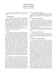
The 18.166 acres of land associated with the HO was given to the University of Hawai‘i in 1961<br />
for scientific purposes, by Executive Order from Hawai‘i’s Governor. The HO is located on the<br />
extinct Kolekole volcanic cinder cone in eastern Maui (Figure 1). The central area of Kolekole<br />
crater is a naturally flattened bowl of ponded ankaramite lava, spatter, and pyroclastic ejecta.<br />
There are believed to be two volcanic vents within the HO site. The primary vent is located<br />
approximately under the new Pan-STARRS facility, located on the southeast quarter of the cone<br />
(Figure 2). The second vent is likely within the wide depression near the western border of the<br />
property.<br />
Figure 1. Haleakala <strong>High</strong> <strong>Altitude</strong> <strong>Observatory</strong> Vicinity Map<br />
1
Haleakal <strong>High</strong> <strong>Altitude</strong> <strong>Observatory</strong> <strong>Stormwater</strong> <strong>Management</strong> <strong>Plan</strong><br />
Ten major structures house the facilities at the HO site (Figure 2). There are also many smaller<br />
support structures such as utility buildings, generators, and cisterns located throughout the site.<br />
The U.S. Air Force (USAF) operates facilities on the northern side of the site, collectively known<br />
as the Maui Space Surveillance Complex. On separately owned land in the western portion of<br />
Kolekole, the Federal Aviation Administration (FAA) and Department of Energy (DOE) maintain<br />
two buildings. The remaining structures within the site are maintained by the IfA.<br />
Figure 2. Haleakala <strong>High</strong> <strong>Altitude</strong> <strong>Observatory</strong> Site Photograph<br />
For the purposes of this <strong>Plan</strong>, we have included the evaluation of stormwater conditions on both<br />
FAA and DOE lands, because stormwater flow paths on Kolekole and natural drainage include<br />
those areas (Figure 3), although UH IfA has no direct responsibility for stormwater management<br />
of those areas.<br />
The isolated location of the facility requires potable water to be trucked in. Non-potable water<br />
collected in cisterns throughout the facility is used for non-drinking purposes, such as flushing<br />
toilets. Wastewater generated at the site is treated using a septic system discharging to a leach<br />
field. A stormwater collection system has been constructed within the HO site. <strong>Stormwater</strong><br />
runoff is collected off impervious surfaces and conveyed to an on-site infiltration basin located<br />
near the western end of the HO property. There are a few locations around the site where<br />
stormwater runoff flows from impervious surfaces associated with HO observatories and<br />
discharges onto the slopes of Haleakal.<br />
2.0 Analysis of Existing <strong>Stormwater</strong> Conditions<br />
<strong>Stormwater</strong> within the HO site is generated from the impervious surfaces associated with the<br />
facility. These surfaces include buildings, roads, and parking areas. The native soils within the<br />
site generally have the capacity to infiltrate all but the most extreme storm events, whereas the<br />
impervious surfaces have no infiltration capacity.<br />
2
Haleakal <strong>High</strong> <strong>Altitude</strong> <strong>Observatory</strong> <strong>Stormwater</strong> <strong>Management</strong> <strong>Plan</strong><br />
The following sections detail the investigation of the hydrologic characteristics of the HO site.<br />
The investigation consisted of identifying runoff flow paths at the facility and assessing<br />
infiltration rates at four locations across the facility. Based on the information determined in the<br />
field, a hydrologic model of the stormwater system was developed and calibrated. The model<br />
allows for the analysis of existing site conditions at the HO as well as the ability to analyze the<br />
impacts to the stormwater system that future expansion at the site may cause.<br />
2.1 <strong>Stormwater</strong> Flow Paths<br />
<strong>Stormwater</strong> generated within the HO site is controlled and conveyed via natural drainage paths<br />
due to site topography, as well as a small collection of stormwater conveyance systems consisting<br />
of concrete channels and culverts. The stormwater collection system was originally designed to<br />
maintain stormwater runoff on paved surfaces and consists of gutters and channels intended to<br />
prevent stormwater from discharging onto native soils adjacent to paved surfaces. Erosion and<br />
lack of maintenance has adversely impacted much of the constructed stormwater system. During<br />
field work for the SWMP, it was noted that concrete channels designed to convey stormwater to<br />
the infiltration basin were blocked with sediment, and fine sediment has accumulated in the<br />
infiltration basin, adversely impacting the infiltration capacity of the native soils.<br />
Ten main stormwater flow paths have been identified at the HO site. Figure 3 illustrates the<br />
existing runoff patterns associated with the facility. A brief description of each flow path is<br />
provided below.<br />
Figure 3. Existing <strong>Stormwater</strong> Drainage Paths at HO<br />
3
Haleakal <strong>High</strong> <strong>Altitude</strong> <strong>Observatory</strong> <strong>Stormwater</strong> <strong>Management</strong> <strong>Plan</strong><br />
Flow Path 1- <strong>Stormwater</strong> runoff from the parking lot associated with the Mees facility leaves the<br />
paved surface and flows down an abandoned road. The runoff then flows across a flat area before<br />
discharging along the southern slopes of the volcanic cone. A concrete channel constructed to<br />
force the runoff to stay on the paved surface and discharge into the infiltration pond failed to<br />
mitigate the issue.<br />
Flow Path 2- Runoff from the upper portion of the site drains onto the road and flows into a<br />
paved gutter. As designed, the runoff was to enter a concrete channel constructed behind the<br />
gathering of buildings and then be conveyed through a culvert into the infiltration basin.<br />
Sediment has completely blocked the concrete channel, which has forced the runoff to flow along<br />
Flow Path 3.<br />
Flow Path 3- Due to the sediment blockage of the original concrete channel, concentrated runoff<br />
flow was redirected along the paved areas associated with the cluster of buildings. An asphalt<br />
berm was constructed to direct the runoff away from the buildings and toward the infiltration<br />
basin. Once the runoff discharges onto the native material, the flow dissipates into multiple<br />
undefined channels leading toward the infiltration basin.<br />
Flow Path 4- <strong>Stormwater</strong> runoff from a small portion of the Air Force complex, along with<br />
runoff from the access road and concrete storage areas, flows along the edge of the road leading<br />
toward the infiltration basin.<br />
Flow Path 5- The native soil in this DOE controlled area appears to have been impacted from<br />
past activities such as parking and storage. Runoff from this area is conveyed to the infiltration<br />
basin through a culvert under the access road.<br />
Flow Path 6- This concrete channel is designed to convey runoff from the road and from the<br />
Faulkes facility. The channel leads to two culverts under the access roads. The lower portion of<br />
the channel is a deposition location for sediment prior to where it enters the first culvert. The<br />
sediment has virtually plugged the channel, forcing runoff to leave the channel and flow toward<br />
the south.<br />
Flow Path 7- The native soil in this portion of the HO and FAA site has been impacted by<br />
construction activities and shows signs of. The compaction of the soil lessens the soil’s<br />
infiltration rate, resulting in runoff that flows toward the south instead of into the infiltration<br />
basin.<br />
Flow Path 8- A portion of the runoff from the FAA facility flows toward the south and<br />
discharges over the slopes of the volcanic cone.<br />
Flow Path 9- Runoff within the concrete channel was designed to flow into the infiltration basin<br />
through a series of two culverts that were placed under access roads. Sediment deposition has<br />
adversely impacted the flow capacity of the two culverts.<br />
Flow Path 10- A large portion of the Air Force facility generates stormwater runoff that flows<br />
into the infiltration basin. The paved surfaces associated with the facility have curbs, which keep<br />
the runoff on paved surfaces until it enters the pipe network that discharges into the infiltration<br />
basin.<br />
4
Haleakal <strong>High</strong> <strong>Altitude</strong> <strong>Observatory</strong> <strong>Stormwater</strong> <strong>Management</strong> <strong>Plan</strong><br />
2.2 Assessment of Infiltration Rates<br />
The majority of the stormwater runoff from the HO, FAA, and DOE sites is conveyed to an<br />
infiltration basin located in the western portion of the site. The infiltration basin appears to be a<br />
natural sink associated with an historic volcanic vent. The rate at which stormwater in the<br />
infiltration basin infiltrates into the underlying soils controls the basin’s ability to store runoff. If<br />
the infiltration rate of the underlying soil is high, stormwater runoff entering the basin infiltrates<br />
as it enters and the basin never ponds or fills. If the underlying soil infiltration rate is low, then<br />
runoff may enter the pond at a rate higher than it can be infiltrated. The excess flow is then<br />
stored in the basin until in can infiltrate. During extended periods of stormwater storage in the<br />
infiltration basin, the underlying soils will become saturated, resulting in lower infiltration rates<br />
and longer draw-down periods for the infiltration basin.<br />
To better understand the infiltration rate of the basin and the surrounding native soils, infiltration<br />
tests were conducted at the HO site. A total of four (4) infiltration tests were conducted within<br />
the HO site on October 11, 2005. Figure 4 shows the locations of the tests throughout the site.<br />
Figure 4. Locations of Infiltration Test at the HO Site<br />
The infiltration tests were conducted using infiltration rings. The two-ring method consists of<br />
driving two open cylinders, one inside the other, into the ground, partially filling the rings with<br />
water and then maintaining the liquid at a constant level. The volume of liquid added to the inner<br />
ring during the test is equal to the volume of water infiltrated into the soil. The volume infiltrated<br />
5
Haleakal <strong>High</strong> <strong>Altitude</strong> <strong>Observatory</strong> <strong>Stormwater</strong> <strong>Management</strong> <strong>Plan</strong><br />
during timed intervals is converted to an incremental infiltration velocity expressed in inches per<br />
hour.<br />
Site 1— Infiltration Basin, fine sediment. Currently, fine sediment transported into the basin<br />
during storm events has been deposited. The fine sediment covers approximately 20% of the<br />
infiltration basin area. Where the sediments are deposited, the infiltration rate of the native soils<br />
has been adversely impacted, causing infiltration into the underlying soil to be limited. The fine<br />
sediments appear to have been deposited into the lower elevation of the pond.<br />
Site 2— Infiltration Basin. The areas of the infiltration basin not impacted by fine sediments are<br />
composed of more native materials. There areas are located along the higher elevations within<br />
the basin.<br />
Site 3— Undisturbed native soil. This test location was chosen to represent the pervious areas<br />
throughout the site. If the resulting infiltration rates are high enough, the undisturbed areas at the<br />
HO can be eliminated from the hydrologic model, as they will not produce runoff.<br />
Site 4— Staging Area. This area, located south of the infiltration basin on FAA property, appears<br />
to be impacted by continued use as a staging area for historic and current construction projects at<br />
the site. Soil in the area has a more compacted look, and it appears that runoff may drain off-site<br />
at the scour hole, which historically caused erosion impacts to the lower access road.<br />
The values shown in Table 1 represent estimated infiltration rates. The site conditions during the<br />
infiltration testing and the duration of the test may result in infiltration rates higher than might be<br />
experienced during a large storm event. The antecedent moisture level in the soils at the start of<br />
the tests was low. During a long storm event, the soil may become saturated, which may reduce<br />
the infiltration capacity of the soil.<br />
Table 1. Estimated Infiltration Rates within the HO Facility<br />
Infiltration Test Location<br />
Site 1 Site 2 Site 3 Site 4<br />
Infiltration Rate,<br />
in/hr<br />
0.25 9.0 >20 3.0<br />
Based on the values shown in Table 1 the infiltration rate for Site 3, the undisturbed native soils,<br />
indicates that most precipitation events at the HO site will be infiltrated directly into undisturbed<br />
soils. Site evidence suggests this to be true. There are little, if any, signs of erosion or surface<br />
drainage in areas not impacted by impervious surfaces at the HO facility. The Site 3 result allows<br />
for not including these areas in the hydrologic model as contributor of stormwater runoff. The<br />
Site 4 infiltration rate is low enough during dry conditions to assume that it produces stormwater<br />
runoff and so the area is included in the hydrologic model.<br />
The infiltration tests conducted within the infiltration basin, sites 1 and 2, indicate that recurring<br />
inundation of the native soils during storm events and deposition of fine sediment may have<br />
impacted the infiltration capacity of the soils.<br />
2.3 Hydrologic Modeling<br />
Development of a hydrologic model for the HO site provides a tool for investigating the<br />
relationship between precipitation and stormwater runoff. Using this modeling tool, estimations<br />
can be made for the peak stormwater runoff flow rate as well as total stormwater runoff flow<br />
6
Haleakal <strong>High</strong> <strong>Altitude</strong> <strong>Observatory</strong> <strong>Stormwater</strong> <strong>Management</strong> <strong>Plan</strong><br />
volumes. The hydrologic modeling was conducted in four phases; model development, model<br />
calibration, hydrologic analysis, and conclusions.<br />
In order to estimate the volume and peak flow rate of stormwater at the HO site, a hydrologic<br />
model of the site was developed. The U.S. Army Corps of Engineers’ Hydrologic Engineering<br />
Center-Hydrologic Modeling System (HEC-HMS) was used to perform the hydrologic analysis<br />
of the HO facility. HEC-HMS is used to simulate event-based or continuous precipitation runoff<br />
processes of a watershed. The model can be used to simulate a range of study areas, from large<br />
natural basins to small urban watersheds.<br />
2.3.1 Model Development<br />
The model uses the watershed characteristics such as basin area, time of concentration,<br />
conveyance system geometry, and land cover to estimate the study area’s reaction to rainfall<br />
events. The HEC-HMS model of the HO site used site records of precipitation and water levels<br />
in the infiltration basin to calibrate the hydrologic model.<br />
Sub-basins. The information gathered during the site investigation for the storm conveyance<br />
system was used to develop the boundaries for the HO sub-basins. The sub-basins are individual<br />
areas that provide direct runoff to the infiltration basin or off site. Generally the sub-basins only<br />
comprise impervious (paved) area. Site conditions show evidence that most of the native lands<br />
do not generate stormwater runoff, so these areas are not included in the model. There are three<br />
exceptions to this: the staging area, the parking area on FAA property, and the area west of the<br />
Air Force access road. All of these areas have been impacted by parking and construction<br />
activities. Figure 5 illustrates the delineations of the individual sub-basin areas included in the<br />
HEC-HMS model. A short description of the individual sub-basins is provided to better<br />
understand the properties of the areas.<br />
Figure 5. Existing conditions HEC-HMS Model Schematic<br />
7
Haleakal <strong>High</strong> <strong>Altitude</strong> <strong>Observatory</strong> <strong>Stormwater</strong> <strong>Management</strong> <strong>Plan</strong><br />
MEES—This refers to the Mees Building and parking lot. The drainage area only includes the<br />
existing paved parking area generates stormwater runoff. Runoff from the roof of the Mees<br />
structure is collected and conveyed to a nearby cistern. Under existing conditions, the runoff<br />
generated from the MEES sub-basin is modeled as leaving the site without flowing to the<br />
infiltration basin. Under future conditions modeling it is assumed the Mees facility drains to the<br />
infiltration basin.<br />
Faulkes—This sub-basin represents the impervious area associated with the Faulkes Telescope<br />
structure. This includes a roof and associated pavement surrounding the building. All runoff is<br />
collected in channels and conveyed to the concrete channel along the access road where it<br />
eventually enters the infiltration basin. A portion of the access road also is included in this<br />
drainage area.<br />
Air Force—The Air Force sub-basin reflects the portion of the Air Force facilities that drain to<br />
the infiltration basin. The sub-basin includes the roofs and paved parking area in the site. The<br />
final delineation was determined using site maps and site inspections that detailed the stormwater<br />
system and grading of the area.<br />
Gamma 1—The Gamma Ray building complex drains to two locations. The Gamma 1 drainage<br />
area includes a large portion of the access road from the Mees Building to the Gamma Ray area.<br />
An asphalt berm has been constructed that forces runoff to discharge onto native material near the<br />
southern edge of the area and flow through random channel into the infiltration basin.<br />
Gamma 2—This sub-basin represents the northern portion of the Gamma Ray facility. Runoff<br />
from this area discharges onto native material in multiple areas where it eventually flows to the<br />
infiltration basin.<br />
FAA1—The southern portion of the FAA site drains toward the culvert inlet at the upstream side<br />
of the access road the FAA facility. Runoff is combined with runoff from the Faulkes facility and<br />
conveyed into the infiltration basin.<br />
FAA2—The northern portion of the FAA facility drains to short the open concrete channel near<br />
the paved parking area. The flow is combined with all the runoff entering the upstream culvert<br />
and then conveyed into the infiltration basin.<br />
Staging Area—The pervious area south of the access road has been impacted by numerous<br />
activities. The native soils have been compacted by using the area for construction storage and<br />
driving vehicle across it. The topography of the site as well as localized erosion patterns suggest<br />
this area does not currently drain to the infiltration basin but instead discharges to the south on to<br />
the slopes of the Kolekole cinder cone. Under future conditions the hydrologic model includes<br />
the staging area as contributing runoff to the infiltration basin.<br />
Overlook—The Overlook area is location to the west of the access road to the Air Force site.<br />
This area too has been impacted by storage and/or vehicle traffic. The sub-basin drains to a<br />
culvert under the access road and discharges into the infiltration basin. The Overlook sub-basin<br />
also includes a small portion of paved area associated with the Department of Energy facility.<br />
Misc Imperv—There are multiple impervious areas at the HO site that drain directly into the<br />
infiltration. These include the access road to the Air Force site and the concrete pad adjacent to<br />
the infiltration area. These areas were all combined into one sub-basin since the hydrologic<br />
characteristics of the sites are similar.<br />
8
Haleakal <strong>High</strong> <strong>Altitude</strong> <strong>Observatory</strong> <strong>Stormwater</strong> <strong>Management</strong> <strong>Plan</strong><br />
Future Mirror Coating Facility—Expansion plans associated with the existing Air Force facility<br />
include a new structure and parking locations. Based on the proposed locations of the expansion<br />
facilities, they will all drain into the infiltration basin.<br />
Time of Concentration (Tc). Tc is the duration of time for runoff to travel from the<br />
hydraulically most distant point of the sub-basin to a point of interest within the sub-basin. Due<br />
to the small sub-basin area and paved nature of the site, Tc was set at 5 minutes for each subbasin.<br />
Five minutes is generally considered the minimum Tc for hydrologic modeling. Using a<br />
shorter Tc will provide for higher peak flows, resulting in conservative (higher) peak flow<br />
estimations.<br />
Curve Number (CN). CN is a numeric representation of the hydrologic characteristic of the<br />
surface within an area. The major factors impacting the determination of a CN are hydrologic<br />
soil group (HSG), cover type, and land use. The HSG is based on the infiltration rate of a soil.<br />
The HSG system uses A, B, C, or D to indicate the soil infiltration capacity, ranging from high<br />
(HSG=A) to low (HSG=D). The infiltration rate of the soil impacts what portion of the<br />
precipitation enters the soil and what portion becomes runoff. Cover type is used to indicate the<br />
impacts of vegetation and interception. If an area is heavily vegetated, the vegetation will<br />
intercept precipitation before it can be either infiltrated or become runoff. Land use is considered<br />
to show the impact of whether an area is lawn, field, pasture, cropland, etc. Based on the<br />
combination of the three parameters, a CN is assigned to the area. CN values can range from 30<br />
(low runoff potential) to 100 (all rainfall is turned into runoff).<br />
For the HO, the only areas modeled are impervious areas except for the three exceptions of<br />
impacted soil area described above. The CN value for impervious surfaces such as street/road is<br />
98. For the impacted pervious sites, a CN of 87 was assigned. Table 2 shows the parameter<br />
values used in the HO HEC-HMS model.<br />
Table 2. HEC-HMS Parameters for the HO Facility<br />
Basin Area<br />
Time of<br />
Drainage Basin<br />
(ft 2 SCS Curve<br />
)<br />
Concentration,<br />
Name<br />
Number<br />
Impervious Pervious Tc, min<br />
Mees Bldg 4,855 5 98<br />
Faulkes 5,812 5 98<br />
Air Force 65,025 5 98<br />
Gamma 1 13,573 5 98<br />
Gamma 2 8,396 5 98<br />
FAA 1 3,574 5 98<br />
FAA 2 11191 5267 5 98 and 87<br />
Staging Area 0 26,070 5 98 and 87<br />
Overlook 1005 9049 5 98 and 87<br />
Misc Imperv 18,105 5 98<br />
Future Mirror<br />
Coating Facility<br />
12642 5 98<br />
Both UH and the Air Force plan to expand their facilities at the HO site in the future. The Air<br />
Force plans to construct a Mirror Coating Facility and associated parking. The Air Force<br />
expansions will discharge to the infiltration basin. The UH is planning to construct the proposed<br />
Advanced Technology Solar Telescope (ATST) facility near the Mees building. This facility will<br />
include a structure and replacement of current paved parking. The stormwater runoff from the<br />
9
Haleakal <strong>High</strong> <strong>Altitude</strong> <strong>Observatory</strong> <strong>Stormwater</strong> <strong>Management</strong> <strong>Plan</strong><br />
ATST structure will be collected and transferred to an existing cistern. Improvements to the<br />
existing Mees building parking will redirect runoff from flowing offsite to draining to the<br />
infiltration basin. These two site changes are reflected in HEC-HMS model representing future<br />
expansion at the HO site. The future model is intended to demonstrate impacts to the stormwater<br />
system due to the increase in impervious area at the HO site.<br />
Infiltration Basin. The existing infiltration basin has been included in the HEC-HMS model of<br />
the HO site. The infiltration basin is modeled as a reservoir, with the infiltration rate being<br />
modeled as the outflow from the basin. To effectively model the basin, HEC-HMS considers the<br />
surface area of the stored water in the basin associated with varying depths, along with the<br />
outflow from the basin associated with water level. As the water level in the basin increases, the<br />
surface area associated with the water surface also increases. As the surface area of the water<br />
increases, the rate of infiltration also increases because water covers more land.<br />
Using the available topography of the infiltration basin (Figure 6) along with the recorded<br />
infiltration rates within the basin, the relationship between basin depth and surface area was<br />
developed, as was the relationship between surface area and the infiltration rate (outflow) of the<br />
basin.<br />
The total storage volume of the infiltration basin is estimated to be 1.5 ac-ft. The estimation<br />
assumes the maximum storage occurs at elevation 9922 ft. The topography survey reveals that a<br />
water level higher than 9920 feet within the infiltration basin will cause runoff to back up through<br />
the culvert at the south end of the basin. As the water level increases above the elevation of 9920<br />
ft, runoff will start to be stored in the staging area along the south of the site. Based on the site<br />
topography, any water surface elevation above 9922 feet will likely discharge uncontrolled<br />
toward the south, onto the volcanic cone.<br />
Figure 6. Topographic Map of the Infiltration Basin at the HO Site<br />
10
Haleakal <strong>High</strong> <strong>Altitude</strong> <strong>Observatory</strong> <strong>Stormwater</strong> <strong>Management</strong> <strong>Plan</strong><br />
2.3.2 Hydrologic Model Calibration<br />
Model calibration is conducted in an attempt to verify that the parameters used in the modeling<br />
effort reproduce recorded events at the site. In order to calibrate the HO model, one or more<br />
storm events must result in recorded rainfall amounts along with coinciding water level<br />
measurements in the infiltration basin. There are multiple weather stations in place around the<br />
HO facility recording precipitation. A water level gage was installed in the infiltration basin at<br />
the onset of the SWMP project. Both sets of recorded data were used during the calibration<br />
efforts of the HEC-HMS model.<br />
Rainfall Gage<br />
The rain gage instrument is mounted on a 10-meter tower, 30<br />
meters east of the Mees building. The rain gage is a<br />
Climatronics 100508 6-inch tipping bucket (.01-inch resolution).<br />
Precipitation is recorded every 10 minutes. This project required<br />
the precipitation record for the same time period as the water<br />
level recording in the infiltration basin.<br />
Infiltration Basin Water Level Gage<br />
As part of this SWMP, a water level gage was installed at the<br />
infiltration basin. The gage recorded the depth of water in the<br />
basin at 15-minute intervals from October 11, 2005, to February<br />
3, 2006. The infiltration basin is dry the majority of the time,<br />
with inflows into the basin’s intermittent ponds only occurring<br />
after rainfall events at the summit of Haleakala.<br />
Calibration Results<br />
Using the recorded precipitation record along with the water levels recorded in the infiltration<br />
basin, the hydrologic model of the HO was calibrated to reproduce the recorded rainfall events’<br />
impacts on the infiltration basin at the HO site. Figure 7 shows the recorded infiltration basin<br />
water surface elevations compared to the HEC-HMS model results for the same rainfall event.<br />
Figure 7. Comparison of Recorded and Modeled Water Surface Elevations<br />
Water Surface Elevation, feet<br />
9920.5<br />
9920<br />
9919.5<br />
Recorded Basin WSE<br />
HMS_Results<br />
9919<br />
9918.5<br />
9918<br />
18-Jan-06<br />
20-Jan-06<br />
22-Jan-06<br />
24-Jan-06<br />
26-Jan-06<br />
28-Jan-06<br />
30-Jan-06<br />
1-Feb-06<br />
3-Feb-06<br />
5-Feb-06<br />
7-Feb-06<br />
Date<br />
11
Haleakal <strong>High</strong> <strong>Altitude</strong> <strong>Observatory</strong> <strong>Stormwater</strong> <strong>Management</strong> <strong>Plan</strong><br />
Based on the water surface elevation (WSE) recorded in the infiltration basin, there was a storm<br />
event at the HO site near January 24, 2006. Review of the precipitation recorded noted missing<br />
recorded data for the entire day of January 24, 2006. In the calibration modeling effort, the<br />
missing rainfall data was replaced with 0.00 readings to provide continuity to the HEC-HMS<br />
model.<br />
Based on the modeling results shown on Figure 7, the HEC-HMS hydrologic model output<br />
provides a reasonable simulation of the water surface elevations in the infiltration basin at the HO<br />
site. The model reacts well to the water levels rising and peaking, but the model results in faster<br />
initial drainage of the pond and then a much longer final drying out of the basin. The changing<br />
dynamics of the site’s soil infiltration rates cannot be adequately replicated with the HEC-HMS<br />
model. However, the HEC-HMS model does adequately replicate the peaks, and this is the more<br />
significant output of the model because it reflects whether the basin provides the required storage<br />
volume to mitigate the impervious surfaces associated with the HO facility.<br />
2.3.3 Hydrologic Analysis<br />
The calibrated HEC-HMS model was used to simulate the infiltration basin’s response to rainfall<br />
events for various return frequencies. A Type I SCS, 24-hour unit hydrograph was used to model<br />
the impacts of the 1-year through 100-year storm events on the infiltration basin. Table 3<br />
contains the total precipitation for the various 24-hour storm events. The storm precipitation<br />
totals were estimated using the isopluvial maps presented in Technical Paper No. 43, Rainfall-<br />
Frequency Atlas of the Hawaiian Islands (U.S. Department of Commerce, 1962).<br />
Table 3. 24-Hour Rainfall Totals Associated with HO<br />
24 Hour Storm Event Precipitation Total (inches)<br />
1-Year 2-Year 5-Year 10-Year 25-Year 50-Year 100-Year<br />
4.0 5.0 8.0 9.0 10.0 13.0 15.0<br />
Technical Paper No. 43 provides total rainfall totals associated with multiple storm durations<br />
including, 30-minute, 1-hour, 2-hour, 6-hour, and 12-hour storms. The 24-hour storm event was<br />
selected for modeling purposes because this duration of storm will provide the largest volume of<br />
rainfall, resulting in the largest volume of stormwater runoff.<br />
Using the calibrated HEC-HMS model, the multiple 24-hour storm events were modeled to<br />
estimate the peak runoff flow rate and the peak WSE in the infiltration basin. Table 4 contains<br />
the results for the existing conditions model. The peak WSE shown in the table assumes that<br />
when the WSE in the infiltration basin exceeds 9922.0 feet, the basin will overtop, and runoff will<br />
discharge off site toward the south. Because the runoff can flow unrestricted out of the basin at<br />
elevations above 9922.0 feet, flow out of the basin would equal flow into the basin. The result<br />
would be that the basin WSE would not increase much above the 9922.0 feet elevation.<br />
Table 4. Existing Conditions HEC-HMS Modeling Results for the Infiltration Basin<br />
Drainage<br />
Peak <strong>Stormwater</strong> Runoff Rates, cfs<br />
Basin 1-Year 2-Year 5-Year 10-Year 25-Year 50-Year 100-Year<br />
Peak<br />
Inflow, cfs<br />
8.7 11.0 17.7 19.9 22.2 28.9 33.4<br />
Maximum<br />
WSE<br />
9920.3 9920.6 9921.5 9921.8 9922.0 9922 (+) 9922 (+)<br />
12
Haleakal <strong>High</strong> <strong>Altitude</strong> <strong>Observatory</strong> <strong>Stormwater</strong> <strong>Management</strong> <strong>Plan</strong><br />
The future conditions scenario model was then used to estimate the peak runoff rates and WSE in<br />
the infiltration basin. The future conditions model assumes the Mees parking lot, and future Air<br />
Force expansion will all be conveyed into the infiltration basin. From the current architectural<br />
plans for ATST, It is assumed that the entire runoff volume from the proposed ATST facility will<br />
be captured for use and not play a role in this scenario. The results are shown in Table 5.<br />
Table 5. Site Expansion Conditions HEC-HMS Modeling Results for the Infiltration Basin<br />
Drainage<br />
<strong>Stormwater</strong> Runoff Volumes, cubic feet<br />
Basin 1-Year 2-Year 5-Year 10-Year 25-Year 50-Year 100-Year<br />
Peak<br />
Inflow, cfs<br />
11.1 14.1 22.9 25.9 28.8 37.6 43.5<br />
Maximum<br />
WSE<br />
9920.6 9921.0 9922 (+) 9922 (+) 9922 (+) 9922 (+) 9922 (+)<br />
As described earlier, the peak WSEs shown in the Table 5 assumes the uncontrolled outflow from<br />
the basin with WSE elevation above 9922.0 feet. A more detailed topographic survey of the open<br />
area south of the infiltration basin would determine the elevation at which the pond would start to<br />
overtop.<br />
2.3.4 Conclusions<br />
Based on the results of the hydrologic modeling efforts, under existing drainage conditions the<br />
infiltration basin appears to adequately contain the stormwater runoff for all but the most extreme<br />
storm events (50-year and above). Under proposed conditions, including facility expansion and<br />
containment of currently flowing off-site runoff, the infiltration basin is estimated to overtop at<br />
storm events larger than the 5-year recurrence interval. Generally, containment of larger storm<br />
events is considered to be for flood control only. When water quality is the concern of the site,<br />
then controlling the smaller, more commonly occurring events is important. Since neither of these<br />
concerns applies to HO, we consider the containment for stormwater runoff to be adequate.<br />
Additional stormwater best management practices are desired at the HO site to contain all<br />
stormwater runoff generated within the HO facility. The remaining sections of this SWMP<br />
contain best management practices (BMP) to be considered during design and construction of the<br />
future HO site expansion. Also included are maintenance practices that are intended to improve<br />
the effectiveness of the existing and future stormwater management systems.<br />
3.0 Construction Best <strong>Management</strong> Practices<br />
The County of Maui has developed BMPs required during construction for the control of erosion<br />
from stormwater. The following text is taken verbatim from the county code and edited to<br />
contain only sections applicable to the HO site.<br />
3.1 County of Maui Code, Section 20.08.035, Minimum BMPs<br />
Regardless of whether a permit is required pursuant to this chapter, all grading, grubbing and<br />
stockpiling activities shall provide bmps to the maximum extent practicable to prevent damage by<br />
sedimentation to streams, watercourses, natural areas and the property of others. It shall be the<br />
13
Haleakal <strong>High</strong> <strong>Altitude</strong> <strong>Observatory</strong> <strong>Stormwater</strong> <strong>Management</strong> <strong>Plan</strong><br />
permittee's and the property owner's responsibility to ensure that the bmps are satisfactorily<br />
implemented.<br />
Drainage. On-site drainage shall be handled in such a way to as to control erosion,<br />
prevent damage to downstream properties and to return waters to the natural drainage<br />
course in a manner, which minimizes sedimentation or other pollution to the maximum<br />
extent practicable.<br />
Dust Control. All areas disturbed by construction activities shall control dust emissions to<br />
the maximum extent practicable through the application of bmps that may include<br />
watering with trucks or sprinklers, erection of dust fences, and limiting the area of<br />
disturbance.<br />
Vegetation. Whenever feasible, natural vegetation, especially grasses, should be retained.<br />
If it is necessary to be removed, trees, timber, plants, shrubbery and other woody<br />
vegetation, after being uprooted, displaced or dislodged from the ground by excavation,<br />
clearing or grubbing, shall not be stored in or deposited along the banks of any stream,<br />
river or natural watercourse. The director may require the removal and disposal of such<br />
vegetation from the site within a reasonable time but not to exceed three months.<br />
Erosion Controls. All disturbed areas shall be stabilized with erosion control measures<br />
that may include: staging construction: clearing only areas essential for construction;<br />
locating potential nonpoint pollutant sources away from steep slopes, water bodies, and<br />
critical areas; routing construction traffic to avoid existing or newly planted vegetation;<br />
protecting natural vegetation with fencing, tree armoring, and retaining walls or tree<br />
wells; stockpiling topsoil, covering the stockpile to prevent dust, and reapplying the<br />
topsoil; covering or stabilizing all soil stockpiles; using wind erosion control; intercepting<br />
runoff above disturbed slopes and conveying it to a permanent channel or storm drain;<br />
constructing benches, terraces, or ditches at regular intervals to intercept runoff on long<br />
or steep disturbed or man-made slopes; providing linings or other method to prevent<br />
erosion of storm water conveyance channels; using check dams where needed to slow flow<br />
velocities; using seeding and fertilizing, mulching, sodding, matting, blankets, bonded<br />
fiber matrices, or other effective soil erosion control technique; and providing vehicle<br />
wheel wash facilities for vehicles before they leave the site.<br />
Sediment Control. In addition to the erosion control measures of this section, providing<br />
practices to capture sediment that is transported in runoff to minimize the sediment from<br />
leaving the site. Filtration and detention (gravitational settling) are the main processes<br />
used to remove sediment from construction site runoff. Sediment control measures include<br />
sediment basins; sediment traps; filter fabric silt fences; straw bale, sand bag, or gravel<br />
bag barriers; inlet protection; stabilized construction entrances, and other measures to<br />
minimize off site tracking of sediment by construction vehicles; and vegetated filter strips.<br />
Material and Waste <strong>Management</strong>. Measures to insure the proper storage of toxic<br />
material and prevent the discharge of pollutants associated with construction materials<br />
and wastes shall be implemented.<br />
Erosion Control <strong>Plan</strong>.<br />
The erosion control plan shall employ best management practices to the maximum extent<br />
practicable to prevent or reduce pollutants from water bodies, including sediment and other<br />
contaminants, in discharges from a construction site. The erosion control plan shall include<br />
14
Haleakal <strong>High</strong> <strong>Altitude</strong> <strong>Observatory</strong> <strong>Stormwater</strong> <strong>Management</strong> <strong>Plan</strong><br />
drawings with notes and details on the bmps to be implemented for the project, pursuant to<br />
section 20.08.035, Minimum bmps. The erosion control plan shall address the following to the<br />
extent applicable:<br />
a. Stabilization of denuded areas,<br />
b. Protection/stabilization of soil stockpiles,<br />
c. Permanent soil stabilization,<br />
d. Establishment and maintenance of permanent vegetation,<br />
e. Protection of adjacent properties and water bodies,<br />
f. Sediment trapping measures,<br />
g. Sediment basins,<br />
h. Cut and fill slopes (terracing),<br />
i. <strong>Stormwater</strong> management,<br />
j. Sequence of construction operations, including phased and successive development projects,<br />
k. Stabilization of waterways and outlets,<br />
l. Storm sewer inlet protection,<br />
m. Control of access and vehicular movement,<br />
n. Vehicular control on residential lots during construction,<br />
o. Working in or crossing watercourses,<br />
p. Underground utility construction,<br />
q. Timely installation of permanent erosion and sediment control,<br />
r. Maintenance of erosion control facilities,<br />
s. Protection of existing vegetation, and<br />
t. Dust control.<br />
Drainage <strong>Plan</strong> and Report.<br />
The drainage plan and report shall provide hydrologic and hydraulic calculations and<br />
information in accordance with title 15, "rules for the design of storm drainage facilities in the<br />
County of Maui," and revisions thereof, and other standards approved by the department of<br />
public works and waste management. The potential effects of the water runoff from the entire<br />
area covered by the permit on lower lying housing, business and other developments and on<br />
water bodies shall be included in the drainage plan and report.<br />
Engineer's Soils Report.<br />
In the event a proposed cut or fill is greater than fifteen feet in height, or in the event any fill is in<br />
the water, including wetlands and streams or in the event the fill material will be a highly plastic<br />
clay, submit an engineer's soils report, to include data regarding the nature, distribution and<br />
engineering characteristics of existing soils, the subsurface conditions at the site or the presence<br />
of ground water when detected, and recommending the limits for the proposed grading, the fill<br />
material to be used and the manner of placing it, including the height and slopes of cut and fill<br />
sections. Terminology for describing soils in the engineer's soils report, insofar as practical, shall<br />
be based on the soil survey of islands of Kaui, Oahu, Maui, Molokai and Lanai, State of Hawaii,<br />
or its revisions, issued by the soil conservation service in connection with the university of<br />
Hawaii agriculture experiment station.<br />
Responsibility.<br />
The permittee and the property owner shall be responsible for construction, installation, and<br />
maintenance of structural and nonstructural bmps at construction sites in accordance with the<br />
approved erosion control and drainage plans. The adequacy of bmps employed, the<br />
implementation of correction action if needed and the cost thereof shall be the responsibility of<br />
the permittee and the property owner. (Ord. 2684 § 8, 1998: Ord. 816 § 1 (part), 1975: prior<br />
code § 24-2.2(b))<br />
15
Haleakal <strong>High</strong> <strong>Altitude</strong> <strong>Observatory</strong> <strong>Stormwater</strong> <strong>Management</strong> <strong>Plan</strong><br />
3.2 <strong>Stormwater</strong> Best <strong>Management</strong> Practices<br />
Four BMPs are recommended to address existing and potential future stormwater management<br />
issues at the HO facility.<br />
Rainwater Harvesting/Cisterns<br />
Cisterns are currently being used at the Mees <strong>Observatory</strong> to store roof runoff for reuse as nonpotable<br />
water associated with flushing the toilets at the facility. This practice should be used<br />
where appropriate throughout the facility. In addition, new technologies can be used to store and<br />
treat the collected runoff from rooftops for potable water reuse.<br />
Infiltration Trenches/Dry Wells<br />
Infiltration-related stormwater BMPs are designed to remove stormwater runoff from the<br />
collection system. The runoff is contained on site and infiltrated into the existing soils. For the<br />
HO site, the existing soil conditions are ideal for this type of stormwater runoff control. The high<br />
infiltration rates associated with the undeveloped, porous soils allows for quick removal of<br />
stormwater from the collection system. The use of onsite infiltration practices also limits the<br />
need for the construction of a conveyance system, such as channels or pipes. The infiltrationbased<br />
BMPs can be used to manage runoff from any impervious surface such as rooftops or<br />
paved parking areas.<br />
Covered Collection Systems<br />
An existing stormwater conveyance issue at the HO is the amount of sediment accumulating in<br />
the open channels used to transport runoff into the infiltration basin. Many of the channels are<br />
constructed across the slope, which allows sediment from the upslope of the channel to be<br />
transported by gravity into the channel. In locations where the gradient of the channel is low, the<br />
stormwater runoff does not provide enough energy to transport the sediment; instead, the<br />
sediment is deposited and it just accumulates. Eventually the sediment blocks the channel, and<br />
stormwater is forced out of the channel and onto unprotected native material where erosion can<br />
occur. Future stormwater channels should be constructed as enclosed systems, either pipes or<br />
covered channels, to prevent sediment accumulation in the future.<br />
Roadside Berms and Curbs<br />
Asphalt curbs and/or berms should be constructed to keep stormwater runoff on paved surfaces.<br />
Currently, stormwater runoff generated on much of the existing road surfaces at the HO site is<br />
allowed to flow onto unpaved areas. At the access road below the Faulkes facility, the runoff<br />
leaves the road surface, flows across unpaved areas, and then enters into a concrete channel<br />
where it is conveyed to the infiltration basin. The concern is that when the runoff flows across<br />
the unpaved areas, it starts to erode the supporting edge of the road, which undermines the paved<br />
section and causes cracks to appear. The runoff also transports sediment from the unpaved areas<br />
into the concrete channel, where the sediment is either transported into the infiltration basin or<br />
deposited in the concrete channel, adversely impacting the conveyance capacity of the channel.<br />
This also occurs along the access road to the Air Force facility.<br />
3.3 Operation and Maintenance <strong>Plan</strong><br />
The existing stormwater conveyance system within the HO facility was designed to convey<br />
runoff generated from rainfall events. The system limits the erosion capability of runoff by<br />
keeping the flow on hardened surfaces or within channels. When the runoff has the opportunity<br />
to flow over native, unprotected soil, the stormwater runoff causes adverse erosion impacts. This<br />
16
Haleakal <strong>High</strong> <strong>Altitude</strong> <strong>Observatory</strong> <strong>Stormwater</strong> <strong>Management</strong> <strong>Plan</strong><br />
Operation and Maintenance <strong>Plan</strong> section of the SWMP provides techniques required to maintain<br />
the existing and future collection system associated with the HO facility.<br />
Sediment Control<br />
In accordance with the IfA Long Range Development <strong>Plan</strong>, all sediment or rock displaced during<br />
maintenance or construction must remain on site, in observance of cultural protocols. The<br />
material removed from ditches can be spread around the site or used to repair berms, potholes,<br />
etc.<br />
Infiltration Basin<br />
The infiltration basin is a key element for the control of stormwater at the HO facility.<br />
Maintaining the basin will ensure the HO site can continue to effectively control stormwater<br />
runoff while not adversely impacting the natural conditions of the HO site and adjacent area.<br />
Sediment that has been deposited into the basin should be removed to another location on site.<br />
The deposition of sediment in the basin adversely impacts the facility in two ways: (1) The<br />
sediment deposited in the basin diminishes the storage capacity for stormwater runoff, (2) fine<br />
material clogs the open areas I the soil reducing the soil’s ability to infiltrate stormwater. As<br />
impervious surfaces increase at the HO facility due to expansion at the site, the volume of the<br />
stormwater generated and conveyed into the infiltration basin will increase, so maintaining the<br />
basin’s storage and infiltration capacity is very important.<br />
The removal and placement of sediment from the infiltration basin must comply with the criteria<br />
set forth in the LRDP for the site. All sediment removed from the basin must remain on<br />
Haleakala. The sediment can be spread out over the HO site or it can be transported from the HO<br />
site to other locations on the mountain. If the removed sediment remains at the HO site, the<br />
control of dust during the removal and placement phases is very important.<br />
Channels<br />
The concrete channels should be inspected routinely after every wet season. During the<br />
inspection, all accumulated sediment should be removed from the channel and distributed within<br />
the site. If the channel is constructed across a slope, the removed sediment should be placed in a<br />
location on the down gradient side of the channel. Placing the removed sediment below the<br />
channel will ensure the material is not re-transported back into the channel.<br />
Not only should material within the channel be removed, but if accumulated sediment is noticed<br />
near the channel, it too should be moved or redistributed to eliminate the chance of the material<br />
being transported into the channel.<br />
Mees Facility<br />
The un-maintained concrete channel designed to convey runoff from the parking area to the road<br />
needs to be redesigned and reconstructed. The current channel was poorly formed and did not<br />
have adequately stable base material. As a result, the channel cracked and runoff was allowed to<br />
flow under the channel, causing additional erosion. The proposed design should take into account<br />
the causes of the current channel failures and also provide protection from vehicular damage due<br />
to its proximity to the existing Mees building parking lot.<br />
17