op5 ADAM Manual
op5 ADAM Manual
op5 ADAM Manual

Create successful ePaper yourself
Turn your PDF publications into a flip-book with our unique Google optimized e-Paper software.
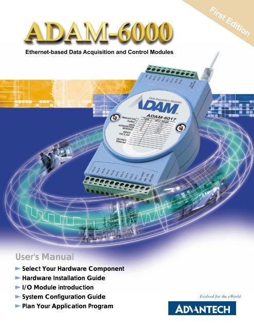
First Edition<br />
Ethernet-based Data Acquisition and Control Modules<br />
User's <strong>Manual</strong><br />
Select Your Hardware Component<br />
Hardware Installation Guide<br />
I/O Module introduction<br />
System Configuration Guide<br />
Plan Your Application Program<br />
Evolved for the eWorld
Copyright Notice<br />
This document is copyrighted, 2002, by Advantech Co., Ltd. All rights are<br />
reserved. Advantech Co., Ltd., reserves the right to make improvements to the<br />
products described in this manual at any time without notice.<br />
No part of this manual may be reproduced, copied, translated or transmitted in any<br />
form or by any means without the prior written permission of Advantech Co., Ltd.<br />
Information provided in this manual is intended to be accurate and reliable.<br />
However, Advantech Co., Ltd. assumes no responsibility for its use, nor for any<br />
infringements upon the rights of third parties which may result from its use.<br />
Acknowledgments<br />
IBM and PC are trademarks of International Business Machines Corporation.<br />
Part No. 2001600000 First Edition<br />
Printed in Taiwan Mar. 2002
Product Warranty<br />
Advantech warrants to you, the original purchaser, that each of its products will be<br />
free from defects in materials and workmanship for two year from the date of<br />
purchase.<br />
This warranty does not apply to any product which have been repaired or altered by<br />
other than repair personnel authorized by Advantech, or which have been subject to<br />
misuse, abuse, accident or improper installation. Advantech assumes no liability as a<br />
consequence of such events under the terms of this Warranty.<br />
Because of Advantech’s high quality-control standards and rigorous testing, most of<br />
our customers never need to use our repair service. If an Advantech product ever does<br />
prove defective, it will be repaired or replaced at no charge during the warranty period.<br />
For out-of-warranty repairs, you will be billed according to the cost of replacement<br />
materials, service time and freight. Please consult your dealer for more details.<br />
If you think you have a defective product, follow these steps:<br />
1. Collect all the information about the problem encountered (e.g. type of PC, CPU<br />
speed, Advantech products used, other hardware and software used etc.). Note<br />
anything abnormal and list any on-screen messages you get when the problem<br />
occurs.<br />
2. Call your dealer and describe the problem. Please have your manual, product, and<br />
any helpful information readily available.<br />
3. If your product is diagnosed as defective, you have to request an RAM number.<br />
When requesting an RMA (Return Material Authorization) number, please access<br />
ADVANTECH's RMA web site: http://www.advantech.com.tw/rma. If the web<br />
sever is shut down, please contact our office directly. You should fill in the<br />
"Problem Repair Form", describing in detail the application environment,<br />
configuration, and problems encountered. Note that error descriptions such as<br />
"does not work" and "failure" are so general that we are then required to apply our<br />
internal standard repair process.<br />
4. Carefully pack the defective product, a completely filled-out Repair and<br />
Replacement Order Card and a photocopy of dated proof of purchase (such as your<br />
sales receipt) in a shippable container. A product returned without dated proof of<br />
purchase is not eligible for warranty service.<br />
5. Write the RMA number visibly on the outside of the package and ship it prepaid to<br />
your dealer.
Technical Support<br />
We want you to get the maximum performance from your products. So if you run into<br />
technical difficulties, we are here to help. For most frequently asked questions you<br />
can easily find answers in your product documentation. Moreover, there are a huge<br />
database about trouble-shooting and knowledge Base as technical reference on our<br />
website. These answers are normally a lot more detailed than the ones we can give<br />
over the phone.<br />
So please consult this manual or the web site first. If you still cannot find the answer,<br />
gather all the information or questions that apply to your problem and, with the<br />
product close at hand, call your dealer. Our dealers are well trained and ready to give<br />
you the support you need to get the most from your Advantech products. In fact, most<br />
problems reported are minor and are able to be easily solved over the phone.<br />
In addition, free technical support is available from Advantech engineers every<br />
business day. We are always ready to give advice on application requirements or<br />
specific information on the installation and operation of any of our products.<br />
Website information:<br />
You can access the most current support on our website:<br />
http://www.advantech.com<br />
Then click the title of “Service & Support” for further product information.
<strong>Manual</strong> Organization<br />
This <strong>Manual</strong> has six chapters, three appendices.<br />
The following table lists each chapter or appendices with its corresponding title and a brief overview of the topics covered in it.<br />
Chapter /<br />
Appendix<br />
Title<br />
Topics Covered<br />
1 Understanding Your System<br />
2 Selecting Your Hardware<br />
3 Hardware Installation Guide<br />
4 I/O Module Introduction<br />
5 System Configuration Guide<br />
6 Planning Your Application Program<br />
A<br />
Design Worksheets<br />
Introduces the suitable applying industries and the position<br />
in an Ethernet remote system. Summarize the features and<br />
the common specification of <strong>ADAM</strong>-6000. Explains the<br />
functions of the LED indicators.<br />
Provides a briefly selection chart and specification table of<br />
<strong>ADAM</strong>-6000 I/O modules for users to organize their<br />
system easily. Give a direction to calculate system capacity<br />
and select a certain power supply. Recommend a standard<br />
for communication cable and connector.<br />
Lists the necessary components and proper environment in<br />
installing process. Describes the Hardware dimension and<br />
the way to place or mount it. Explains the rule of mapping<br />
I/O address. Describes the wiring and connecting detail for<br />
<strong>ADAM</strong>-6000.<br />
Introduces the detail specifications, functions and<br />
application wiring of each <strong>ADAM</strong>-6000 I/O modules.<br />
Guides users to use Windows Utility for network &<br />
security setting, I/O range configuration, accuracy<br />
calibration, command setting, and so on.<br />
Demonstrate the standard web page operation and the<br />
customization web page development. Introduces the<br />
functions and structure of DLL drivers and command sets.<br />
Explain how to integrate these programming tools to plan<br />
your application program.<br />
Provides organized worksheets for users to establish<br />
system configuration document in order.<br />
B<br />
Data Formats and I/O Range<br />
Provides detail information about Data formats and I/O<br />
Range of Analog Module.<br />
C Grounding Reference Explains the concepts about field grounding and shielding.
How to use this manual<br />
The following flow chart demonstrates a thought process that you can use when you<br />
plan your <strong>ADAM</strong>-6000 Ethernet Data Acquisition and Control System.
Chapter 1<br />
Understanding Your System<br />
Using this Chapter<br />
If you want to read about<br />
Go to page<br />
Introduction 1-2<br />
Major Feature 1-3<br />
Technical Specification 1-5<br />
LED Status of <strong>ADAM</strong>-6000 I/O Modules 1-7
1-1 Introduction<br />
<strong>ADAM</strong>-6000, Ethernet-based data acquisition and control module, provides I/O, data<br />
acquisition and networking in one module to build a cost-effective, distributed<br />
monitoring, and control solutions for a wide variety of industries and applications.<br />
Through de-factor standard Ethernet networking, <strong>ADAM</strong>-6000 retrieves I/O values<br />
from sensors and publishes these real-time I/O value to networking nodes at local area<br />
network or Intranet, Internet. With Ethernet-enabled technology, <strong>ADAM</strong>-6000 series<br />
modules build up a cost-effective DA&C system for Building Automation,<br />
environmental monitoring, facility management and eManufacturing applications.<br />
Please refer to Figure 1-1 to have a brief view of <strong>ADAM</strong>-6000 system architecture.<br />
Figure 1-1 <strong>ADAM</strong>-6000 System Architecture
1-2 Major Features<br />
1-2-1 Ethernet-enabled DA&C I/O Modules<br />
<strong>ADAM</strong>-6000 is based on the popular Ethernet networking standards used today in most business<br />
environments. Users can easily add <strong>ADAM</strong>-6000 I/O modules to existing Ethernet networks or use<br />
<strong>ADAM</strong>-6000 modules in new Ethernet-enabled eManufacturing networks. <strong>ADAM</strong>-6000 module features<br />
a 10/100 Mbps Ethernet chip and supports industrial popular Modus/TCP protocol over TCP/IP for data<br />
connection. <strong>ADAM</strong>-6000 also supports UDP protocol over Ethernet networking. With UDP/IP,<br />
<strong>ADAM</strong>-6000 I/O modules can actively send I/O data stream to 8 Ethernet nodes. Through Ethernet<br />
networking HMI/SCADA system and controller can access or gather real-time data from <strong>ADAM</strong>-6000<br />
Ethernet enabled DA&C modules. And, these real-time data can be integrated with business system to<br />
create valuable, competitive business information immediately.<br />
1-2-2 Intelligent I/O Modules<br />
Enhancing from traditional I/O modules, <strong>ADAM</strong>-6000 I/O modules have pre-built intelligent mathematic<br />
functions to empower the system capacity. The Digital Input modules provide Counter, Totalizer<br />
functions; the Digital Output modules provide pulse output, delay output functions; the Analog Input<br />
modules provide the Max./Min./Average data calculation; the Analog Output modules provide the PID<br />
loop control function.<br />
1-2-3 Mixed I/O in One Module to fit all application’s<br />
<strong>ADAM</strong>-6000 mixed I/O module design concept provides the most cost-effective I/O usage for application<br />
system. The most common used I/O type for single function unit are collected in ONE module. This<br />
design concept not only save I/O usage and spare modules cost but also speed up I/O relative<br />
operations. For small DA&C system or standalone control unit in a middle or large scale, <strong>ADAM</strong>-6000<br />
mixed I/O design can easily fit application needs by one or two modules only. With additional embedded<br />
control modules, <strong>ADAM</strong>-6000 can easily create a localized, less complex, and more distributed I/O<br />
architecture.<br />
1-2-4 Embedded web built web page for remote monitoring and diagnose<br />
Each <strong>ADAM</strong>-6000 module features a pre-built I/O module web page to display real-time I/O data value,<br />
alarm and module status thru LAN or Internet. Just Internet browser, users can easily monitor real-time<br />
I/O data value and alarm no matter local site or remote site. Then, the web-enabled monitoring system<br />
is completed immediately without any programming effort.
1-2-5 Industrial standard Modbus/TCP protocol supported for open connectivity<br />
<strong>ADAM</strong>-6000 modules support the popular industrial standard, Modbus/TCP protocol, to connect with<br />
Ethernet Controller or HMI/SCADA software built with Modbus/TCP driver. Advantech also provides<br />
OPC server for Modbus/TCP to integrate <strong>ADAM</strong>-6000 I/O real-time data value with OPC client enabled<br />
software. Users don’t need to take care of special drivers development.<br />
1-2-6 Customization Web Page<br />
Since <strong>ADAM</strong>-6000 modules built in a default web page, users has allowed to monitor and control the I/O<br />
status in anywhere through Internet Explorer Browser. Move over, the <strong>ADAM</strong>-6000 modules could be<br />
downloaded the user-defined web page for individual applications. Advantech has provided sample<br />
programs of JAVA Script for users’ reference to design their own operator interface, then download it into<br />
the specific <strong>ADAM</strong>-6000 modules via Windows Utility.<br />
1-2-7 Software Support<br />
Based on the Modbus/TCP standard, the <strong>ADAM</strong>-6000 firmware is a built-in Modbus/TCP server.<br />
Therefore, Advantech provides the necessary DLL drivers, OPC Server, and Windows Utility for users<br />
for client data for the <strong>ADAM</strong>-6000P. Users can configure this DA&C system via Windows Utility;<br />
integrate with HMI software package via Modbus/TCP driver or Modbus/TCP OPC Server. Even more,<br />
you can use the DLL driver and ActiveX to develop your own applications.
1-3 Common technical specification of <strong>ADAM</strong>-6000<br />
• Ethernet: 10 BASE-T IEEE 802.3<br />
100 BASE-TX IEEE 802.3u<br />
• Wiring: UTP, category 5 or greater<br />
• Bus Connection: RJ45 modular jack<br />
• Comm. Protocol: Modbus/TCP on TCP/IP and UDP<br />
• Data Transfer Rate: Up to 100 Mbps<br />
• Unregulated 10 to 30VDC<br />
• Protection: Over-voltage and power reversal<br />
• Ethernet Communication: 1500 V DC<br />
• I/O Module: 3000 V DC<br />
• Status Indicator:<br />
Power, CPU, Communication (Link, Collide, 10/100 Mbps, Tx, Rx)<br />
• Case: ABS with captive mounting hardware<br />
• Plug-in Screw Terminal Block:<br />
Accepts 0.5 mm 2 to 2.5 mm 2 , 1 - #12 or 2 - #14 to #22 AWG<br />
• Operating Temperature: - 10 to 70º C (14 to 158º F)<br />
• Storage Temperature: - 25 to 85º C (-13 to 185º F)<br />
• Humidity: 5 to 95%, non-condensing<br />
• Atmosphere: No corrosive gases<br />
NOTE: Equipment will operate below 30% humidity. However, static electricity problems occur much<br />
more frequently at lower humidity levels. Make sure you take adequate precautions when you<br />
touch the equipment. Consider using ground straps, anti-static floor coverings, etc. if you use the<br />
equipment in low humidity environments.
1-4 Dimensions<br />
The following diagrams show the dimensions of the <strong>ADAM</strong>-6000 l/O module in millimeters.<br />
Figure 1-2: <strong>ADAM</strong>-6000 Module Dimension
1-5 LED Status of <strong>ADAM</strong>-6000 I/O Modules<br />
There are two LEDs on the <strong>ADAM</strong>-6000 I/O Modules front panel. Each LEDs built with two indicators to<br />
represent the <strong>ADAM</strong>-6000 system status, as explained below:<br />
Figure 1-3: <strong>ADAM</strong>-6000 I/O Modules’ LED Indicators<br />
(1) Status: Red indicator. This LED is blanking when <strong>ADAM</strong>-6000 module is running.<br />
(2) Link: Green indicator. This LED is normal on whenever the <strong>ADAM</strong>-6000 module’s Ethernet wiring is<br />
connected.<br />
(3) Speed: Red indicator. This LED is on when the Ethernet communication speed is 100 Mbps.<br />
(4) COM: Green indicator. This LED blinks whenever the <strong>ADAM</strong>-5000/TCP transmitting or receiving<br />
data on Ethernet.
Chapter 2<br />
Selecting Your Hardware Components<br />
Using this Chapter<br />
If you want to read about<br />
Go to page<br />
Selecting I/O Module 2-2<br />
Selecting Link Terminal & Cable (Ethernet) 2-3<br />
Selecting Operator Interface 2-4
2-1 Selecting I/O Module<br />
To organize an <strong>ADAM</strong>-6000 remote data acquisition & control system, you need to select I/O modules to interface the host<br />
PC with field devices or processes that you have previously determined. There are several things should be considered<br />
when you select the I/O modules.<br />
What type of I/O signal is applied in your system?<br />
How much I/O is required to your system?<br />
How will you place the I/O Modules to handle the I/O points in individual area of an entire field site.<br />
How many <strong>ADAM</strong>-6000 I/O modules are required for distributed I/O points arrangement.<br />
How many hubs are required for the connection of these Ethernet devices?<br />
What is the required voltage range for each I/O module?<br />
What isolation environment is required for each I/O module?<br />
What are the noise and distance limitations for each I/O module?<br />
Refer to table 2-1 as I/O module selection guidelines<br />
Choose this type of<br />
I/O module:<br />
Discrete input<br />
module and block<br />
I/O module<br />
Discrete output<br />
module and block<br />
I/O module<br />
Analog input<br />
module<br />
Analog output<br />
module<br />
For these types of field<br />
devices or operations<br />
(examples):<br />
Selector switches,<br />
pushbuttons, photoelectric<br />
eyes, limit switches, circuit<br />
breakers, proximity<br />
switches, level switches,<br />
motor starter contacts, relay<br />
contacts, thumbwheel<br />
switches<br />
Alarms, control relays,<br />
fans, lights, horns, valves,<br />
motor starters, solenoids<br />
Thermocouple signals,<br />
RTD signals, temperature<br />
transducers, pressure<br />
transducers, load cell<br />
transducers, humidity<br />
transducers, flow<br />
transducers, potentiometers.<br />
Analog valves, actuators,<br />
chart recorders, electric<br />
motor drives, analog meters<br />
Explanation:<br />
Input modules sense ON/OFF or<br />
OPENED/CLOSED signals.<br />
Output module signals interface with<br />
ON/OFF or OPENED/CLOSED devices.<br />
Convert continuous analog signals into<br />
input values for host device<br />
Interpret host device’s output to analog<br />
signals (generally through transducers)<br />
for field devices.<br />
Table 2-1 I/O Selection Guidelines
2-2 Selecting Link Terminal and Cable<br />
Use the RJ-45 connector to connect the Ethernet port of the <strong>ADAM</strong>-6000 to the Hub. The cable for<br />
connection should be Category 3 (for 10Mbps data rate) or Category 5 (for 100Mbps data rate)<br />
UTP/STP cable, which is compliant with EIA/TIA 586 specifications. Maximum length between the Hub<br />
and any <strong>ADAM</strong>-6000 modules is up to 100 meters (approx. 300 ft).<br />
Figure 2-1 Ethernet Terminal and Cable Connection<br />
PIN NUMBER SIGNAL FUNCTION<br />
1 RD+ Receive (+)<br />
2 RD- Receive (-)<br />
3 TD+ Transmit (+)<br />
4 (Not Used) -<br />
5 (Not Used) -<br />
6 TD- Transmit (-)<br />
7 (Not Used) -<br />
8 (Not Used) -<br />
Table 2-2 Ethernet RJ-45 port Pin Assignment
2-3 Selecting Operator Interface<br />
To complete your data acquisition and control system, selecting the operator interface is necessary.<br />
Adopting by Modbus/TCP Protocol, <strong>ADAM</strong>-6000 I/O modules exhibit high ability in system integration for<br />
various applications.<br />
If you want to read the real-time status of <strong>ADAM</strong>-6000 modules through the web page from anywhere<br />
without any engineering effort, there are many Internet browser software:<br />
Internet Explorer, Netscape, and other browser with JAVA Machine…<br />
If you want to develop your own web pages in the <strong>ADAM</strong>-6000 modules, the JAVA Script will be the<br />
quick and easy programming tool to design a specific operator interface.<br />
J2EE Development Kit<br />
If you want to integrate <strong>ADAM</strong>-6000 I/O with HMI (Human Machine Interface) software in a SCADA<br />
(Supervisory Control and Data Acquisition) system, there are a lot of HMI software packages, which<br />
support Modbus/TCP driver.<br />
Advantech Studio<br />
Wonderware InTouch<br />
Intellution Fix of i-Fix<br />
Any other software support Modbus/TCP protocol<br />
Moreover, Advantech also provides OPC Server, the most easy-to-use data exchange tool in worldwide.<br />
Any HMI software designed with OPC Client would be able to access <strong>ADAM</strong>-6000 I/O modules.<br />
Modbus/TCP OPC Server<br />
If you want to develop your own application, the DLL driver and ActiveX will be the best tools to build up<br />
user’s operator interface.<br />
<strong>ADAM</strong>-6000 DLL driver<br />
<strong>ADAM</strong>-6000 ActiveX<br />
With these ready-to-go application software packages, tasks such as remote data acquisition, process<br />
control, historical trending and data analysis require only a few keystrokes.
Chapter 3<br />
Hardware Installation Guide<br />
Using this Chapter<br />
If you want to read about<br />
Go to page<br />
Determining the proper environment 3-2<br />
Module Mounting 3-3<br />
Wiring and Connection 3-7
3-1 Determining the proper environment<br />
Before you start to install the <strong>ADAM</strong>-6000 modules, there are something needed to check.<br />
3-1-1 Check the content of shipping box<br />
Unpack the shipping boxes and make sure that the contents include:<br />
<br />
<br />
<strong>ADAM</strong>-6000 module with one bracket and DIN Rail adapter<br />
<strong>ADAM</strong>-6000 module User’s Notes<br />
3-1-2 System Requirements<br />
Host computer<br />
- IBM PC compatible computer with 486 CPU (Pentium is recommended)<br />
- Microsoft 95/98/2000/NT 4.0 (SP3 or SP4)/XP or higher versions<br />
- At least 32 MB RAM<br />
- 20 MB of hard disk space available<br />
- VGA color monitor<br />
- 2x or higher speed CD-ROM<br />
- Mouse or other pointing devices<br />
- 10 or 100 Mbps Ethernet Card<br />
<br />
<br />
<br />
10 or 100 Mbps Ethernet Hub (at least 2 ports)<br />
Two Ethernet Cable with RJ-45 connector<br />
Power supply for <strong>ADAM</strong>-6000 (+10 to +30 V unregulated)
3-2 Mounting<br />
The <strong>ADAM</strong>-6000 modules designed with compact size and allowed to install in the field site as following<br />
methods.<br />
3-2-1 Panel mounting<br />
Each <strong>ADAM</strong>-6000 Module has packed with a plastic panel mounting bracket. Users can refer the<br />
dimension of the bracket to configure an optimal placement in the panel or cabinet. Fix the bracket first,<br />
then, fix the <strong>ADAM</strong>-6000 module on the bracket.<br />
Figure 3-1: <strong>ADAM</strong>-6000 panel mounting dimension
Figure 3-2: Fix <strong>ADAM</strong>-6000 module on the bracket
3-2-2 DIN rail mounting<br />
The <strong>ADAM</strong>-6000 module can also be secured to the cabinet by using mounting rails. Fix the<br />
<strong>ADAM</strong>-6000 module with the DIN Rail adapter as figure 3-3. Then secured it on the DIN rail as figure<br />
3-4. If you mount the module on a rail, you should also consider using end brackets at each end of the<br />
rail. The end brackets help keep the modules from sliding horizontally along the rail.<br />
Figure 3-3: Fix <strong>ADAM</strong>-6000 module on the DIN rail adapter
Figure 3-4: Secure <strong>ADAM</strong>-6000 Module to a DIN rail
3-3 Wiring and Connections<br />
This section provides basic information on wiring the power supply, I/O units, and network connection.<br />
3-3-1 Power supply wiring<br />
Although the <strong>ADAM</strong>-6000/TCP systems are designed for a standard industrial unregulated 24 V DC<br />
power supply, they accept any power unit that supplies within the range of +10 to +30 V DC. The power<br />
supply ripple must be limited to 200 mV peak-to-peak, and the immediate ripple voltage should be<br />
maintained between +10 and +30 V DC. Screw terminals +Vs and GND are for power supply wiring.<br />
Note: The wires used should be sized at least 2 mm.<br />
Figure 3-5: <strong>ADAM</strong>-6000 Module power wiring<br />
We advise that the following standard colors (as indicated on the modules) be used for power lines:<br />
+Vs (R)<br />
GND (B)<br />
Red<br />
Black
3-3-2 I/O modules wiring<br />
The system uses a plug-in screw terminal block for the interface between I/O modules and field devices.<br />
The following information must be considered when connecting electrical devices to I/O modules.<br />
1. The terminal block accepts wires from 0.5 mm to 2.5 mm.<br />
2. Always use a continuous length of wire. Do not combine wires to make them longer.<br />
3. Use the shortest possible wire length.<br />
4. Use wire trays for routing where possible.<br />
5. Avoid running wires near high-energy wiring.<br />
6. Avoid running input wiring in close proximity to output wiring where possible.<br />
7. Avoid creating sharp bends in the wires.
Figure 3-6: <strong>ADAM</strong>-6000 I/O Module Terminal Block wiring
Chapter 4<br />
I/O Module Introduction<br />
Using this Chapter<br />
If you want to read about<br />
Go to page<br />
Analog Input Module 4-2<br />
Digital Input / Output Module 4-7
4-1 Analog Input Module<br />
Analog input modules use an A/D converter to convert sensor voltage, current, thermocouple or RTD<br />
signals into digital data. The digital data is then translated into engineering units. When prompted by the<br />
host computer, the data is sent through a standard 10/100 based-T Ethernet interface. Users would able<br />
to read the current status via pre-built web page or any HMI software package supported Modbus/TCP<br />
protocol. The analog input modules protect your equipment from ground loops and power surges by<br />
providing opto-isolation of the A/D input and trans-former based isolation up to 3,000 V DC .<br />
<strong>ADAM</strong>-6017 8-channel Analog Input with 2/DO Module<br />
The <strong>ADAM</strong>-6017 is a 16-bit, 8-channel analog differential input module that provides programmable<br />
input ranges on all channels. It accepts millivoltage inputs (±100mV, ±500mV), voltage inputs (±1V, ±5V<br />
and ±10V) and current input (±20 mA, 4~20 mA) and provides data to the host computer in engineering<br />
units (mV, V or mA). In order to satisfy all plant needs in one module, <strong>ADAM</strong>-6017 has designed with 8<br />
analog inputs and 2 digital outputs. Each analog channel is allowed to configure an individual range for<br />
variety of applications.<br />
<strong>ADAM</strong>-6017<br />
Figure 4-1: <strong>ADAM</strong>-6017 8-channel Analog Input w/2DO Module
<strong>ADAM</strong>-6017 Specification<br />
Analog Input:<br />
• Effective resolution: 16-bit<br />
• Channels: 8 differential<br />
• lnput type: mV, V, mA<br />
• lnput range: ±150 mV, ±500 mV, 0-5 V, ±10 V, 0-20 mA, 4-20 mA<br />
• Isolation voltage: 3000 V DC<br />
• Fault and overvoltage protection: Withstands overvoltage up to ±35 V<br />
• Sampling rate: 10 samples/sec.<br />
• Input impedance: 20 MW<br />
• Bandwidth: 13.1 Hz @ 50 Hz, 15.72 Hz @ 60 Hz<br />
• Accuracy: ±0.1% or better<br />
• Zero drift: ±6 µV/° C<br />
• Span drift: ±25 ppm/° C<br />
• CMR @ 50/60 Hz: 92 dB min.<br />
Digital Output:<br />
• Channel: 2<br />
Open Collector to 30 V<br />
200 mA max. load<br />
• Optical Isolation: 5000VRMS<br />
Built-in Watchdog Timer<br />
Power<br />
• Power requirements: Unregulated +10 ~ +30 VDC<br />
• Power consumption: 2 W
Application Wiring<br />
<br />
<br />
Figure 4-2: <strong>ADAM</strong>-6017 millivoltage, voltage, and current Input Wiring<br />
<strong>ADAM</strong>-6017 has built with a 120 Ω resistor in each channel, users do not have to add any resistors in<br />
addition for current input measurement. Just adjust the jumper setting to choose the specific input type<br />
you need. Refer to Figure 4-3, each analog input channel has built-in a jumper on the PCB for users to<br />
set as a voltage mode or current mode.<br />
<br />
<br />
<br />
Figure 4-3: <strong>ADAM</strong>-6017 Analog Input Type Setting
Figure 4-4: <strong>ADAM</strong>-6017 Digital Output wiring
Assigning address for <strong>ADAM</strong>-6017 Modules<br />
Basing on Modbus/TCP standard, the addresses of the I/O channels in <strong>ADAM</strong>-6000 modules you place<br />
in the system are defined by a simple rule. Please refer the Figures 4-5 to map the I/O address.<br />
Figure 4-5: <strong>ADAM</strong>-6017 I/O Address Mapping
4-2 Digital I/O Module<br />
<strong>ADAM</strong>-6050 18-channel Digital I/O Module<br />
The <strong>ADAM</strong>-6050 is a high-density I/O module built-in a 10/100 based-T interface for seamless Ethernet<br />
connectivity. It provides 12 digital input and 6 digital output channels with 5000V RMS Isolating protection.<br />
All of the Digital Input channels support input latch function for important signal handling. Mean while,<br />
these DI channels allow to be used as 1 KHz counter. Opposite to the intelligent DI functions, the Digital<br />
Output channels also support pulse output function.<br />
<strong>ADAM</strong>-6050<br />
Figure 4-6: <strong>ADAM</strong>-6050 18-channel Digital I/O Module
<strong>ADAM</strong>-6050 Specification<br />
Analog Input:<br />
• Channel: 18<br />
• I/O type: 12 DI & 6 DO<br />
• Digital Input:<br />
Dry Contact:<br />
Logic level 0: Close to GND<br />
Logic level 1: Open<br />
(Logic level status can be inversed by Utility)<br />
• Digital Output:<br />
Open Collector to 30 V<br />
200 mA max. load<br />
• Optical Isolation: 5000V RMS<br />
• Power Consumption: 2 W (Typical)<br />
Application Wiring<br />
Figure 4-7: <strong>ADAM</strong>-6050 Digital Input Wiring
Figure 4-8: <strong>ADAM</strong>-6050 Digital Output Wiring
Assigning address for <strong>ADAM</strong>-6050 Modules<br />
Basing on Modbus/TCP standard, the addresses of the I/O channels in <strong>ADAM</strong>-6000 modules you place<br />
in the system are defined by a simple rule. Please refer the Figures 4-10 to map the I/O address.<br />
Figure 4-9 <strong>ADAM</strong>-6050 I/O Address Mapping
All Digital Input channels in <strong>ADAM</strong>-6050 are allowed to use as 32-bit counters (Each counter is<br />
consisted of two addresses, Low word and High word). Users could configure the specific DI channels to<br />
be counters via Windows Utility. The I/O address will be mapped as Figures 4-10.<br />
Figure 4-10 <strong>ADAM</strong>-6050 Counter Address Mapping
<strong>ADAM</strong>-6051 16-channel Digital I/O w/Counter Module<br />
The <strong>ADAM</strong>-6051 is a high-density I/O module built-in a 10/100 based-T interface for seamless Ethernet<br />
connectivity. It provides 12 digital input, 2 digital output, and 2 counter (10 KHz) channels with 5000V RMS<br />
Isolating protection. All of the Digital Input channels support input latch function for important signal<br />
handling. Mean while, these DI channels allow to be used as 1 KHz counter. Opposite to the intelligent<br />
DI functions, the Digital Output channels also support pulse output function.<br />
<strong>ADAM</strong>-6051<br />
Figure 4-11: <strong>ADAM</strong>-6051 16-channel Digital I/O w/Counter Module
<strong>ADAM</strong>-6051 Specification<br />
• Channel: 16<br />
• I/O type: 12DI / 2DO / 2Counter<br />
• Digital Input:<br />
Dry Contact:<br />
Logic level 0: Close to GND<br />
Logic level 1: Open<br />
(Logic level status can be inversed by Utility)<br />
• Digital Output:<br />
Open Collector to 30 V<br />
200 mA max. load<br />
• Optical Isolation: 5000V RMS<br />
• Counter:<br />
Maximum Count: 4,294,967,285(32 bit)<br />
Input frequency: 0.3 ~ 1000 Hz max. (frequency mode)<br />
5000 Hz max. (counter mode)<br />
Isolation voltage: 2500 V RMS<br />
Mode: Counter (Up/Down, Bi-direction), Frequency<br />
• Power Consumption: 2 W (Typical)<br />
Application Wiring<br />
Figure 4-12: <strong>ADAM</strong>-6051 Digital Input Wiring
Figure 4-13: <strong>ADAM</strong>-6051 Digital Output and Counter Wiring
Assigning address for <strong>ADAM</strong>-6051 Modules<br />
Basing on Modbus/TCP standard, the addresses of the I/O channels in <strong>ADAM</strong>-6000 modules you place<br />
in the system are defined by a simple rule. Please refer the Figures 4-14 to map the I/O address.<br />
Figure 4-14: <strong>ADAM</strong>-6051 I/O Address Mapping
All Digital Input channels in <strong>ADAM</strong>-6051 are allowed to use as 32-bit counters (Each counter is<br />
consisted of two addresses, Low word and High word). Users could configure the specific DI channels to<br />
be counters via Windows Utility. The I/O address will be mapped as Figures 4-15.<br />
Figure 4-15: <strong>ADAM</strong>-6051 Counter Address Mapping
<strong>ADAM</strong>-6060 6-channel Relay Output with DI Module<br />
The <strong>ADAM</strong>-6060 is a high-density I/O module built-in a 10/100 based-T interface for seamless Ethernet<br />
connectivity. Bonding with an Ethernet port and web page, the <strong>ADAM</strong>-6060 offers 6 relay (form A) output<br />
and 6 digital input channels. It supports contact rating as AC 120V @ 0.5A, and DC 30V @ 1A. All of the<br />
Digital Input channels support input latch function for important signal handling. Mean while, these DI<br />
channels allow to be used as 1 KHz counter. Opposite to the intelligent DI functions, the Digital Output<br />
channels also support pulse output function.<br />
<strong>ADAM</strong>-6060<br />
Figure 4-16: <strong>ADAM</strong>-6060 6-channel Relay Output w/DI Module
<strong>ADAM</strong>-6060 Specification<br />
• Channel: 12<br />
• I/O type: 6 Relay & 6 DI<br />
• Relay Output (Form A):<br />
Contact rating: AC: 120 V @ 0.5 A<br />
DC: 30 V @ 1 A<br />
Breakdown voltage: 500 V AC (50/60 Hz)<br />
Relay on time: 7 msec; Relay off time: 3 msec.<br />
Total switching time: 10 msec.<br />
Insulation resistance: 1000 MW minimum at 500 V DC<br />
• Digital Input:<br />
Dry Contact:<br />
Logic level 0: Close to GND<br />
Logic level 1: Open<br />
(Logic level status can be inversed by Utility)<br />
• Optical Isolation: 5000V RMS<br />
• Power Consumption: 2 W (Typical)<br />
Application Wiring<br />
Figure 4-17: <strong>ADAM</strong>-6060 Digital Input Wiring
Figure 4-18: <strong>ADAM</strong>-6060 Relay Output Wiring
Assigning address for <strong>ADAM</strong>-6060 Modules<br />
Basing on Modbus/TCP standard, the addresses of the I/O channels in <strong>ADAM</strong>-6000 modules you place<br />
in the system are defined by a simple rule. Please refer the Figures 4-19 to map the I/O address.<br />
Figure 4-19: <strong>ADAM</strong>-6060 I/O Address Mapping
All Digital Input channels in <strong>ADAM</strong>-6060 are allowed to use as 32-bit counters (Each counter is<br />
consisted of two addresses, Low word and High word). Users could configure the specific DI channels to<br />
be counters via Windows Utility. The I/O address will be mapped as Figures 4-20.<br />
Figure 4-20: <strong>ADAM</strong>-6060 Counter Address Mapping
Chapter 5<br />
System Configuration Guide<br />
Using this Chapter<br />
If you want to read about<br />
Go to page<br />
System Hardware Configuration 5-2<br />
Install Utility Software 5-3<br />
I/O Module Configuration 5-10<br />
I/O Module Calibration 5-17<br />
Security Setting 5-18<br />
Technical Emulation 5-19
This chapter explains how to use <strong>ADAM</strong> Ethernet I/O Utility to configure the <strong>ADAM</strong>-6000 modules for<br />
various applications. Users can learn the hardware connection, software installation, communication<br />
setting and every procedure for system configuration from these sections.<br />
5-1 System Hardware Configuration<br />
As we mentioned in chapter 3-1, you will need following items to complete your system hardware<br />
configuration.<br />
System Requirement<br />
<br />
Host computer<br />
- IBM PC compatible computer with 486 CPU (Pentium is recommended)<br />
- Microsoft 95/98/2000/NT 4.0 (SP3 or SP4) or higher versions<br />
- At least 32 MB RAM<br />
- 20 MB of hard disk space available<br />
- VGA color monitor<br />
- 2x or higher speed CD-ROM<br />
- Mouse or other pointing devices<br />
- 10 or 100 Mbps Ethernet Card<br />
<br />
<br />
<br />
10 or 100 Mbps Ethernet Hub (at least 2 ports)<br />
Two Ethernet Cable with RJ-45 connector<br />
Power supply for <strong>ADAM</strong>-6000 (+10 to +30 V unregulated)<br />
Make sure to prepare all of the items above, then connect the power and network wiring as figure 5-1.<br />
Figure 5.1 Hardware Configuration
5-2 Install Utility Software on Host PC<br />
Advantech provide free download <strong>Manual</strong> and Utility software for <strong>ADAM</strong>-6000 modules’ operation and<br />
configuration. Link to the web site: www.advantech.com and click into the “Download Area” under<br />
Service & Support site to get the latest version <strong>ADAM</strong>-6000 manual and Ethernet I/O Utility.<br />
Once you download and setup the Utility software, there will be a shortcut of the Utility executive<br />
program on Windows’ desktop after completing the installation.<br />
Notes: This Utility would be able to support <strong>ADAM</strong>-5000/TCP and <strong>ADAM</strong>-6000 I/O modules.<br />
5-3 <strong>ADAM</strong> Ethernet I/O Utility Overview<br />
The Utility software offers a graphical interface that helps you configure the <strong>ADAM</strong>-6000 modules. It is<br />
also very convenient to test and monitor your Remote DA&C System. The following guidelines will give<br />
you some brief instructions on how to use this Utility.<br />
● Main Menu<br />
●<br />
●<br />
●<br />
●<br />
●<br />
●<br />
●<br />
●<br />
●<br />
●<br />
Network Setting<br />
Adding Remote Station<br />
I/O Module Configuration<br />
Alarm Setting<br />
I/O Module Calibration<br />
Firmware and Web Page Update<br />
Security Setting<br />
Terminal emulation<br />
Data Stream<br />
RS-458 Modbus Network Setting
5-3-1 Main Menu<br />
Double Click the icon of <strong>ADAM</strong> Ethernet I/O Utility shortcut, the Operation screen will pop up as Figure<br />
5-2.<br />
Figure 5-2 Operation Screen<br />
The top of the operation screen consists of a function menu and a tool bar for user’s commonly<br />
operating functions.<br />
Function Menu<br />
Item File contents “Exit” Function, using to exit this Utility program.<br />
Item Tool contents functions as below:<br />
Add Remote Ethernet DeviceCreate a new <strong>ADAM</strong>-6000 module or <strong>ADAM</strong>-5000/TCP located in other<br />
Ethernet domination, both available to local LAN and Internet<br />
application.<br />
Search for Ethernet DeviceSearch all <strong>ADAM</strong>-6000 and <strong>ADAM</strong>-5000/TCP units in the specific Ethernet<br />
domination. (The same with host PC’s Ethernet domination)<br />
Refresh a Ethernet DeviceRefresh the specific <strong>ADAM</strong>-6000 or <strong>ADAM</strong>-5000/TCP unit to verify the<br />
system status.
TerminalCall up the operation screen of Terminal emulation to do the request / response command<br />
execution.<br />
Item Setup contents Timeout and Scan Rate setting functions. Please be aware of the time setting for<br />
other Ethernet domination usually longer than local network.<br />
Item Help contents on-line help function as user’s operation guide; the item About contents<br />
information about software version, released date, and support modules.<br />
Tool Bar<br />
There are five push buttons in the tool bar.<br />
Figure 5-3 Tool Bar
5-3-2 Network Setting<br />
As the moment you start up this Windows Utility, it will search all <strong>ADAM</strong>-6000 I/O modules and<br />
<strong>ADAM</strong>-5000/TCP on the host PC’s domination Ethernet network automatically. Then the tree-structure<br />
display area will appeal with the searched units and the relative IP address.<br />
Figure 5-4 Network Setting
See Figure 5-4, there are also Host PC’s information in the status display area, include host name and<br />
IP address. Moreover, the Windows Utility provides network connection test tool for user to verify<br />
whether the communication is workable. Key-in the specific IP address you want to connect and click<br />
the PING button, the testing result will show as Figure 5-5.<br />
Figure 5-5 Communication testing function<br />
Since Utility software detects the <strong>ADAM</strong>-6000 and 5000/TCP on the network, user can begin to setup<br />
each unit with following steps.<br />
Step1. Choose any one station, all I/O modules plugged in the main unit will be listed on the<br />
tree-structure display area. Mean while, the “Device Name” and “Device Description” are<br />
editable by operator’s needs.<br />
Figure 5-6 Define Device Name and Description
Step2. Click the Network Tab to configure the TCP/IP network setting<br />
Figure 5-7 TCP/IP Network setting<br />
MAC AddressThis is also called Ethernet address and needs no further configuration.<br />
Link SpeedThis function will show the current linking speed to be either 10Mbps or 100Mbps. However,<br />
the utility will auto-detect the current transmission speed on the network segment and set<br />
the transmission speed for the device accordingly without your further efforts.<br />
Duplex ModeThe utility will detect the current transmission mode (half-duplex or full-duplex) on the<br />
network segment, and set the transmission mode for the device accordingly without your<br />
further efforts.<br />
IP Address, Subnet Mask, Default Gateway<br />
The IP address identifies your <strong>ADAM</strong>-6000 and <strong>ADAM</strong>-5000/TCP devices on the global network. Each<br />
<strong>ADAM</strong>-6000 and <strong>ADAM</strong>-5000/TCP has same default IP address 10.0.0.1. Therefore, please do not initial<br />
many <strong>ADAM</strong>-6000 and <strong>ADAM</strong>-5000/TCP at the same time to avoid the Ethernet collision.<br />
If you want to configure the <strong>ADAM</strong>-6000 and <strong>ADAM</strong>-5000/TCP in the host PC’s dominating network,<br />
only the IP address and Subnet Mask will need to set (The host PC and <strong>ADAM</strong> Ethernet I/O must belong<br />
to same subnet Mask).<br />
If you want to configure the <strong>ADAM</strong>-6000 and <strong>ADAM</strong>-5000/TCP via Internet or other network domination,<br />
you have to ask your network administrator to obtain a specific IP and Gateway addresses, then<br />
configure each <strong>ADAM</strong>-6000 and <strong>ADAM</strong>-5000/TCP with the individual setting.
5-3-3 Add Remote Stations<br />
To meet the remote monitoring and maintenance requirements, The <strong>ADAM</strong>-6000 and <strong>ADAM</strong>-5000/TCP<br />
System does not only available to operate in local LAN, but also allowed to access from Internet or<br />
Intranet. Thus users would able to configure an <strong>ADAM</strong>-6000 and <strong>ADAM</strong>-5000/TCP easily no matter how<br />
far it is.<br />
Select item Tool\Add Remote Ethernet I/O in function menu or click the<br />
button, the adding station<br />
screen will pop up as Figure 5-8. Then key-in the specific IP address and click the Add button. If the<br />
communication success, the added <strong>ADAM</strong> Ethernet I/O unit should appeal on the tree-structure display<br />
area.<br />
Figure 5-8 Adding <strong>ADAM</strong> Ethernet I/O Screen<br />
Note There are several conditions need to be sure before adding a remote <strong>ADAM</strong>-6000 or<br />
<strong>ADAM</strong>-5000/TCP system in the windows Utility.<br />
1. Be sure the specific IP is existed and available.<br />
2. Be sure to complete the network linkage for both sides.<br />
3. Be sure to adjust the best timing of timeout setting.<br />
4. Even you are not sure whether the communication is workable or not, there is also a “PING”<br />
function for testing the network connection.
5-3-4 I/O Module Configurations<br />
Digital Input Output Module<br />
Selecting <strong>ADAM</strong>-6000 Digital Modules includes <strong>ADAM</strong>-6050/605/6060, user can read following<br />
information from the Utility.<br />
Figure 5-9 Digital I/O Module Configuration<br />
LocationStandard Modbus address. <strong>ADAM</strong> Ethernet I/O Utility shows the Modbus mapping address of<br />
each I/O channel. (Please refer to chapter 4 to see the address mapping for I/O Modules)<br />
And the addresses will be the indexes for applying into the database of HMI or OPC Server.<br />
TypeData Type of the I/O channel. The data type of Digital I/O modules is always “Bit”.<br />
ValueThe current status on each channel of I/O Module. The value of digital I/O modules could be “0”<br />
(OFF) or “1” (ON).<br />
DescriptionDescribes the channel numbers and I/O types of the specific module.
In addition to monitor the current DI/DO status, the Windows Utility offers a graphical operating interface<br />
as figure 5-10. You can read the Digital input status through the change of the indicator icons.<br />
Oppositely, you can write the digital output status through clicking the indicator icons.<br />
Figure 5-10 Operating and Indicating Icons<br />
Note1 The indicator icons are only available to click for digital output channel.<br />
2 The hexadecimal code will be calculated automatically for any status.<br />
With intelligent design concept, the digital input channels support counter and signal latch functions.<br />
Click the specific channel, there will be four working modes for choosing.<br />
Figure 5-11 General Digital Input Mode
Figure 5-12 Counter Input Mode<br />
Figure 5-13 Latch Input Mode<br />
Note:<br />
1) The new working mode setting will take effective after click the “Update” button.<br />
2) If necessary, users could invert the original single for flexible operation needs.
The digital output channels support pulse output and delay output functions. Click the<br />
specific channel, there will be four working modes for choosing.<br />
Figure 5-14 Pulse Output Mode Setting<br />
Figure 5-15 Delay Output Mode Setting
Analog Input Module<br />
Selecting <strong>ADAM</strong>-6000 Analog Input Modules includes <strong>ADAM</strong>-6017, users can read following information<br />
from the Utility.<br />
Figure 5-16 Current Analog Input Status<br />
LocationStandard Modbus address. (Refer to Assigning address for I/O module in Chapter 4)<br />
TypeData type of the I/O channel. The data type of analog Input modules is always “word”.<br />
ValueThe current status on each channel of I/O modules. Windows Utility provides both decimal and<br />
hexadecimal values used for different applications.<br />
DescriptionDescribes the channel numbers, sensor types, and measurement range of the specified<br />
module.<br />
Before acquiring the current data of an analog input module, you have to select the input range and<br />
integration time. Then the input data will be scaled as the specified range with engineer unit.<br />
Figure 5-17 setting range and integration time<br />
NoteWindows Utility allows user to Enable / Disable the current status display.
To provide users more valuable information, the <strong>ADAM</strong>-6000 analog modules have designed with<br />
calculation functions, includes Maximum, Minimum, and Average values of individual channels. Click the<br />
Maximum value tab, you will see the historical maximum values in each channel unless to press the<br />
against “Reset” buttons.<br />
Figure 5-18 Maximum Value Recording<br />
Click the Minimum value tab, you will see the historical minimum values in each channel unless to press<br />
the against “Reset” buttons.<br />
Figure 5-19 Minimum Value Recording
Moreover, all of the analog channels are allowed to configure the High/Low limitation for alarm trigger<br />
function. Once the value of the specific channel over or under the limitation, the alarm status could<br />
trigger a digital output channel in the ADM-6017.<br />
Figure 5-20 Alarm Setting
5-3-5 I/O Module Calibrations<br />
Calibration is to adjust the accuracy of <strong>ADAM</strong> module. There are several modes for module’s calibration:<br />
Zero calibration, Span calibration, CJC calibration, and Analog Output calibration. Only analog input and<br />
output modules can be calibrated, and the <strong>ADAM</strong>-6017 is the first released analog module.<br />
Zero Calibration<br />
1. Apply power to the module and let it warm up for 30 minutes.<br />
2. Make sure the module is correctly installed and properly configured for the input range you want to<br />
calibrate.<br />
3. Use a precision voltage source to apply a calibration voltage to the V+ and V- terminals of the<br />
<strong>ADAM</strong>-6017 module.<br />
4. Click the Execute button.<br />
Figure 5-21 Zero Calibration<br />
Span Calibration<br />
Follow the same procedure of zero calibration and click the Execute button.<br />
Figure 5-22 Span Calibration
5-3-6 Security Setting<br />
Though the technology of Ethernet discovered with great benefits in speed and integration, there also<br />
exist risk about network invading form anywhere. For the reason, the security protection design has<br />
built-in <strong>ADAM</strong>-6000 I/O modules. Once user setting the password into the <strong>ADAM</strong>-6000 firmware, the<br />
important system configurations (Network, Firmware, Password) are only allowed to be changed by<br />
password verification.<br />
Figure 5-23 Password Setting<br />
Note: The default password of <strong>ADAM</strong>-6000 is “00000000”. Please make sure to keep the correct<br />
password by yourself. If you lose it, please contact to Advantech’s technical support center for<br />
help.
5-3-7 Terminal Emulations<br />
You can issue commands and receive response by clicking the Terminal button on the tool bar. There<br />
are two kinds of command format supported by this emulating function. Users can choose ASCII or<br />
Hexadecimal mode as their communication base. If the ASCII mode has been selected, the Windows<br />
Utility will translate the request and response string both in Modbus and ASCII format. Please refer<br />
Chapter 6-2 to use Modbus Command; and refer Chapter 6-4 to apply ASCII command.<br />
For example, select ASCII mode and key-in the ASCII command “$01M” (read module name), then click<br />
Send. The response will show as figure 5-24.<br />
Figure 5-24 Command Emulation
5-3-8 Data Stream<br />
Data Stream Configuration<br />
In addition to TCP/IP communication protocol, <strong>ADAM</strong>-6000 supports UDP communication protocol to<br />
regularly broadcast data to specific host PCs.<br />
Click the tab of Data Stream, then configure the broadcasting interval and the specific IP addresses<br />
which need to receive data from the specific <strong>ADAM</strong>-6000 I/O module. This UDP Data Stream function<br />
broadcasts up to 8 host PCs simultaneously, and the interval is user-defined from 50ms to 7 Days.<br />
Figure 5-25 Data Stream Configuration
Data Stream Monitoring<br />
After finishing the configuration of Data Stream, you can select the item “Monitor Data Stream” in the<br />
function bar or click icon to call up operation display as Figure 5-26.<br />
Figure 5-26 Data Stream Monitoring<br />
Select the IP address of the <strong>ADAM</strong>-6000 you want to read data, then click “Start ” button. The Utility<br />
software will begin to receive the stream data on this operation display.
5-3-9 Firmware and Web Page Update<br />
<strong>ADAM</strong>-6000 I/O modules are available to remote download firmware for customization web pages or<br />
new functions upgrade. Select the Firmware Upgrade tab and click the “Browsing” button to find the<br />
specific firmware (*.bin) for upgrade.<br />
Figure 5-27 Firmware Upgrade<br />
Click the upgrade button, then the new firmware will be downloaded into the specific <strong>ADAM</strong>-6000<br />
module.
Instructions to Java Applet Customization<br />
Introduction<br />
In this section, we will tell you the way to create an applet web page to monitor the status of <strong>ADAM</strong>-6060<br />
through the Web browser. To write an input processing applet, you need to know how to define a class<br />
with multiple methods. To understand how an applet processes input data, you must learn what events<br />
are and how events are handled in Java programs. We don’t intend to teach you how to write the applet<br />
because it is beyond the scope of our discussion here. Instead, we will provide you with a<br />
small-but-useful example as well as the relevant class, methods and suggested template. We refer the<br />
interested user who is intended to know more details to the following web site<br />
http://java.sun.com/docs/books/tutorial/.<br />
To write an applet that is capable of processing <strong>ADAM</strong>-6060 input data in a very short time, we provide<br />
you with a class which includes all necessary methods. The kernel functions/methods to communicate<br />
with our product and display the current, updated status has been fine-tuned for any signal it can process.<br />
Four major methods are developed for the purpose, listed in table 1.<br />
♦ boolean ForceCoil(int CoilAddr, boolean IsTrunOn)<br />
This method is used for digital output of module channels. The parameter CoilAddr<br />
is integer data type and the coil address of the channel. IsTrueOn is the parameter<br />
used to indicate ON or OFF. If the method is successful, it will return true.<br />
♦ boolean ReadCoil(int StartingAddr, int NoOfPoint, byte ModBusRTU[])<br />
This method is used for digital input of module channels. The parameter<br />
StartingAddr is the starting address of desired channel. NoOfPoint is to indicate<br />
how many desired channels to be monitored. Both of the parameters are of integer<br />
data type. The third parameter, ModBusRTU is an array with data type of byte,<br />
which is used to carry digital inputs of the desired channels. The default size is 128.<br />
♦ boolean ReadRegister(int StartingAddr, int NoOfPoint, byte ModBusRTU[])<br />
This method is used for analog input of module channels. The parameter<br />
StartingAddr is the starting address of desired channel. NoOfPoint is to indicate<br />
how many desired channels to be monitored. Both of the parameters are of integer<br />
data type. The third parameter, ModBusRTU is an array with data type of byte,<br />
which is used to carry analog inputs of the desired channels. The default size is<br />
128.<br />
Table 1. Useful Methods to Communicate <strong>ADAM</strong>-6000 I/O Series Modules for<br />
Digital I/O and Analog I/O
Employing these four methods, you can customize your applet and focus solely on the user interface you<br />
intend to create and the number of channels you want to monitor.<br />
An Example<br />
To process <strong>ADAM</strong>-6060 input and display the result/status on an applet, we will use objects from the<br />
standard java class library and the class we develop. Specifically, we provide Modbus class to handle the<br />
communication with <strong>ADAM</strong>-6000 I/O modules. Now we’re going to teach you step by step how to<br />
customize your Web page.<br />
Java Applet Programming<br />
To create your own Web page, you have to follow some rules. There are two parts in this section. We<br />
start from the HTML file. Please refer to table 2 below for the default HTML source code.<br />
<br />
<br />
<br />
<strong>ADAM</strong>-6000 Ethernet-Enabled DA&C Modules<br />
<br />
<br />
<br />
<br />
<br />
<br />
<br />
<br />
Table 2. Overview of index.html
Firstly, the HTML file must be named “index.html.” The name of parameter in cannot<br />
change. The lines “CODE = "Adam6060.class"” and “ARCHIVE = "Adam6060.jar"” indicate where the<br />
class and jar files (your Java Applet program) are for <strong>ADAM</strong>-6060 module. WIDTH and HEIGHT are<br />
parameters to set the visible screen size of your Java Applet Web page. The HTML is a good template for<br />
you to create your own embedded Web page; however, the parameter names and most of their values<br />
cannot be modified, or it will not work. You can only change the value of WIDTH and HEIGHT parameters,<br />
e.g. WIDTH = 640 and HEIGHT = 480. However, you must change the value of CODE and ARCHIVE<br />
when you try to write it for another module, say <strong>ADAM</strong>-6017, and thus you should use “Adam6017.class”<br />
and “Adam6017.jar” instead of “Adam6060.class” and “Adam6060.jar.”<br />
Some Instructions When Writing Java Applet for <strong>ADAM</strong>-6000 I/O Series<br />
To enable your java applet to communicate with <strong>ADAM</strong>-6000 I/O modules, you have to include the<br />
following code in the very beginning of your program:<br />
import Adam.ModBus.*;<br />
In constructor it is suggested to add the following fragment in your exception handler:<br />
Try {<br />
HostIP<br />
= getParameter("HostIP");<br />
Adam6060Connection = new ModBus(HostIP);<br />
if (HostIP == "")<br />
labAdamStatusForDIO.setText("Get Host IP is null !!");<br />
else<br />
labAdamStatusForDIO.setText("Get Host IP :" +<br />
Adam6060Connection.GetHostIP() + " Ver 1.00");<br />
………………<br />
}
The fragment is used to obtain the host IP value and check if it is null. To acquire the necessary<br />
parameter information from the index.html, you need to add the fragment below.<br />
public String[][] getParameterInfo() {<br />
String[][] pinfo =<br />
{<br />
{"HostIP", "String", ""},<br />
};<br />
return pinfo;<br />
}<br />
As for mouse/keyboard events and graphical user interface, they are beyond the scope of our discussion<br />
here and we will leave them to users.<br />
After you finish your program and compile, it should generate a couple of classes, e.g. <strong>ADAM</strong>6060.class,<br />
<strong>ADAM</strong>6060$1.class, <strong>ADAM</strong>6060$2, and myFramPanel.class in our example. Then, follow the standard<br />
way to combine the generated classes with ModBus.class which must be placed in the directory path<br />
“Adam/ModBus/” into a jar file. In this case, the name for the file should be <strong>ADAM</strong>6060.jar. The figure<br />
below shows the structure to make the jar file.<br />
Figure 5-28 The structure of <strong>ADAM</strong>6060.jar file<br />
Start your <strong>ADAM</strong> utility, and open the tab “Firmware/Web” as shown below. Then, tell the utility where the<br />
path is for the JAR and HTML files. In this case, they are <strong>ADAM</strong>-6060.jar and index.html. Push<br />
button, and a confirmation window pops up. After you confirm, it will start processing.
Figure 5-29 Firmware Upgrade for <strong>ADAM</strong>-6000 I/O Series Modules
Appendix A<br />
Source Code of Java Applet Example<br />
import Adam.ModBus.*;<br />
import java.awt.*;<br />
import java.awt.event.*;<br />
import java.applet.*;<br />
import java.io.*;<br />
import java.lang.*;<br />
public class Adam6060 extends Applet {<br />
boolean isStandalone = false;<br />
String var0;<br />
Thread AdamPoilThread;<br />
String HostIP;<br />
long ErrCnt = 0;<br />
boolean IsAdamRuning = false;<br />
ModBus Adam6060Connection;<br />
Label Label1 = new Label();<br />
myFramPanel palStatus = new myFramPanel(2);<br />
myFramPanel pal1 = new myFramPanel(3);<br />
myFramPanel pal2 = new myFramPanel(3);<br />
myFramPanel palAdamStatus = new myFramPanel(1);<br />
Label labStartAddress = new Label("Start Address:");<br />
TextField txtStartAddress = new TextField("1");<br />
Label labCount = new Label("No. of coils to read(Max 128):");<br />
TextField txtCount = new TextField("1");<br />
Button btAdam6060 = new Button("Read Coils");<br />
TextArea txtMsg = new TextArea("", 1, 10, 1);<br />
Label labAdamStatusForDIO = new Label("Status : ");<br />
/**Get a parameter value*/<br />
public String getParameter(String key, String def) {<br />
return isStandalone ? System.getProperty(key, def) :
}<br />
(getParameter(key) != null ? getParameter(key) : def);<br />
/**Constructor*/<br />
public Adam6060() {<br />
}<br />
/**Applet Initialization*/<br />
public void init() {<br />
try {<br />
HostIP = getParameter("HostIP");<br />
Adam6060Connection = new ModBus(HostIP); //create <strong>ADAM</strong>-6060<br />
module object<br />
if (HostIP == "") //check the Host IP<br />
labAdamStatusForDIO.setText("Get Host IP is null !!");<br />
else<br />
labAdamStatusForDIO.setText("Get Host IP :" +<br />
Adam6060Connection.GetHostIP() + " Ver 1.00");<br />
}<br />
jbInit();<br />
}<br />
catch(Exception e) {<br />
e.printStackTrace();<br />
}<br />
/**Component initialization and displayed screen*/<br />
private void jbInit() throws Exception {<br />
this.setLayout(null);<br />
palStatus.setBackground(Color.lightGray);<br />
palAdamStatus.setBackground(Color.lightGray);<br />
palStatus.setBounds(new Rectangle(42, 50, 409, 15 *2 + 0 * 2 + 77 +<br />
152 + 33 ));<br />
pal1.setBounds(new Rectangle(12, 15 , 385, 77));<br />
pal2.setBounds(new Rectangle(12, 15 + 77 + 0 , 385, 152));<br />
palAdamStatus.setBounds(new Rectangle(12, 15 + 77 +0*2+152, 385,
33));<br />
palStatus.setLayout(null);<br />
pal1.setLayout(null);<br />
pal1.add(labStartAddress, null);<br />
pal1.add(txtStartAddress, null);<br />
pal1.add(labCount, null);<br />
pal1.add(txtCount, null);<br />
pal1.add(btAdam6060, null);<br />
labStartAddress.setBounds(new Rectangle(20, 15, 85, 20));<br />
txtStartAddress.setBounds(new Rectangle(205, 15, 60, 20));<br />
labCount.setBounds(new Rectangle(20, 40, 180, 20));<br />
txtCount.setBounds(new Rectangle(205, 40, 60, 20));<br />
btAdam6060.setBounds(new Rectangle(275, 40, 80, 22));<br />
btAdam6060.addMouseListener(new java.awt.event.MouseAdapter() {<br />
public void mousePressed(MouseEvent e) { //mouse event handling<br />
int i, j;<br />
long lAddress, lCount;<br />
byte ModBusRTU[] = new byte[128];<br />
if<br />
(Adam6060Connection.ReadCoil((int)Long.parseLong(txtStartAddress.getT<br />
ext()), (int)Long.parseLong(txtCount.getText()), ModBusRTU))<br />
{<br />
lAddress = Long.parseLong(txtStartAddress.getText());<br />
for( i = 0; i < Long.parseLong(txtCount.getText()); i++)<br />
{<br />
txtMsg.append("Address:" + String.valueOf(lAddress) +<br />
" -> " + String.valueOf((int)ModBusRTU[i]) + "\n");<br />
lAddress++;<br />
}<br />
}<br />
else<br />
{<br />
try<br />
{
}<br />
});<br />
}<br />
Adam6060Connection = new ModBus(HostIP);<br />
}<br />
catch(Exception eNet) { eNet.printStackTrace(); }<br />
palAdamStatus.setLayout(null);<br />
pal2.setLayout(null);<br />
pal2.add(txtMsg, null);<br />
txtMsg.setBounds(new Rectangle(15, 15, 355, 120));<br />
Label1.setFont(new java.awt.Font("DialogInput", 3, 26));<br />
Label1.setForeground(Color.blue);<br />
Label1.setText("<strong>ADAM</strong>-6060 DIO Module");<br />
Label1.setBounds(new Rectangle(83, 17, 326, 29));<br />
this.add(Label1, null);<br />
this.add(palStatus, null);<br />
palStatus.add(pal1, null);<br />
palStatus.add(pal2, null);<br />
palStatus.add(palAdamStatus, null);<br />
}<br />
labAdamStatusForDIO.setBounds(new Rectangle(10, 8, 350, 12));<br />
palAdamStatus.add(labAdamStatusForDIO, null);<br />
/**Applet Information Acquisition*/<br />
public String getAppletInfo() {<br />
return "Applet Information";<br />
}<br />
/**Get parameter info*/<br />
public String[][] getParameterInfo() {<br />
String[][] pinfo =<br />
{<br />
{"HostIP", "String", ""},<br />
};<br />
return pinfo;
}<br />
/**Main method: for the purpose of laying out the screen in local PC*/<br />
public static void main(String[] args) {<br />
Adam6060 applet = new Adam6060();<br />
applet.isStandalone = true;<br />
Frame frame;<br />
frame = new Frame() {<br />
protected void processWindowEvent(WindowEvent e) {<br />
super.processWindowEvent(e);<br />
if (e.getID() == WindowEvent.WINDOW_CLOSING) {<br />
System.exit(0);<br />
}<br />
}<br />
public synchronized void setTitle(String title) {<br />
super.setTitle(title);<br />
enableEvents(AWTEvent.WINDOW_EVENT_MASK);<br />
}<br />
};<br />
frame.setTitle("Applet Frame");<br />
frame.add(applet, BorderLayout.CENTER);<br />
applet.init();<br />
applet.start();<br />
frame.setSize(500,620);<br />
Dimension d = Toolkit.getDefaultToolkit().getScreenSize();<br />
frame.setLocation((d.width - frame.getSize().width) / 2, (d.height<br />
- frame.getSize().height) / 2);<br />
frame.setVisible(true);<br />
}<br />
}<br />
/**Displayed Screen*/<br />
class myFramPanel extends Panel<br />
{<br />
int panelType;
Label labMassage = new Label("");<br />
public myFramPanel() {<br />
//super();<br />
}<br />
public myFramPanel(int myType) {<br />
//super();<br />
panelType = myType;<br />
}<br />
public myFramPanel(int myType, String Msg, int msgTextLength) {<br />
//super();<br />
panelType = myType;<br />
if (Msg != "") {<br />
labMassage.setText(Msg);<br />
this.setLayout(null);<br />
labMassage.setBounds(new Rectangle(20, 3, msgTextLength,<br />
15));<br />
this.add(labMassage);<br />
}<br />
}<br />
public void paint(Graphics g) {<br />
Dimension size = getSize();<br />
if (panelType == 1) {<br />
int off;<br />
off = 4;<br />
g.setColor(Color.white);<br />
g.drawRect(0, 0, size.width - 1, size.height - 1);<br />
g.setColor(Color.darkGray);<br />
g.drawLine(size.width - 1, 0, size.width - 1, size.height -<br />
1);<br />
g.drawLine(0, size.height - 1, size.width - 1, size.height<br />
- 1);g.setColor(Color.black);
g.setColor(Color.black);<br />
g.drawRect(off, off, size.width - 2 - off * 2, size.height<br />
- 2 - off * 2);<br />
}<br />
else if (panelType == 2) {<br />
g.setColor(Color.white);<br />
g.drawRect(0, 0, size.width - 1, size.height - 1);<br />
4);<br />
- 4);<br />
g.drawLine(size.width - 4, 2, size.width - 4, size.height -<br />
g.drawLine(2, size.height - 4, size.width - 4, size.height<br />
g.setColor(Color.darkGray);<br />
g.drawLine(2, 2, size.width - 4, 2);<br />
g.drawLine(2, 2, 2, size.height - 4);<br />
g.drawLine(size.width - 1, 0, size.width - 1, size.height -<br />
1);<br />
g.drawLine(0, size.height - 1, size.width - 1, size.height<br />
- 1);g.setColor(Color.black);<br />
}<br />
else if (panelType == 3) {<br />
int off;<br />
off = 4;<br />
g.setColor(Color.white);<br />
g.drawRect(0, 0, size.width - 1, size.height - 1);<br />
1);<br />
- 1);<br />
g.setColor(Color.darkGray);<br />
g.drawLine(size.width - 1, 0, size.width - 1, size.height -<br />
g.drawLine(0, size.height - 1, size.width - 1, size.height<br />
g.setColor(Color.black);<br />
g.drawRect(off, off + 5, size.width -2-off*2,size.height
- 2 - off * 2 -5 );<br />
}<br />
else {<br />
g.setColor(Color.darkGray);<br />
g.drawRect(0, 0, size.width - 1, size.height - 1);<br />
}<br />
}<br />
};<br />
Snapshot of the Running Applet
Chapter 6<br />
Planning Your Application Program<br />
Using this Chapter<br />
If you want to read about<br />
Go to page<br />
DLL Driver 6-2<br />
Command Structure 6-23<br />
Modbus Function Code Introduction 6-24<br />
Apply with ASCII Command 6-29<br />
- System Command Set 6-35<br />
- Analog Input Command Set 6-39<br />
- Analog Input Alarm Command Set 6-56<br />
- Digital I/O Command Set 6-66
6-1 Introduction<br />
After completing the system configuration, you can begin to plan the application program. This chapter<br />
introduces two programming tools for users to execute system data acquisition and control. The DLL<br />
drivers and command sets provide a friendly interface between your applications and <strong>ADAM</strong>-6000 I/O<br />
modules.<br />
6-2 DLL (Dynamic Link Library) Driver<br />
The Dynamic Link Library (DLL) enables you to quickly and easily to write Windows applications for<br />
<strong>ADAM</strong>-6000 modules. The library supports Borland C, Delphi, Visual C++, and Visual Basic. Since<br />
<strong>ADAM</strong>-6000 modules communicate with a host computer through Ethernet, no additional driver needs to<br />
be installed. The DLL includes all necessary function calls to utilize the <strong>ADAM</strong>-6000 modules to their<br />
fullest extent.<br />
In the same path with “<strong>ADAM</strong> Ethernet I/O”, you‘ll find the relational example files for each kind of<br />
programming languages after setup the Windows Utility program. You can customize the source code to<br />
create your own tailor-made <strong>ADAM</strong>-6000 setup program or monitoring system.
6-2-1 Index<br />
There are eight function libraries common used by <strong>ADAM</strong>-6000 and <strong>ADAM</strong>-5000/TCP list as follow:<br />
<strong>ADAM</strong>TCP_Connect<br />
<strong>ADAM</strong>TCP_Disconnection<br />
<strong>ADAM</strong>TCP_GetDLLVersion<br />
<strong>ADAM</strong>TCP_ReadReg<br />
<strong>ADAM</strong>TCP_WriteReg<br />
<strong>ADAM</strong>TCP_ReadCoil<br />
<strong>ADAM</strong>TCP_WriteCoil<br />
<strong>ADAM</strong>TCP_SendReceive5KTCPCmd<br />
In addition, Advantech offers more function libraries especially for various <strong>ADAM</strong>-6000 applications.<br />
<strong>ADAM</strong>TCP_SendReceive6KTCPCmd<br />
<strong>ADAM</strong>TCP_Read6KDIO<br />
<strong>ADAM</strong>TCP_Write6KDO<br />
<strong>ADAM</strong>TCP_Read6KAI<br />
<strong>ADAM</strong>TCP_Read6KDIOMode<br />
<strong>ADAM</strong>TCP_Write6KDIOMode<br />
<strong>ADAM</strong>TCP_Read6KSignalWidth<br />
<strong>ADAM</strong>TCP_Write6KsignalWidth<br />
<strong>ADAM</strong>TCP_Read6KCounter<br />
<strong>ADAM</strong>TCP_Clear6KCounter<br />
<strong>ADAM</strong>TCP_Start6KCounter<br />
<strong>ADAM</strong>TCP_Stop6KCounter<br />
<strong>ADAM</strong>TCP_Clear6KDILatch
6-2-2 Function Descriptions<br />
<strong>ADAM</strong>TCP_Connect<br />
Description:<br />
Establish a Windows Sockets connection in a specified <strong>ADAM</strong>-6000 I/O module.<br />
Syntax:<br />
int <strong>ADAM</strong>TCP_Connect(int socket_type, char *szIP, unsigned short port, SOCKET *conn_socket,<br />
int iConnectionTimeout, int iSendTimeout, int iReceiveTimeout);<br />
Parameter:<br />
socket_type[in]:<br />
szIP[in]:<br />
port[in]:<br />
conn_socket[out]:<br />
iConnectionTimeout[in]:<br />
iSendTimeout[in]:<br />
iReceiveTimeout[in]:<br />
to specify the connection type that is UDP or TCP.<br />
the IP address for <strong>ADAM</strong>-6000 that to be connected.<br />
the connection port<br />
the handle that represent a socket<br />
the specified timeout interval for connecting to the <strong>ADAM</strong>-6000<br />
the specified timeout interval for sending a command to the <strong>ADAM</strong>-6000<br />
the specified timeout interval for receiving response from the <strong>ADAM</strong>-6000<br />
Return:<br />
Please refer to Chapter 6-2-3 “Return Codes” for more detail information
<strong>ADAM</strong>TCP_Disconnect<br />
Description:<br />
Disconnect the Windows Sockets connection of the specified <strong>ADAM</strong>-6000 I/O module.<br />
Syntax:<br />
void <strong>ADAM</strong>TCP_Disconnect(void);<br />
Parameter:<br />
void<br />
Return:<br />
Please refer to Chapter 6-2-3 “Return Codes” for more detail information<br />
<strong>ADAM</strong>TCP_GetDLLVersion<br />
Description:<br />
Read the version of <strong>ADAM</strong>-6000 DLL driver<br />
Syntax:<br />
int <strong>ADAM</strong>TCP_GetDLLVersion(void);<br />
Parameter:<br />
void<br />
Return:<br />
0x100 -> Version 1.10
<strong>ADAM</strong>TCP_ReadReg<br />
Description:<br />
Read the holding register value at a specified range described in parameters.<br />
Syntax:<br />
int <strong>ADAM</strong>TCP_ReadReg(SOCKET conn_socket, WORD wStartAddress, WORD wCount, WORD<br />
wData[ ])<br />
Parameter:<br />
conn_socket[in]:<br />
wStartAddress[in]:<br />
wCount[in]:<br />
wData[out]:<br />
the handle that represent the connection socket<br />
the starting address that to be read<br />
how many holdings register to be read<br />
a unsigned 16 bits array that stored the read holding register<br />
Return:<br />
Please refer to Chapter 6-2-3 “Return Codes” for more detail information<br />
Example:<br />
// Read input registers demo program<br />
//--- In this demo program, reading 16 register starting at register 0(address 1)<br />
//--- The IP address for <strong>ADAM</strong>-6000 module is 172.16.2.200 in this demo program.<br />
//--- Change the IP Address to match your <strong>ADAM</strong>-6000 module<br />
#include <br />
#include <br />
#include <br />
#include <br />
#include <br />
#include "adv5ktcp.h"<br />
#define DEFAULT_PORT 502
-------- default timeout -----<br />
int<br />
int<br />
int<br />
iConnectionTimeout=2000;<br />
iSendTimeout=2000;<br />
iReceiveTimeout=2000;<br />
int main(int argc, char **argv)<br />
{<br />
int<br />
i,j;<br />
SOCKET conn_socket;<br />
int<br />
WORD<br />
WORD<br />
WORD<br />
iRetVal,iVersion;<br />
wStartAddress=1;<br />
wCount=16;<br />
wData[16];<br />
char line[80];<br />
printf("In this demo, the IP Address of 6000 module is assumed as 172.16.2.200\n");<br />
printf("Please make sure the IP Address for your 6000 module is 172.16.2.200 (Y/N)? ");<br />
gets(line);<br />
if( toupper( line[0])!='Y' )<br />
return 0;<br />
for(i=0; i
--- reading input register ---<br />
iRetVal=<strong>ADAM</strong>TCP_ReadReg(conn_socket, wStartAddress, wCount,wData);<br />
if( iRetVal )<br />
{<br />
printf("<strong>ADAM</strong>TCP_ReadReg() Fail !!!<br />
code=%d\n",iRetVal);<br />
<strong>ADAM</strong>TCP_Disconnect();<br />
exit(0);<br />
}<br />
for(i=0,j=wStartAddress; i
<strong>ADAM</strong>TCP_WriteReg<br />
Description:<br />
Write the holding register value at a specified range described in parameters.<br />
Syntax:<br />
int <strong>ADAM</strong>TCP_WriteReg(SOCKET conn_socket, WORD wStartAddress, WORD wCount, WORD<br />
wData[ ])<br />
Parameter:<br />
conn_socket[in]:<br />
wStartAddress[in]:<br />
wCount[in]:<br />
wData[out]:<br />
the handle that represent the connection socket<br />
the starting address that to be read<br />
how many holdings register to be read<br />
a unsigned 16 bits array that stored the value write to holding value<br />
Return:<br />
Please refer to Chapter 6-2-3 “Return Codes” for more detail information<br />
<strong>ADAM</strong>TCP_ReadCoil<br />
Description:<br />
Read the coils value at a specified range described in parameters.<br />
Syntax:<br />
int <strong>ADAM</strong>TCP_ReadCoil(SOCKET conn_socket, WORD wStartAddress, WORD wCount, BYTE<br />
byData[ ])<br />
Parameter:<br />
conn_socket[in]:<br />
wStartAddress[in]:<br />
wCount[in]:<br />
byData[out]:<br />
the handle that represent the connection socket<br />
the starting address that to be read<br />
how many coils to be read<br />
a 8 bit array that stored the read coil<br />
Return:<br />
Please refer to Chapter 6-2-3 “Return Codes” for more detail information
<strong>ADAM</strong>TCP_WriteCoil<br />
Description:<br />
Write the coils value at a specified range described in parameters.<br />
Syntax:<br />
int <strong>ADAM</strong>TCP_WriteCoil(SOCKET conn_socket, WORD wStartAddress, WORD wCount, BYTE<br />
byData[ ])<br />
Parameter:<br />
conn_socket[in]:<br />
wStartAddress[in]:<br />
wCount[in]:<br />
byData[out]:<br />
the handle that represent the connection socket<br />
the starting address that to be read<br />
how many coils to be read<br />
a 8-bit array that stored the read coil<br />
Return:<br />
Please refer to Chapter 6-2-3 “Return Codes” for more detail information<br />
<strong>ADAM</strong>TCP_SendReceive5KTCPCmd<br />
Description:<br />
This function is just for user's convenience, accepting the ASCII format string as a command. Then<br />
transform it to meet the Modbus/TCP specification.<br />
Syntax:<br />
int <strong>ADAM</strong>TCP_SendReceive5KTCPCmd(SOCKET conn_socket, char szSendToTCP[ ], char<br />
szReceiveFromTCP[ ], char szModbusSend[ ], char szModbusReceive[ ])<br />
Parameter:<br />
conn_socket[in]:<br />
szSendToTCP[in]:<br />
szReceiveFromTCP[out]:<br />
szModbusSend[out]:<br />
szModbusReceive[out]:<br />
the handle that represent the connection socket<br />
the ASCII format string that send to a <strong>ADAM</strong>-6000 module<br />
the ASCII format string that response from a <strong>ADAM</strong>-6000 module<br />
the Modbus/TCP format string that send to a <strong>ADAM</strong>-6000 module<br />
the Modbus/TCP format string that response from a <strong>ADAM</strong>-6000 module<br />
Return:<br />
Please refer to Chapter 6-2-3 “Return Codes” for more detail information
<strong>ADAM</strong>TCP_SendReceive6KTCPCmd<br />
Description:<br />
This function is specific for 6000 series. It accepts the command in ASCII format string. Then transform<br />
it to follow the Modbus/TCP communication protocol.<br />
Syntax:<br />
int <strong>ADAM</strong>TCP_SendReceive6KTCPCmd(char szIP[], char szSendToTCP[], char szReceiveFromTCP[]<br />
char szModbusSend[], char szModbusReceive[])<br />
Parameter:<br />
szIP[in]:<br />
szSendToTCP[in]:<br />
szReceiveFromTCP[out]:<br />
szModbusSend[out]:<br />
szModbusReceive[out]:<br />
the IP Address of the target <strong>ADAM</strong>-6000 module to be connected.<br />
the ASCII format string that send to the <strong>ADAM</strong>-6000.<br />
the ASCII format string that response from the <strong>ADAM</strong>-6000.<br />
the Modbus/TCP format string that send to the <strong>ADAM</strong>-6000.<br />
the Modbus/TCP format string that response from the <strong>ADAM</strong>-6000.<br />
Return:<br />
Please refer to Chapter 6-2-3 "Return Codes" for more detail information
<strong>ADAM</strong>TCP_Read6KDIO<br />
Description:<br />
To read the DI/DO status in the specific <strong>ADAM</strong>-6000 module.<br />
Syntax:<br />
int <strong>ADAM</strong>TCP_Read6KDIO(char szIP[], WORD wModule, WORD wIDAddr, BYTE byDI[], BYTE byDO[])<br />
Parameter:<br />
szIP[in]:<br />
wModule[in]:<br />
the IP Address of the target <strong>ADAM</strong>-6000 module to be connected.<br />
the module name of the <strong>ADAM</strong>-6000 module to be connected.<br />
(For example, 6050, 6051, or 6060)<br />
wIDAddr[in]: the Modbus device ID for an <strong>ADAM</strong>-6000 module. (Always 1)<br />
byDI[out]:<br />
byDO[out]:<br />
an 8-bit array that stored the DI status of the specific <strong>ADAM</strong>-6000.<br />
an 8-bit array that stored the DO status of the specific <strong>ADAM</strong>-6000.<br />
Return:<br />
Please refer to Chapter 6-2-3 "Return Codes" for more detail information.
<strong>ADAM</strong>TCP_Write6KDO<br />
Description:<br />
Set D/O status to an specific <strong>ADAM</strong>-6000 module.<br />
Syntax:<br />
int CALLBACK <strong>ADAM</strong>TCP_Write6KDO(char szIP[], WORD wModule, WORD wIDAddr, WORD<br />
wStartDO, WORD wCount, BYTE byDO[])<br />
Parameter:<br />
szIP[in]:<br />
wModule[in]:<br />
the IP Address of the target <strong>ADAM</strong>-6000 module to be connected.<br />
the module name of the <strong>ADAM</strong>-6000 module to be connected.<br />
(For example, 6050, 6051, or 6060)<br />
wIDAddr[in]: the Modbus device ID for an <strong>ADAM</strong>-6000 module. (Always 1)<br />
wStartDO[in]:<br />
wCount[in]:<br />
byDO[out]:<br />
the starting channel to be written.<br />
the total channels to be written.<br />
an 8-bit array that stored the DO status of the specific <strong>ADAM</strong>-6000.<br />
Return:<br />
Please refer to Chapter 6-2-3 "Return Codes" for more detail information.
<strong>ADAM</strong>TCP_Read6KAI<br />
Description:<br />
To read analog input channel's value for an <strong>ADAM</strong>-6000 module.<br />
Syntax:<br />
int <strong>ADAM</strong>TCP_Read6KAI(char szIP[], WORD wModule, WORD wIDAddr, WORD wGain[], WORD<br />
wHex[], double dlValue[])<br />
Parameter:<br />
szIP[in]:<br />
wModule[in]:<br />
the IP Address of the target <strong>ADAM</strong>-6000 module to be connected.<br />
the module name of the <strong>ADAM</strong>-6000 module to be connected.<br />
(For example, 6050, 6051, or 6060)<br />
wIDAddr[in]: the Modbus device ID for an <strong>ADAM</strong>-6000 module. (Always 1)<br />
wGain[in]:<br />
the range code against analog input range for individual channels stored in<br />
this array.<br />
wHex[out]:<br />
dlValue[out]:<br />
an unsigned 16-bit array that stored the value reading from AI channels.<br />
an array that stored the values in engineer unit format that reading from AI<br />
channels.<br />
Return:<br />
Please refer to Chapter 6-2-3 "Return Codes" for more detail information.
<strong>ADAM</strong>TCP_Read6KDIOMode<br />
Description:<br />
To read the working mode of each DI/O channels in a specific <strong>ADAM</strong>-6000 module.<br />
Syntax:<br />
int <strong>ADAM</strong>TCP_Read6KDIOMode(char szIP[], WORD wModule, WORD wIDAddr, BYTE byDIMode[],<br />
BYTE byDOMode[])<br />
Parameter:<br />
szIP[in]:<br />
wModule[in]:<br />
the IP Address of the target <strong>ADAM</strong>-6000 module to be connected.<br />
the module name of the <strong>ADAM</strong>-6000 module to be connected.<br />
(For example, 6050, 6051, or 6060)<br />
wIDAddr[in]: the Modbus device ID for an <strong>ADAM</strong>-6000 module. (Always 1)<br />
byDIMode[out]:<br />
an 8-bit array that stored DI channels’ working modes which represent in<br />
numeric format as follows:<br />
0: this channel is in 'DI' mode<br />
1: this channel is in 'Counter' mode<br />
2: this channel is in 'Lo to Hi latch' mode<br />
3: this channel is in 'Hi to Lo latch' mode<br />
byDOMode[out]:<br />
an 8-bits array that stored DO channels’ working modes which represent in<br />
numeric format as follows:<br />
0: this channel is in 'DO' mode<br />
1: this channel is in 'Pulse Output' mode<br />
2: this channel is in 'Lo to Hi Delay' mode<br />
3: this channel is in 'Hi to Lo Delay' mode<br />
Return:<br />
Please refer to Chapter 6-2-3 "Return Codes" for more detail information.
<strong>ADAM</strong>TCP_Write6KDIOMode<br />
Description:<br />
To set the working modes for each DI/O channels in a specific <strong>ADAM</strong>-6000 module.<br />
Syntax:<br />
int <strong>ADAM</strong>TCP_Wirte6KDIOMode(char szIP[], WORD wModule, WORD wIDAddr, BYTE byDIMode[],<br />
BYTE byDOMode[])<br />
Parameter:<br />
szIP[in]:<br />
wModule[in]:<br />
the IP Address of the target <strong>ADAM</strong>-6000 module to be connected.<br />
the module name of the <strong>ADAM</strong>-6000 module to be connected.<br />
(For example, 6050, 6051, or 6060)<br />
wIDAddr[in]: the Modbus device ID for an <strong>ADAM</strong>-6000 module. (Always 1)<br />
byDIMode[in]:<br />
an 8-bit array that stored DI channels’ working modes which represent in<br />
numeric format as follows:<br />
0: this channel is in 'DI' mode<br />
1: this channel is in 'Counter' mode<br />
2: this channel is in 'Lo to Hi latch' mode<br />
3: this channel is in 'Hi to Lo latch' mode<br />
byDOMode[in]:<br />
an 8-bit array that stored D/O channels’ working modes which represent in<br />
numeric format as follows:<br />
0: this channel is in 'DO' mode<br />
1: this channel is in 'Pulse Output' mode<br />
2: this channel is in 'Lo to Hi Delay' mode<br />
3: this channel is in 'Hi to Lo Delay' mode<br />
Return:<br />
Please refer to Chapter 6-2-3 "Return Codes" for more detail information.
<strong>ADAM</strong>TCP_Read6KSignalWidth<br />
Description:<br />
To read the minimal high/low signal width of each D/I channel in a specific <strong>ADAM</strong>-6000 module.<br />
Syntax:<br />
int <strong>ADAM</strong>TCP_Read6KSignalWidth(char szIP[], WORD wModule, WORD wIDAddr, unsigned long<br />
ulLoWidth[], unsigned long ulHiWidth[])<br />
Parameter:<br />
szIP[in]:<br />
wModule[in]:<br />
the IP Address of the target <strong>ADAM</strong>-6000 module to be connected.<br />
the module name of the <strong>ADAM</strong>-6000 module to be connected.<br />
(For example, 6050, 6051, or 6060)<br />
wIDAddr[in]: the Modbus device ID for an <strong>ADAM</strong>-6000 module. (Always 1)<br />
ulLoWidth[out]:<br />
an unsigned 32-bit array that stored the minimal low signal width of each DI<br />
channel. The unit is 0.1 msec.<br />
ulHiWidth[out]:<br />
an unsigned 32-bit array that stored the minimal high signal width of each DI<br />
channel. The unit is 0.1 msec.<br />
Return:<br />
Please refer to Chapter 6-2-3 "Return Codes" for more detail information.
<strong>ADAM</strong>TCP_Write6KSignalWidth<br />
Description:<br />
To set the minimal high/low signal width of each DI channel in a specific <strong>ADAM</strong>-6000 module.<br />
Syntax:<br />
int <strong>ADAM</strong>TCP_Write6KSignalWidth(char szIP[], WORD wModule, WORD wIDAddr, unsigned long<br />
ulLoWidth[], unsigned long ulHiWidth[])<br />
Parameter:<br />
szIP[in]:<br />
wModule[in]:<br />
the IP Address of the target <strong>ADAM</strong>-6000 module to be connected.<br />
the module name of the <strong>ADAM</strong>-6000 module to be connected.<br />
(For example, 6050, 6051, or 6060)<br />
wIDAddr[in]: the Modbus device ID for an <strong>ADAM</strong>-6000 module. (Always 1)<br />
ulLoWidth[out]:<br />
an unsigned 32-bit array that stored the minimal low signal width of each DI<br />
channel. The unit is 0.1 msec.<br />
ulHiWidth[out]:<br />
an unsigned 32-bit array that stored the minimal high signal width of each DI<br />
channel. The unit is 0.1 msec.<br />
Return:<br />
Please refer to Chapter 6-2-3 "Return Codes" for more detail information.
<strong>ADAM</strong>TCP_Read6KCounter<br />
Description:<br />
To read the counter value when a DI channel configured in 'Counter' mode.<br />
Syntax:<br />
int <strong>ADAM</strong>TCP_Read6KCounter(char szIP[], WORD wModule, WORD wIDAddr,<br />
unsigned long ulCounterValue[]);<br />
Parameter:<br />
szIP[in]:<br />
wModule[in]:<br />
the IP Address of the target <strong>ADAM</strong>-6000 module to be connected.<br />
the module name of the <strong>ADAM</strong>-6000 module to be connected.<br />
(For example, 6050, 6051, or 6060)<br />
wIDAddr[in]: the Modbus device ID for an <strong>ADAM</strong>-6000 module. (Always 1)<br />
ulCounterValue[out]:<br />
an unsigned 32-bit array that stored the counter value of each DI channel.<br />
Return:<br />
Please refer to Chapter 6-2-3 "Return Codes" for more detail information.<br />
<strong>ADAM</strong>TCP_Clear6KCounter<br />
Description:<br />
To clear the counter value when a DI channel configured in 'Counter' mode.<br />
Syntax:<br />
int <strong>ADAM</strong>TCP_Clear6KCounter(char szIP[], WORD wIDAdd, WORD wChIndex, WORD wData)<br />
Parameter:<br />
szIP[in]:<br />
the IP Address of the target <strong>ADAM</strong>-6000 module to be connected.<br />
wIDAddr[in]: the Modbus device ID for an <strong>ADAM</strong>-6000 module. (Always 1)<br />
wChIndex[in]:<br />
the specific DI channel need to be cleared the counter value.<br />
wData[in]: always 1.<br />
Return:<br />
Please refer to Chapter 6-2-3 "Return Codes" for more detail information.
<strong>ADAM</strong>TCP_Start6KCounter<br />
Description:<br />
Start counting when a DI channel configured as 'Counter' mode.<br />
Syntax:<br />
int <strong>ADAM</strong>TCP_Start6KCounter(char szIP[], WORD wAddress, WORD wChIndex)<br />
Parameter:<br />
szIP[in]:<br />
the IP Address of the target <strong>ADAM</strong>-6000 module to be connected.<br />
wIDAddr[in]: the Modbus device ID for an <strong>ADAM</strong>-6000 module. (Always 1)<br />
wChIndex[in]:<br />
the specific DI channel need to start or stop counting.<br />
Return:<br />
Please refer to Chapter 6-2-3 "Return Codes" for more detail information.<br />
<strong>ADAM</strong>TCP_Stop6KCounter<br />
Description:<br />
Stop counting when a DI channel configured as 'Counter' mode.<br />
Syntax:<br />
int <strong>ADAM</strong>TCP_Stop6KCounter(char szIP[], WORD wAddress, WORD wChIndex)<br />
Parameter:<br />
szIP[in]:<br />
the IP Address of the target <strong>ADAM</strong>-6000 module to be connected.<br />
wIDAddr[in]: the Modbus device ID for an <strong>ADAM</strong>-6000 module. (Always 1)<br />
wChIndex[in]:<br />
the specific DI channel need to start or stop counting.<br />
Return:<br />
Please refer to Chapter 6-2-3 "Return Codes" for more detail information.
<strong>ADAM</strong>TCP_Clear6KDILatch<br />
Description:<br />
To clear the latch when a DI channel configured as 'Lo to Hi Latch' or 'Hi to Lo Latch'.<br />
Syntax:<br />
int <strong>ADAM</strong>TCP_Clear6KDILatch(char szIP[], WORD wIDAddr, WORD wChIndex)<br />
Parameter:<br />
szIP[in]:<br />
the IP Address of the target <strong>ADAM</strong>-6000 module to be connected.<br />
wIDAddr[in]: the Modbus device ID for an <strong>ADAM</strong>-6000 module. (Always 1)<br />
wChIndex[in]:<br />
the specific DI channel need to be cleared the latch status.<br />
Return:<br />
Please refer to Chapter 6-2-3 "Return Codes" for more detail information.
6-2-3 Return Codes<br />
Using these function libraries, you can read the error message from the returning codes.<br />
<strong>ADAM</strong>5KTCP_NoError (0)<br />
<strong>ADAM</strong>5KTCP_StartupFailure (-1)<br />
<strong>ADAM</strong>5KTCP_SocketFailure (-2)<br />
<strong>ADAM</strong>5KTCP_UdpSocketFailure (-3)<br />
<strong>ADAM</strong>5KTCP_SetTimeoutFailure (-4)<br />
<strong>ADAM</strong>5KTCP_SendFailure (-5)<br />
<strong>ADAM</strong>5KTCP_ReceiveFailure (-6)<br />
<strong>ADAM</strong>5KTCP_ExceedMaxFailure (-7)<br />
<strong>ADAM</strong>5KTCP_CreateWsaEventFailure (-8)<br />
<strong>ADAM</strong>5KTCP_ReadStreamDataFailure (-9)<br />
<strong>ADAM</strong>5KTCP_InvalidIP (-10)<br />
<strong>ADAM</strong>5KTCP_ThisIPNotConnected (-11)<br />
<strong>ADAM</strong>5KTCP_AlarmInfoEmpty (-12)<br />
<strong>ADAM</strong>5KTCP_NotSupportModule (-13)<br />
<strong>ADAM</strong>5KTCP_ExceedDONo (-14)<br />
<strong>ADAM</strong>5KTCP_InvalidRange (-15)
6-3 <strong>ADAM</strong>-6000 Commands<br />
<strong>ADAM</strong>-6000 and <strong>ADAM</strong>-5000/TCP system accept a command/response form with the host computer.<br />
When systems are not transmitting they are in listen mode. The host issues a command to a system<br />
with a specified address and waits a certain amount of time for the system to respond. If no response<br />
arrives, a time-out aborts the sequence and returns control to the host. This chapter explains the<br />
structure of the commands with Modbus/TCP protocol, and guides to use these command sets to<br />
implement user’s programs.<br />
6-3-1 Command Structure<br />
It is important to understand the encapsulation of a Modbus request or response carried on the<br />
Modbus/TCP network. A complete command is consisted of command head and command body. The<br />
command head is prefixed by six bytes and responded to pack Modbus format; the command body<br />
defines target device and requested action. Following example will help you to realize this structure<br />
quickly.<br />
Example:<br />
If you want to read the first two values of <strong>ADAM</strong>-6017 (address: 40001~40002), the request command<br />
should be:<br />
Figure 6-1 Request Comment Structure
And the response should be:<br />
Figure 6-2 Response Comment Structure<br />
6-3-2 Modbus Function Code Introductions<br />
To full-fill the programming requirement, there is a series of function code standard for user’s<br />
reference…<br />
Code (Hex) Name<br />
Usage<br />
01 Read Coil Status Read Discrete Output Bit<br />
02 Read Input Status Read Discrete Input Bit<br />
03 Read Holding Registers<br />
04 Read Input Registers<br />
Read 16-bit register. Used to read integer<br />
or floating point process data.<br />
05 Force Single Coil Write data to force coil ON/OFF<br />
06 Preset Single Register Write data in 16-bit integer format<br />
08 Loopback Diagnosis Diagnostic testing of the communication port<br />
15 Force Multiple Coils Write multiple data to force coil ON/OFF<br />
16 Preset Multiple Registers Write multiple data in 16-bit integer format<br />
Table 6-1 Response Comment Structure<br />
Function Code 01<br />
The function code 01 is used to read the discrete output’s ON/OFF status of <strong>ADAM</strong>-6000 modules in a<br />
binary data format.<br />
Request message format for function code 01:<br />
Station<br />
Address<br />
Function<br />
Code<br />
Start Address<br />
High Byte<br />
Command Body<br />
Start Address<br />
Low Byte<br />
Requested NumberRequested Number<br />
of Coil High Byte of Coil Low Byte<br />
Example: Read coil number 1 to 8 (address number 00017 to 00024) from <strong>ADAM</strong>-6000 Modules<br />
01 01 00 17 00 08
Response message format for function code 01:<br />
Station<br />
Address<br />
Function<br />
Code<br />
Byte<br />
Count<br />
Command Body<br />
Example: Coils number 2 and 7 are on, all others are off.<br />
01 01 01 42<br />
Data Data …<br />
In the response the status of coils 1 to 8 is shown as the byte value 42 hex, equal to 0100 0010<br />
binary.<br />
Function Code 02<br />
The function code 02 is used to read the discrete input’s ON/OFF status of <strong>ADAM</strong>-6000 in a binary data<br />
format.<br />
Request message format for function code 02:<br />
Station<br />
Address<br />
Function<br />
Code<br />
Start Address<br />
High Byte<br />
Command Body<br />
Start Address<br />
Low Byte<br />
Requested Number<br />
of Input High Byte<br />
Example: Read coil number 1 to 8 (address number 00001 to 00008) from <strong>ADAM</strong>-6000 modules<br />
01 01 00 01 00 08<br />
Requested Number<br />
of Input Low Byte<br />
Response message format for function code 02:<br />
Station<br />
Address<br />
Function<br />
Code<br />
Byte<br />
Count<br />
Command Body<br />
Example: input number 2 and 3 are on, all others are off.<br />
01 01 01 60<br />
Data Data …<br />
In the response the status of input 1 to 8 is shown as the byte value 60 hex, equal to 0110 0000<br />
binary.<br />
Function Code 03/04<br />
The function code 03 or 04 is used to read the binary contents of input registers<br />
Request message format for function code 03 or 04:<br />
Station<br />
Address<br />
Function<br />
Code<br />
Start Address<br />
High Byte<br />
Command Body<br />
Start Address<br />
Low Byte<br />
Requested Number Requested Number<br />
of Register High Byte of Register Low Byte<br />
Example: Read Analog inputs #1 and #2 in addresses 40001 to 40002 as floating point value from<br />
<strong>ADAM</strong>-6017 module<br />
01 04 00 01 00 02
Response message format for function code 03 or 04:<br />
Station<br />
Address<br />
Function<br />
Code<br />
Byte<br />
Count<br />
Command Body<br />
Data Data …<br />
Example: Analog input #1 and #2 as floating point values where AI#1=100.0 and AI#2=55.32<br />
01 04 08 42 C8 00 00 47 AE 42 5D<br />
Function Code 05<br />
Force a single coil to either ON or OFF. The requested ON/OFF state is specified by a constant in the<br />
query data field. A value of FF 00 hex requests it to be ON. A value of 00 00 hex requests it to be OFF.<br />
And a value of FF FF hex requests it to release the force.<br />
Request message format for function code 05:<br />
Station<br />
Address<br />
Function<br />
Code<br />
Coil Address<br />
High Byte<br />
Command Body<br />
Coil Address<br />
Low Byte<br />
Example: Force coil 3 (address 00003) ON in <strong>ADAM</strong>-6000 module<br />
Force Data<br />
High Byte<br />
Force Data<br />
Low Byte<br />
01 05 00 03 FF 00<br />
Response message format for function code 05:<br />
The normal response is an echo of the query, returned after the coil state has been forced.<br />
Station<br />
Address<br />
Function<br />
Code<br />
Coil Address<br />
High Byte<br />
Command Body<br />
Coil Address<br />
Low Byte<br />
Force Data<br />
High Byte<br />
Force Data<br />
Low Byte<br />
Function Code 06<br />
Presets integer value into a single register.<br />
Request message format for function code 06:<br />
Station<br />
Address<br />
Function<br />
Code<br />
Register Address<br />
High Byte<br />
Command Body<br />
Register Address<br />
Low Byte<br />
Example: Preset register 40002 to 00 04 hex in <strong>ADAM</strong>-6000 module<br />
Preset Data<br />
High Byte<br />
Preset Data<br />
Low Byte<br />
01 06 00 02 00 04<br />
Response message format for function code 06:<br />
The normal response is an echo of the query, returned after the coil state has been preset.<br />
Station<br />
Address<br />
Function<br />
Code<br />
Register Address<br />
High Byte<br />
Command Body<br />
Register Address<br />
Low Byte<br />
Preset Data<br />
High Byte<br />
Preset Data<br />
Low Byte
Function Code 08<br />
Echoes received query message. Message can be any length up to half the length of the data buffer<br />
minus 8 bytes.<br />
Request message format for function code 08:<br />
Station<br />
Address<br />
Function<br />
Code<br />
Example: 01 08 00 02 00 04<br />
Command Body<br />
Any data, length limited to approximately half the<br />
length of the data buffer<br />
Response message format for function code 08:<br />
Station<br />
Address<br />
Function<br />
Code<br />
Example: 01 08 00 02 00 04<br />
Command Body<br />
Data bytes received<br />
Function Code 15 (0F hex)<br />
Forces each coil in a sequence of coils to either ON or OFF.<br />
Request message format for function code 15:<br />
Station<br />
Address<br />
Function<br />
Code<br />
Start Address<br />
High Byte<br />
Start Address<br />
Low Byte<br />
Command Body<br />
Requested Number<br />
of Coil High Byte<br />
Requested Number<br />
of Coil Low Byte<br />
Example: Request to force a series of 10 coils starting at address 00017 (11 hex) in <strong>ADAM</strong>-6000<br />
module.<br />
01 0F 00 11 00 0A 02 CD 01<br />
Byte Force Data<br />
Count High Byte<br />
The query data contents are two bytes: CD 01 hex, equal to 1100 1101 0000 0001 binary. The<br />
binary bits are mapped to the addresses in the following way.<br />
Bit: 1 1 0 0 1 1 0 1 0 0 0 0 0 0 0 1<br />
Address (000XX): 24 23 22 21 20 19 18 17 - - - - - - 26 25<br />
Force Data<br />
Low Byte<br />
Response message format for function code 08:<br />
The normal responses return the station address, function code, start address, and requested number of<br />
coil forced.<br />
Station<br />
Address<br />
Command Body<br />
Function Start Address Start Address<br />
Code High Byte Low Byte<br />
Example: 01 0F 00 11 00 0A<br />
Requested Number<br />
of Coil High Byte<br />
Requested Number<br />
of Coil Low Byte
Function Code 16 (10 hex)<br />
Preset values into a sequence of holding registers.<br />
Request message format for function code 16:<br />
Command Body<br />
Station<br />
Address<br />
Function<br />
Code<br />
Start Address<br />
High Byte<br />
Start Address<br />
Low Byte<br />
Requested Number Requested Number<br />
of Register High Byte of Register Low Byte<br />
Example: Preset constant #1 (address 40009) to 100.0 in <strong>ADAM</strong>-6000 module.<br />
Byte<br />
Count<br />
Data<br />
01 10 00 09 00 02 04 42 C8 00 00<br />
Response message format for function code 08:<br />
The normal responses return the station address, function code, start address, and requested number of<br />
registers preset.<br />
Station<br />
Address<br />
Command Body<br />
Function Start Address Start Address<br />
Code High Byte Low Byte<br />
Example: 01 10 00 09 00 02<br />
Requested Number<br />
of Register High Byte<br />
Requested Number<br />
of Register Low Byte
6-4 Apply with ASCII Command for <strong>ADAM</strong>-6000 Modules<br />
For users do not familiar to Modbus protocol, Advantech offers a function library as a protocol translator,<br />
integrating ASCII command into Modbus/TCP structure. Therefore, users familiar to ASCII command<br />
can access <strong>ADAM</strong>-6000 easily. Before explaining the structure of ASCII command packed with<br />
Modbus/TCP format. Let’s see how to use an ASCII command and how many commands are available<br />
for your program.<br />
TCP Format Modbus Format ASCII Command<br />
Figure 6-3 ASCII Command Structure in <strong>ADAM</strong>-6000<br />
6-4-1 Syntax of ASCII<br />
Command Syntax:<br />
[delimiter character][address][slot][channel][command][data][checksum][carriage return]<br />
Every command begins with a delimiter character. There are two valid characters:<br />
$ and #<br />
The delimiter character is followed by a two-character address (hex-decimal) that specifies the target<br />
system. The two characters following the address specified the module and channel.<br />
Depending on the command, an optional data segment may follow the command string. An optional twocharacter<br />
checksum may also be appended to the command string. Every command is terminated with<br />
a carriage return (cr).<br />
Note: All commands should be issued in UPPERCASE characters only!<br />
The command set is divided into the following three categories:<br />
System Command Set<br />
· Analog Input Command Set<br />
Analog Input Alarm Command Set<br />
· Digital I/O Modules Command Set<br />
Every command set category starts with a command summary of the particular type of module, followed<br />
by datasheets that give detailed information about individual commands.<br />
Although commands in different subsections sometime share the same format, the effect they have on a<br />
certain module can be completely different than that of another. Therefore, the full command sets for<br />
each type of modules are listed along with a description of the effect the command has on the given<br />
module.
6-4-2 I/O Module Command Set Searching Tables<br />
<strong>ADAM</strong>-6017 Command Table<br />
Command<br />
Syntax Command Name Description<br />
$aaAff Set Integration Time Sets the integration time for a<br />
specified module<br />
$aaB<br />
Get Integration Time Get the integration time from a<br />
specified module<br />
$aaAnntt Set Input Range Set the input range to the specified<br />
channel in the analog input module<br />
$aaBnn Read Input Range Read the input range of the specified<br />
channel in the analog input module<br />
#aan<br />
#aa<br />
Read Analog Input<br />
from Channel N<br />
Read Analog Input<br />
from all channels<br />
Return the input value from the<br />
specified channel in the analog input<br />
module<br />
Return the input values from all<br />
channels of the specified analog<br />
input module<br />
$aa0 Span Calibration Calibrate the analog input module to<br />
correct the gain error<br />
$aa1 Offset Calibration Calibrate the analog input module to<br />
correct the offset error<br />
$aa6<br />
Read Channels Status Asks a specified input module to<br />
return the status of all channels<br />
$aa5mm<br />
Enable/Disable<br />
multiplexing<br />
Enables/Disables multiplexing<br />
simultaneously for separate channels<br />
of the specified input module
#aaMH Read all Max. Data Read the maximum data from all<br />
channels in the specified module<br />
#aaMHn<br />
Read single Max.<br />
Data<br />
Read the maximum date from a<br />
specified channel in the module<br />
#aaML Read all Min. Data Read the minimum data from all<br />
channels in the specified module<br />
#aaMLn<br />
$aaEmm<br />
Read single Min.<br />
Data<br />
Enable/Disable<br />
Channels to Average<br />
Read the minimum data from a<br />
specified channel in the module<br />
Enables/Disables the specified<br />
channels for data average function<br />
$aaE<br />
Read Ave. Channels Identify which channels are included<br />
in average function<br />
#aaDnd Set Digital Output Set the status of the specified digital<br />
output in the <strong>ADAM</strong>-6017 module<br />
$aaCjAhs Set Alarm Mode Set the High/Low alarm in either<br />
Momentary or Latching mode<br />
$aaCjAh Read Alarm Mode Returns the alarm mode for the<br />
specified channels<br />
$aaCjAhEs Enable/Disable AlarmEnables/Disables the high/low alarm<br />
of the specified channels<br />
$aaCjCh Clear Latch Alarm Resets a latched alarm<br />
$aaCjAhCCn<br />
$aaCjRhC<br />
Set Alarm<br />
Connection<br />
Read Alarm<br />
Connection<br />
Connects the High/Low alarm of a<br />
specified input channel to interlock<br />
with a specified output channel<br />
Returns the alarm configuration of a<br />
specified input channel<br />
$aaCjAhU Set Alarm Limit Set the High/Low alarm limit value<br />
to a specified channel<br />
$aaCjRhU Read Alarm Limit Returns the High/Low alarm limit<br />
value of the specified channel<br />
$aaCjS Read Alarm Status Reads whether an alarm occurred in<br />
the specified channel<br />
$aaF<br />
$aaM<br />
Read Firmware<br />
Version<br />
Return the firmware version code<br />
from the specified <strong>ADAM</strong>-6000<br />
module.<br />
Read Module Name Return the module name from the<br />
specified module
<strong>ADAM</strong>-6050 Command Table<br />
Command<br />
Syntax Command Name Description<br />
$aaAff Configuration Sets the integration time for a<br />
specified module<br />
$aa6<br />
Read Channels Status Asks a specified input module to<br />
#aabb<br />
return the status of all channels<br />
Write Digital Output Writes specified values to either a<br />
single channel or all channels<br />
simultaneously<br />
$aa5 Reset Status Indicates whether a specified digital<br />
I/O module was reset after the last<br />
time the $aa5 command was issued<br />
$aaF<br />
$aaM<br />
Read Firmware<br />
Version<br />
Return the firmware version code<br />
from the specified <strong>ADAM</strong>-6000<br />
module.<br />
Read Module Name Return the module name from the<br />
specified module
<strong>ADAM</strong>-6051 Command Table<br />
Command<br />
Syntax Command Name Description<br />
$aaAff Configuration Sets the integration time for a<br />
specified module<br />
$aa6<br />
Read Channels Status Asks a specified input module to<br />
#aabb<br />
return the status of all channels<br />
Write Digital Output Writes specified values to either a<br />
single channel or all channels<br />
simultaneously<br />
$aa5 Reset Status Indicates whether a specified digital<br />
I/O module was reset after the last<br />
time the $aa5 command was issued<br />
$aaF<br />
$aaM<br />
Read Firmware<br />
Version<br />
Return the firmware version code<br />
from the specified <strong>ADAM</strong>-6000<br />
module.<br />
Read Module Name Return the module name from the<br />
specified module
<strong>ADAM</strong>-6060 Command Table<br />
Command<br />
Syntax Command Name Description<br />
$aaAff Configuration Sets the integration time for a<br />
specified module<br />
$aa6<br />
Read Channels Status Asks a specified input module to<br />
#aabb<br />
return the status of all channels<br />
Write Digital Output Writes specified values to either a<br />
single channel or all channels<br />
simultaneously<br />
$aa5 Reset Status Indicates whether a specified digital<br />
I/O module was reset after the last<br />
time the $aa5 command was issued<br />
$aaF<br />
$aaM<br />
Read Firmware<br />
Version<br />
Return the firmware version code<br />
from the specified <strong>ADAM</strong>-6000<br />
module.<br />
Read Module Name Return the module name from the<br />
specified module
6-4-3 System Command Set<br />
$aaAff<br />
Name<br />
Description<br />
Syntax<br />
Set Integration Time<br />
Sets an integration time to a specified <strong>ADAM</strong>-6000 module.<br />
$aaAff(cr)<br />
$ is a delimiter character.<br />
aa (range 00-FF) represents the 2-character hexadecimal Modbus address<br />
of the <strong>ADAM</strong>-6000 module you want to configure. (Always 01)<br />
A is I/O module configuration command.<br />
ff represents the integration time.<br />
50 means 50ms (Operation Under 60 Hz power)<br />
60 means 60ms (Operation Under 50 Hz power)<br />
(cr) is the terminating character, carriage return (0Dh)<br />
Response<br />
!aa(cr) if the command is valid.<br />
?aa(cr) if an invalid operation was entered.<br />
There is no response if the module detects a syntax error or communication<br />
error or if the specified address does not exist.<br />
! delimiter character indicating a valid command was received.<br />
? delimiter character indicating the command was invalid.<br />
aa (range 00-FF) represents the 2-character hexadecimal address of an<br />
<strong>ADAM</strong>-6000 module.<br />
(cr) is the terminating character, carriage return (0Dh)<br />
Example<br />
command: $01A50(cr)<br />
response: !01(cr)<br />
The <strong>ADAM</strong>-6000 module at address 01h is configured to an integration time<br />
50ms (60Hz). The response indicates that the command has been received.<br />
Note: An analog input module requires a maximum of 7 seconds to perform auto calibration<br />
and ranging after it is reconfigured. During this time span, the module cannot be addressed to<br />
perform any other actions.
$aaB<br />
Name<br />
Description<br />
Syntax<br />
Read Integration Time Setting<br />
Read the integration time setting of a specified <strong>ADAM</strong>-6000 module.<br />
$aaB(cr)<br />
$ is a delimiter character.<br />
aa (range 00-FF) represents the 2-character hexadecimal Modbus address<br />
of the <strong>ADAM</strong>-6000 module you want to configure. (Always 01)<br />
B is I/O module configuration reading command.<br />
51 means 50ms (Operation Under 60 Hz power)<br />
60 means 60ms (Operation Under 50 Hz power)<br />
(cr) is the terminating character, carriage return (0Dh)<br />
Response<br />
!aaff(cr) if the command is valid.<br />
?aa(cr) if an invalid operation was entered.<br />
There is no response if the module detects a syntax error or communication<br />
error or if the specified address does not exist.<br />
! delimiter character indicating a valid command was received.<br />
? delimiter character indicating the command was invalid.<br />
aa (range 00-FF) represents the 2-character hexadecimal address of an<br />
<strong>ADAM</strong>-6000 module.<br />
ff represents the integration time.<br />
50 means 50ms (Operation Under 60 Hz power)<br />
60 means 60ms (Operation Under 50 Hz power)<br />
(cr) is the terminating character, carriage return (0Dh)<br />
Example<br />
command: $01B(cr)<br />
response: !0150(cr)<br />
The <strong>ADAM</strong>-6000 module at address 01h is configured to an integration time<br />
50ms (60Hz).
$aaM<br />
Name<br />
Description<br />
Syntax<br />
Read Module Name<br />
Returns the module name from a specified <strong>ADAM</strong>-6000 module.<br />
$aaM(cr)<br />
$ is a delimiter character.<br />
aa (range 00-FF) represents the 2-character hexadecimal Modbus address<br />
of the <strong>ADAM</strong>-6000 module you want to interrogate. (Always 01)<br />
M is the Module Name command.<br />
(cr) is the terminating character, carriage return (0Dh).<br />
Response<br />
!aa60bb(cr) if the command is valid.<br />
?aa(cr) if an invalid operation was entered.<br />
There is no response if the module detects a syntax error, communication<br />
error or if the specified address does not exist.<br />
! delimiter character indicating a valid command was received.<br />
? delimiter character indicating the command was in-valid.<br />
aa (range 00-FF) represents the 2-character hexadecimal address of an<br />
<strong>ADAM</strong>-6000 module.<br />
bb (range 00-FF) represents the 2-character model number of an<br />
<strong>ADAM</strong>-6000 module.<br />
(cr) is the terminating character, carriage return (0Dh).<br />
Example<br />
command: $01M(cr)<br />
response: !0150(cr)<br />
The command requests the system at address 01h to send its module name.<br />
The system at address 01h responds with module name 6050 indicating that<br />
there is an <strong>ADAM</strong>-6050 at address 01h.
$aaF<br />
Name<br />
Description<br />
Syntax<br />
Read Firmware Version<br />
Returns the firmware version code from a specified <strong>ADAM</strong>-6000 module.<br />
$aaF(cr)<br />
$ is a delimiter character.<br />
aa (range 00-FF) represents the 2-character hexadecimal Modbus address<br />
of the <strong>ADAM</strong>-6000 module you want to interrogate. (Always 01)<br />
F is the Firmware Version command.<br />
(cr) is the terminating character, carriage return (0Dh).<br />
Response<br />
!aa(version)(cr) if the command is valid.<br />
?aa(cr) if an invalid operation was entered.<br />
There is no response if the module detects a syntax error, communication<br />
error or if the specified address does not exist.<br />
! delimiter character indicating a valid command was received.<br />
? delimiter character indicating the command was invalid.<br />
aa (range 00-FF) represents the 2-character hexadecimal address of an<br />
<strong>ADAM</strong>-6000 module.<br />
(version) represents the firmware version of the <strong>ADAM</strong>-6000 module.<br />
(cr) is the terminating character, carriage return (0Dh).<br />
Example<br />
command: $01F(cr)<br />
response: !01A1.01(cr)<br />
The command requests the system at address 01h to send its firmware version.<br />
The system responds with firmware version A1.01.<br />
6-4-4 Analog Input Command Set
Command<br />
Syntax Command Name Description<br />
$aaAnntt Set Input Range Set the input range to the specified<br />
channel in the analog input module<br />
$aaBnn Read Input Range Read the input range of the specified<br />
channel in the analog input module<br />
#aan<br />
#aa<br />
Read Analog Input<br />
from Channel N<br />
Read Analog Input<br />
from all channels<br />
Return the input value from the<br />
specified channel in the analog input<br />
module<br />
Return the input values from all<br />
channels of the specified analog<br />
input module<br />
$aa0 Span Calibration Calibrate the analog input module to<br />
correct the gain error<br />
$aa1 Offset Calibration Calibrate the analog input module to<br />
correct the offset error<br />
$aa6<br />
Read Channels Status Asks a specified input module to<br />
return the status of all channels<br />
$aa5mm<br />
Enable/Disable<br />
multiplexing<br />
Enables/Disables multiplexing<br />
simultaneously for separate channels<br />
of the specified input module<br />
#aaMH Read all Max. Data Read the maximum data from all<br />
channels in the specified module<br />
#aaMHn<br />
Read single Max.<br />
Data<br />
Read the maximum date from a<br />
specified channel in the module<br />
#aaML Read all Min. Data Read the minimum data from all<br />
channels in the specified module<br />
#aaMLn<br />
$aaEmm<br />
Read single Min.<br />
Data<br />
Enable/Disable<br />
Channels to Average<br />
Read the minimum data from a<br />
specified channel in the module<br />
Enables/Disables the specified<br />
channels for data average function<br />
$aaE<br />
Read Ave. Channels Identify which channels are included<br />
in average function<br />
#aaDnd Set Digital Output Set the status of the specified digital<br />
output in the <strong>ADAM</strong>-6017 module<br />
$aaAnntt
Name<br />
Description<br />
Set Input Range<br />
Sets the input range for a specified channel of a specified analog input<br />
module.<br />
Syntax<br />
$aaAnntt<br />
$ is a delimiter character.<br />
aa (range 00-FF) represents the 2-character hexadecimal Modbus address<br />
of the <strong>ADAM</strong>-6000 module you want to configure. (Always 01)<br />
A represents the set input range command.<br />
nn (range 00-07) represents the specific channel you want to set the input<br />
range.<br />
tt (range 0x07-0x0D) represents the 2-character code of the input type.<br />
(Refer to the table below)<br />
(cr) is the terminating character, carriage return (0Dh).<br />
Signal Type and Range Against Code<br />
4 ~ 20mA 07<br />
-10V ~ 10V 08<br />
0V ~ 5V 09<br />
-1V ~ 1V 0A<br />
0mV ~ 500mV 0B<br />
-100mV ~ 100mV 0C<br />
0 ~ 20mA 0D<br />
Table 6-4 <strong>ADAM</strong>-6017 Analog Input Range mapping Table<br />
Response<br />
!aa(cr) if the command is valid.
?aa(cr) if an invalid operation was entered.<br />
There is no response if the module detects a syntax error or communication<br />
error or if the specified address does not exist.<br />
! delimiter character indicating a valid command was received.<br />
? delimiter character indicating the command was invalid.<br />
aa (range 00-FF) represents the 2-character hexadecimal Modbus address of<br />
an <strong>ADAM</strong>-6000 module.<br />
(cr) is the terminating character, carriage return (0Dh).<br />
Example<br />
command: $01A0107(cr)<br />
response: !01(cr)<br />
Channel 1 of the <strong>ADAM</strong>-6017 module at address 01h is set to the input range<br />
4-20 mA. The response indicates that the command has been received as a<br />
valid command.<br />
$aaBnn
Name<br />
Description<br />
Syntax<br />
Read Input Range<br />
Returns the input range for a specified channel of a specified analog input<br />
module.<br />
$aaBnn<br />
$ is a delimiter character.<br />
aa (range 00-FF) represents the 2-character hexadecimal Modbus address<br />
of the <strong>ADAM</strong>-6000 module you want to interrogate. (Always 01)<br />
B represents the read input range command.<br />
nn (range 00-07) represents the specific channel you want to read the input<br />
range.<br />
(cr) is the terminating character, carriage return (0Dh).<br />
Response<br />
!aatt(cr) if the command is valid.<br />
?aa(cr) if an invalid operation was entered.<br />
There is no response if the module detects a syntax error or communication<br />
error or if the specified address does not exist.<br />
! delimiter character indicating a valid command was received.<br />
? delimiter character indicating the command was invalid.<br />
aa (range 00-FF) represents the 2-character hexadecimal Modbus address of<br />
an <strong>ADAM</strong>-6000 module.<br />
tt (range 0x07-0x0D) represents the 2-character code of the input type.<br />
(Refer to the Table 6-4)<br />
(cr) is the terminating character, carriage return (0Dh).<br />
Example<br />
command: $01B01(cr)<br />
response: !0107(cr)<br />
Channel 1 of the <strong>ADAM</strong>-6017 module at address 01h responds with an input<br />
range 4-20 mA.<br />
$aan
Name<br />
Description<br />
Syntax<br />
Read Analog Input from Channel N<br />
Returns the input data from a specified channel in a specified analog input<br />
module.<br />
$aan<br />
$ is a delimiter character.<br />
aa (range 00-FF) represents the 2-character hexadecimal Modbus address<br />
of the <strong>ADAM</strong>-6000 module you want to interrogate. (Always 01)<br />
n (range 0-8) represents the specific channel you want to read the input<br />
data.<br />
(cr) is the terminating character, carriage return (0Dh).<br />
Response<br />
>(data)(cr) if the command is valid.<br />
?aa(cr) if an invalid operation was entered.<br />
There is no response if the module detects a syntax error or communication<br />
error or if the specified address does not exist.<br />
! delimiter character indicating a valid command was received.<br />
? delimiter character indicating the command was invalid.<br />
(cr) is the terminating character, carriage return (0Dh).<br />
Example<br />
command: $012(cr)<br />
response: >+10.000<br />
Channel 2 of the <strong>ADAM</strong>-6017 module at address 01h responds with an input<br />
value +10.000.<br />
$aa
Name<br />
Description<br />
Syntax<br />
Read Analog Input from All Channels<br />
Returns the input data from all channels in a specified analog input module.<br />
$aa<br />
$ is a delimiter character.<br />
aa (range 00-FF) represents the 2-character hexadecimal Modbus address<br />
of the <strong>ADAM</strong>-6000 module you want to interrogate. (Always 01)<br />
(cr) is the terminating character, carriage return (0Dh).<br />
Response<br />
>(data)(data)(data)(data)(data)(data)(data)(data)(data)(cr) if the command<br />
is valid.<br />
?aa(cr) if an invalid operation was entered.<br />
There is no response if the module detects a syntax error or communication<br />
error or if the specified address does not exist.<br />
! delimiter character indicating a valid command was received.<br />
? delimiter character indicating the command was invalid.<br />
(cr) is the terminating character, carriage return (0Dh).<br />
Note: The latest data returned is the Average value of the preset channels in this module.<br />
Example<br />
command: $01(cr)<br />
response:<br />
>+10.000+10.000+10.000+10.000+10.000+10.000+10.000+10.000+10.000<br />
$aa0
Name<br />
Description<br />
Syntax<br />
Span Calibration<br />
Calibrates a specified analog input module to correct for gain errors<br />
$aa0(cr)<br />
$ is a delimiter character.<br />
aa (range 00-FF) represents the 2-character hexadecimal Modbus address<br />
of the <strong>ADAM</strong>-6000 module which is to be calibrated. (Always 01)<br />
0 represents the span calibration command.<br />
(cr) is the terminating character, carriage return (0Dh)<br />
Response<br />
!aa(cr) if the command is valid.<br />
?aa(cr) if an invalid operation was entered.<br />
There is no response if the module detects a syntax error or communication<br />
error or if the specified address does not exist.<br />
! delimiter character indicating a valid command was received.<br />
? delimiter character indicating the command was invalid.<br />
aa (range 00-FF) represents the 2-character hexadecimal Modbus address of<br />
an <strong>ADAM</strong>-6000 module.<br />
(cr) is the terminating character, carriage return (0Dh)<br />
Note: In order to successfully calibrate an analog input module's input range,<br />
a proper calibration input signal should be connected to the analog input<br />
module before and during the calibration process.<br />
$aa1
Name<br />
Description<br />
Syntax<br />
Zero Calibration<br />
Calibrates a specified analog input module to correct for offset errors<br />
$aa1(cr)<br />
$ is a delimiter character.<br />
aa (range 00-FF) represents the 2-character hexadecimal Modbus address<br />
of the <strong>ADAM</strong>-6000 module which is to be calibrated. (Always 01)<br />
1 represents the zero calibration command.<br />
(cr) is the terminating character, carriage return (0Dh)<br />
Response<br />
!aa(cr) if the command is valid.<br />
?aa(cr) if an invalid operation was entered.<br />
There is no response if the module detects a syntax error or communication<br />
error or if the specified address does not exist.<br />
! delimiter character indicating a valid command was received.<br />
? delimiter character indicating the command was invalid.<br />
aa (range 00-FF) represents the 2-character hexadecimal Modbus address of<br />
an <strong>ADAM</strong>-6000 module.<br />
(cr) is the terminating character, carriage return (0Dh)<br />
Note: In order to successfully calibrate an analog input module's input range, a proper<br />
calibration input signal should be connected to the analog input module before and during the<br />
calibration process.<br />
$aa6
Name<br />
Description<br />
Syntax<br />
Read Channels Status<br />
Asks a specified input module to return the status of all channels<br />
$aa6(cr)<br />
$ is a delimiter character.<br />
aa (range 00-FF) represents the 2-character hexadecimal Modbus address<br />
of the <strong>ADAM</strong>-6000 module you want to interrogate. (Always 01)<br />
6 is the read channels status command.<br />
(cr) is the terminating character, carriage return (0Dh)<br />
Response<br />
!aamm(cr) if the command is valid.<br />
?aa(cr) if an invalid operation was entered.<br />
There is no response if the module detects a syntax error or communication<br />
error or if the specified address does not exist.<br />
! delimiter character indicating a valid command was received.<br />
? delimiter character indicating the command was invalid.<br />
aa (range 00-FF) represents the 2-character hexadecimal Modbus address of<br />
an <strong>ADAM</strong>-6000 module.<br />
mm are two hexadecimal values. Each value is interpreted as 4 bits. The first<br />
4-bit value represents the status of channels 4-7, the second 4 bits<br />
represents the status of channels 0-3. A value of 0 means the channel is<br />
disabled, while a value of 1 means the channel is enabled.<br />
(cr) is the terminating character, carriage return (0Dh)<br />
Example<br />
command: $016(cr)<br />
response: !01FF(cr)<br />
The command asks the analog input module in slot 1 of the system at address<br />
01h to send the status of its input channels. The analog input module responds<br />
that all its multiplex channels are enabling (FF equals 1111 and 1111).<br />
$aa5mm
Name<br />
Description<br />
Syntax<br />
Enable/Disable Channels for multiplexing<br />
Enables/Disables multiplexing for separate channels of the specified input<br />
module<br />
$aa5mm(cr)<br />
$ is a delimiter character.<br />
aa (range 00-FF) represents the 2-character hexadecimal Modbus address<br />
of the <strong>ADAM</strong>-6000 module. (Always 01)<br />
5 identifies the enable/disable channels command.<br />
mm (range 00-FF) are two hexadecimal characters. Each character is<br />
interpreted as 4 bits. The first 4-bit value represents the status of channels<br />
4-7; the second 4-bit value represents the status of channels 0-3. A value of<br />
0 means the channel is disabled, while a value of 1 means the channel is<br />
enabled.<br />
(cr) is the terminating character, carriage return (0Dh)<br />
Response<br />
!aa(cr) if the command is valid.<br />
?aa(cr) if an invalid operation was entered.<br />
There is no response if the module detects a syntax error or communication<br />
error or if the specified address does not exist.<br />
! delimiter character indicating a valid command was received.<br />
? delimiter character indicating the command was invalid.<br />
aa (range 00-FF) represents the 2-character hexadecimal Modbus address of<br />
an <strong>ADAM</strong>-6000 module.<br />
(cr) is the terminating character, carriage return (0Dh)<br />
Example<br />
command: $01581(cr)<br />
response: !01(cr)<br />
The command enables/disables channels of the analog input module at<br />
address 01h. Hexadecimal 8 equals binary 1000, which enables channel 7<br />
and disables channels 4, 5 and 6. Hexadecimal 1 equals binary 0001, which<br />
enables channel 0 and disables channels 1, 2 and 3.<br />
#aaMH
Name Read Maximum Value<br />
Description Read the Maximum values from all channels in a specified analog input<br />
module<br />
Syntax $aaMH(cr)<br />
$ is a delimiter character.<br />
aa (range 00-FF) represents the 2-character hexadecimal Modbus address<br />
of the <strong>ADAM</strong>-6000 module to be read. (Always 01)<br />
MH represents the read maximum value command.<br />
(cr) is the terminating character, carriage return (0Dh)<br />
Response<br />
>(data)…(cr) if the command is valid.<br />
?aa(cr) if an invalid operation was entered.<br />
There is no response if the module detects a syntax error or communication<br />
error or if the specified address does not exist.<br />
! delimiter character indicating a valid command was received.<br />
? delimiter character indicating the command was invalid.<br />
aa (range 00-FF) represents the 2-character hexadecimal Modbus address of<br />
an <strong>ADAM</strong>-6000 module.<br />
(cr) is the terminating character, carriage return (0Dh)<br />
Example<br />
command: $01MH(cr)<br />
response:<br />
>+10.000+10.000+10.000+10.000+10.000+10.000+10.000+10.000+10.000<br />
Note: The latest data returned is the Average value of the preset channels in this module.<br />
#aaMHn
Name Read Maximum Value from channel N<br />
Description Read the Maximum values from a specific channel in a specified analog<br />
input module<br />
Syntax $aaMHn(cr)<br />
$ is a delimiter character.<br />
aa (range 00-FF) represents the 2-character hexadecimal Modbus address<br />
of the <strong>ADAM</strong>-6000 module to be read. (Always 01)<br />
MH represents the read maximum value command.<br />
n (range 0-8) represents the specific channel you want to read the input<br />
data.<br />
Note: The latest data returned is the Average value of the preset channels in this<br />
module.<br />
(cr) is the terminating character, carriage return (0Dh)<br />
Response<br />
>(data)(cr) if the command is valid.<br />
?aa(cr) if an invalid operation was entered.<br />
There is no response if the module detects a syntax error or communication<br />
error or if the specified address does not exist.<br />
! delimiter character indicating a valid command was received.<br />
? delimiter character indicating the command was invalid.<br />
aa (range 00-FF) represents the 2-character hexadecimal Modbus address of<br />
an <strong>ADAM</strong>-6000 module.<br />
(cr) is the terminating character, carriage return (0Dh)<br />
Example<br />
command: $01MH2(cr)<br />
response: >+10.000<br />
#aaML
Name Read Minimum Value<br />
Description Read the Minimum values from all channels in a specified analog input<br />
module<br />
Syntax $aaML(cr)<br />
$ is a delimiter character.<br />
aa (range 00-FF) represents the 2-character hexadecimal Modbus address<br />
of the <strong>ADAM</strong>-6000 module to be read. (Always 01)<br />
ML represents the read minimum value command.<br />
(cr) is the terminating character, carriage return (0Dh)<br />
Response<br />
>(data)…(cr) if the command is valid.<br />
?aa(cr) if an invalid operation was entered.<br />
There is no response if the module detects a syntax error or communication<br />
error or if the specified address does not exist.<br />
! delimiter character indicating a valid command was received.<br />
? delimiter character indicating the command was invalid.<br />
aa (range 00-FF) represents the 2-character hexadecimal Modbus address of<br />
an <strong>ADAM</strong>-6000 module.<br />
(cr) is the terminating character, carriage return (0Dh)<br />
Example<br />
command: $01ML(cr)<br />
response:<br />
>+10.000+10.000+10.000+10.000+10.000+10.000+10.000+10.000+10.000<br />
Note: The latest data returned is the Average value of the preset channels in this module.<br />
#aaMLn
Name Read Minimum Value from channel N<br />
Description Read the Minimum values from a specific channel in a specified analog input<br />
module<br />
Syntax $aaMLn(cr)<br />
$ is a delimiter character.<br />
aa (range 00-FF) represents the 2-character hexadecimal Modbus address<br />
of the <strong>ADAM</strong>-6000 module to be read. (Always 01)<br />
ML represents the read minimum value command.<br />
n (range 0-8) represents the specific channel you want to read the input<br />
data.<br />
Note: The latest data returned is the Average value of the preset channels in this<br />
module.<br />
(cr) is the terminating character, carriage return (0Dh)<br />
Response<br />
>(data)(cr) if the command is valid.<br />
?aa(cr) if an invalid operation was entered.<br />
There is no response if the module detects a syntax error or communication<br />
error or if the specified address does not exist.<br />
! delimiter character indicating a valid command was received.<br />
? delimiter character indicating the command was invalid.<br />
aa (range 00-FF) represents the 2-character hexadecimal Modbus address of<br />
an <strong>ADAM</strong>-6000 module.<br />
(cr) is the terminating character, carriage return (0Dh)<br />
Example<br />
command: $01ML3(cr)<br />
response: >+10.000<br />
#aaEmm
Name Enable/Disable Channels for Average<br />
Description Enables/Disables the specific channels in the analog input module for the<br />
average function.<br />
Syntax $aaEmm(cr)<br />
$ is a delimiter character.<br />
aa (range 00-FF) represents the 2-character hexadecimal Modbus address<br />
of the <strong>ADAM</strong>-6000 module to be read. (Always 01)<br />
E represents the enable/disable channel for average command.<br />
mm (range 00-FF) are two hexadecimal characters. Each character is<br />
interpreted as 4 bits. The first 4-bit value represents the status of channels<br />
4-7; the second 4-bit value represents the status of channels 0-3. A value of<br />
0 means the channel is disabled, while a value of 1 means the channel is<br />
enabled.<br />
(cr) is the terminating character, carriage return (0Dh)<br />
Response<br />
!aa(cr) if the command is valid.<br />
?aa(cr) if an invalid operation was entered.<br />
There is no response if the module detects a syntax error or communication<br />
error or if the specified address does not exist.<br />
! delimiter character indicating a valid command was received.<br />
? delimiter character indicating the command was invalid.<br />
aa (range 00-FF) represents the 2-character hexadecimal Modbus address of<br />
an <strong>ADAM</strong>-6000 module.<br />
(cr) is the terminating character, carriage return (0Dh)<br />
Example<br />
command: $01E03(cr)<br />
response: !01<br />
The command enables/disables channels for average function in the analog<br />
input module at address 01h. Hexadecimal 03 equals binary 00000011,<br />
which enables channel 0, 1 and disables the rest of other channels.<br />
#aaE
Name Read the Average Enable/Disable Status<br />
Description Read the average enable/disable status of all channels in the specific analog<br />
input module.<br />
Syntax $aaE(cr)<br />
$ is a delimiter character.<br />
aa (range 00-FF) represents the 2-character hexadecimal Modbus address<br />
of the <strong>ADAM</strong>-6000 module to be read. (Always 01)<br />
E represents the enable/disable channel for average command.<br />
(cr) is the terminating character, carriage return (0Dh)<br />
Response<br />
!aamm(cr) if the command is valid.<br />
?aa(cr) if an invalid operation was entered.<br />
There is no response if the module detects a syntax error or communication<br />
error or if the specified address does not exist.<br />
! delimiter character indicating a valid command was received.<br />
? delimiter character indicating the command was invalid.<br />
aa (range 00-FF) represents the 2-character hexadecimal Modbus address of<br />
an <strong>ADAM</strong>-6000 module.<br />
mm (range 00-FF) are two hexadecimal characters. Each character is<br />
interpreted as 4 bits. The first 4-bit value represents the status of channels<br />
4-7; the second 4-bit value represents the status of channels 0-3. A value of<br />
0 means the channel is disabled, while a value of 1 means the channel is<br />
enabled.<br />
(cr) is the terminating character, carriage return (0Dh)<br />
Example<br />
command: $01E(cr)<br />
response: !0103<br />
The command set “ON” status to the channel 0 in the analog input module at<br />
address 01h.<br />
#aaDnd
Name<br />
Description<br />
Syntax<br />
Set Digital Output<br />
Set the digital output status in <strong>ADAM</strong>-6000 analog input module.<br />
$aaDnd(cr)<br />
$ is a delimiter character.<br />
aa (range 00-FF) represents the 2-character hexadecimal Modbus address<br />
of the <strong>ADAM</strong>-6000 module to be read. (Always 01)<br />
D represents the digital output setting command.<br />
n (range 0-1) represents the specific channel you want to set the output<br />
status.<br />
d (range 0-1) represents the status you want to set to the specific channel<br />
(cr) is the terminating character, carriage return (0Dh)<br />
Response<br />
!aa(cr) if the command is valid.<br />
?aa(cr) if an invalid operation was entered.<br />
There is no response if the module detects a syntax error or communication<br />
error or if the specified address does not exist.<br />
! delimiter character indicating a valid command was received.<br />
? delimiter character indicating the command was invalid.<br />
aa (range 00-FF) represents the 2-character hexadecimal Modbus address of<br />
an <strong>ADAM</strong>-6000 module.<br />
(cr) is the terminating character, carriage return (0Dh)<br />
Example<br />
command: $01D01(cr)<br />
response: !01<br />
The command set “ON” status to the channel 0 in the analog input module at<br />
address 01h.<br />
6-4-5 Analog Input Alarm Command Set
$aaCjAhs Set Alarm Mode Set the High/Low alarm in either<br />
Momentary or Latching mode<br />
$aaCjAh Read Alarm Mode Returns the alarm mode for the<br />
specified channels<br />
$aaCjAhEs Enable/Disable AlarmEnables/Disables the high/low alarm<br />
of the specified channels<br />
$aaCjCh Clear Latch Alarm Resets a latched alarm<br />
$aaCjAhCCn<br />
$aaCjRhC<br />
Set Alarm<br />
Connection<br />
Read Alarm<br />
Connection<br />
Connects the High/Low alarm of a<br />
specified input channel to interlock<br />
with a specified output channel<br />
Returns the alarm configuration of a<br />
specified input channel<br />
$aaCjAhU Set Alarm Limit Set the High/Low alarm limit value<br />
to a specified channel<br />
$aaCjRhU Read Alarm Limit Returns the High/Low alarm limit<br />
value of the specified channel<br />
$aaCjS Read Alarm Status Reads whether an alarm occurred in<br />
the specified channel<br />
$aaCjAhs
Name<br />
Description<br />
Set Alarm Mode<br />
Sets the High/Low alarm of the specified input channel in the addressed <strong>ADAM</strong>-6000<br />
module to either Latching or Momentary mode.<br />
Syntax<br />
$aaCjAhs(cr)<br />
$ is a delimiter character.<br />
aa (range 00-FF) represents the 2-character hexadecimal Modbus network address of an<br />
<strong>ADAM</strong>-6000 module. (Always 01)<br />
Cj identifies the desired channel j (j : 0 to 7).<br />
A is the Set Alarm Mode command.<br />
h indicates alarm types (H = High alarm, L = Low alarm)<br />
s indicates alarm modes (M = Momentary mode, L = Latching mode)<br />
(cr) represents terminating character, carriage return (0Dh)<br />
Response<br />
!aa(cr) if the command was valid<br />
?aa(cr) if an invalid operation was entered.<br />
There is no response if the system detects a syntax error or communication error or if<br />
the specified address does not exist.<br />
! delimiter character indicating a valid command was received.<br />
aa represents the 2-character hexadecimal address of the corresponding <strong>ADAM</strong>-6000<br />
module.<br />
(cr) represents terminating character, carriage return (0Dh)<br />
Example<br />
command: $01C1AHL(cr)<br />
response: !01(cr)<br />
Channel 1 of the <strong>ADAM</strong>-6000 module at address 01h is instructed to set its High alarm in<br />
Latching mode.<br />
The module confirms that the command has been received.<br />
$aaCjAh
Name<br />
Description<br />
Read Alarm Mode<br />
Returns the alarm mode for the specified channel in the specified <strong>ADAM</strong>-6000<br />
module.<br />
Syntax<br />
$aaCjAh(cr)<br />
$ is a delimiter character.<br />
aa (range 00-FF) represents the 2-character hexadecimal Modbus network address of an<br />
<strong>ADAM</strong>-6000 module. (Always 01)<br />
Cj identifies the desired channel j (j : 0 to 7).<br />
A is the Read Alarm Mode command.<br />
h indicates the alarm types (H = High alarm, L = Low alarm)<br />
(cr) represents terminating character, carriage return (0Dh)<br />
Response<br />
!aas(cr) if the command was valid<br />
?aa(cr) if an invalid operation was entered.<br />
There is no response if the system detects a syntax error or communication error or if<br />
the specified address does not exist.<br />
! delimiter character indicating a valid command was received.<br />
aa represents the 2-character hexadecimal address of the corresponding <strong>ADAM</strong>-6000<br />
module.<br />
s indicates alarm modes (M = Momentary mode, L = Latching mode)<br />
(cr) represents terminating character, carriage return (0Dh)<br />
Example<br />
command: $01C1AL(cr)<br />
response: !01M(cr)<br />
Channel 1 of the <strong>ADAM</strong>-6000 module at address 01h is instructed to return its Low alarm<br />
mode.<br />
The system responds that it is in Momentary mode.<br />
$aaCjAhEs
Name<br />
Description<br />
Enable/Disable Alarm<br />
Enables/Disables the High/Low alarm of the specified input channel in the addressed<br />
<strong>ADAM</strong>-6000 module<br />
Syntax<br />
$aaCjAhEs(cr)<br />
$ is a delimiter character.<br />
aa (range 00-FF) represents the 2-character hexadecimal Modbus network address of an<br />
<strong>ADAM</strong>-6000 module. (Always 01)<br />
Cj identifies the desired channel j (j : 0 to 7).<br />
AhEs is the Set Alarm Mode command.<br />
h indicates alarm type (H = High alarm, L = Low alarm)<br />
s indicates alarm enable/disable (E = Enable, D = Disable)<br />
(cr) represents terminating character, carriage return (0Dh)<br />
Response<br />
!aa(cr) if the command was valid<br />
?aa(cr) if an invalid operation was entered.<br />
There is no response if the system detects a syntax error or communication error or if<br />
the specified address does not exist.<br />
! delimiter character indicating a valid command was received.<br />
aa represents the 2-character hexadecimal address of the corresponding <strong>ADAM</strong>-6000<br />
module.<br />
(cr) represents terminating character, carriage return (0Dh)<br />
Example<br />
command: $01C1ALEE(cr)<br />
response: !01(cr)<br />
Channel 1 of the <strong>ADAM</strong>-6000 module at address 01h is instructed to enable its<br />
Low alarm function.<br />
The module confirms that its Low alarm function has been enabled.<br />
Note:<br />
An analog input module requires a maximum of 2 seconds after it receives an<br />
Enable/Disable Alarm command to let the setting take effect. During this interval, the<br />
module cannot be addressed to perform any other actions.<br />
$aaCjCh
Name<br />
Description<br />
Clear Latch Alarm<br />
Sets the High/Low alarm to OFF (no alarm) for the specified input channel in the<br />
addressed <strong>ADAM</strong>-6000 module<br />
Syntax<br />
$aaCjCh(cr)<br />
$ is a delimiter character.<br />
aa (range 00-FF) represents the 2-character hexadecimal Modbus network address of an<br />
<strong>ADAM</strong>-6000 module. (Always 01)<br />
Cj identifies the desired channel j (j : 0 to 7).<br />
Ch is the Clear Latch Alarm command.<br />
h indicates alarm type (H = High alarm, L = Low alarm)<br />
(cr) represents terminating character, carriage return (0Dh)<br />
Response<br />
!aa(cr) if the command was valid<br />
?aa(cr) if an invalid operation was entered.<br />
There is no response if the system detects a syntax error or communication error or if<br />
the specified address does not exist.<br />
! delimiter character indicating a valid command was received.<br />
aa represents the 2-character hexadecimal Modbus network address of the corresponding<br />
<strong>ADAM</strong>-6000 module.<br />
(cr) represents terminating character, carriage return (0Dh)<br />
Example<br />
command: $01C1CL(cr)<br />
response: !01(cr)<br />
Channel 1 of the <strong>ADAM</strong>-6000 module at address 01h is instructed to set its Low alarm<br />
state to OFF.<br />
The system confirms it has done so accordingly.<br />
$aaCjAhCCn
Name<br />
Description<br />
Set Alarm Connection<br />
Connects the High/Low alarm of the specified input channel to interlock the specified<br />
digital output in the addressed <strong>ADAM</strong>-6000 module<br />
Syntax<br />
$aaCjAhCCn(cr)<br />
$ is a delimiter character.<br />
aa (range 00-FF) represents the 2-character hexadecimal Modbus network address of an<br />
<strong>ADAM</strong>-6000/TCP module. (Always 01)<br />
Cj identifies the desired analog input channel j (j : 0 to 7).<br />
AhC is the Set Alarm Connection command.<br />
h indicates alarm type (H = High alarm, L = Low alarm)<br />
Cn identifies the desired digital output channel n (n : 0 to 1). To disconnect the digital<br />
output, n should be set as ‘*’.<br />
(cr) represents terminating character, carriage return (0Dh)<br />
Response<br />
!aa(cr) if the command was valid<br />
?aa(cr) if an invalid operation was entered.<br />
There is no response if the system detects a syntax error or communication error<br />
or if the specified address does not exist.<br />
! delimiter character indicating a valid command was received.<br />
aa represents the 2-character hexadecimal Modbus network address of the corresponding<br />
<strong>ADAM</strong>-6000 module.<br />
(cr) represents terminating character, carriage return (0Dh)<br />
Example<br />
command: $01C1ALCC0(cr)<br />
response: !01(cr)<br />
Channel 1 of the <strong>ADAM</strong>-6000 module at address 01h is instructed to connect its Low alarm<br />
to the digital output of channel 0 in the specific <strong>ADAM</strong>-6000 module.<br />
The system confirms it has done so accordingly.<br />
$aaCjRhC
Name<br />
Description<br />
Read Alarm Connection<br />
Returns the High/Low alarm limit output connection of a specified input channel in the<br />
addressed <strong>ADAM</strong>-6000 module<br />
Syntax<br />
$aaCjRhC(cr)<br />
$ is a delimiter character.<br />
aa (range 00-FF) represents the 2-character hexadecimal Modbus address of an<br />
<strong>ADAM</strong>-6000 module. (Always 01)<br />
Cj identifies the desired analog input channel j (j : 0 to 7).<br />
RhC is the Read Alarm Connection command.<br />
h indicates alarm type (H = High alarm, L = Low alarm)<br />
(cr) represents terminating character, carriage return (0Dh)<br />
Response<br />
!aaCn(cr) if the command was valid<br />
?aa(cr) if an invalid operation was entered.<br />
There is no response if the system detects a syntax error or communication error<br />
or if the specified address does not exist.<br />
! delimiter character indicating a valid command was received.<br />
aa represents the 2-character hexadecimal Modbus network address of the corresponding<br />
<strong>ADAM</strong>-6000 module.<br />
Cn identifies the desired digital output channel n (n : 0 to 1) whether interlock with the<br />
alarm of the specific analog input channel. If the values of n are ‘*’, the analog input has no<br />
connection with a digital output point.<br />
(cr) represents terminating character, carriage return (0Dh)<br />
Example<br />
command: $01C1RLC(cr)<br />
response: !01C0(cr)<br />
Channel 1 of the <strong>ADAM</strong>-6000 module at address 01h is instructed to read its Low alarm<br />
output connection.<br />
The system responds that the Low alarm output connects to the digital output at channel 0<br />
in the specific <strong>ADAM</strong>-6000 module.<br />
$aaCjAhU
Name<br />
Description<br />
Set Alarm Limit<br />
Sets the High/Low alarm limit value for the specified input channel of a specified<br />
<strong>ADAM</strong>-6000 module.<br />
Syntax<br />
$aaCjAhU(data)(cr)<br />
$ is a delimiter character.<br />
aa (range 00-FF) represents the 2-character hexadecimal Modbus network address of an<br />
<strong>ADAM</strong>-6000 module. (Always 01)<br />
Cj identifies the desired analog input channel j (j : 0 to 7).<br />
AhU is the Set Alarm Limit command.<br />
h indicates alarm type (H = High alarm, L = Low alarm)<br />
(data) represents the desired alarm limit setting. The format is always in engineering units.<br />
(cr) represents terminating character, carriage return (0Dh)<br />
Response<br />
!aa(cr) if the command was valid<br />
?aa(cr) if an invalid operation was entered.<br />
There is no response if the system detects a syntax error or communication error or if the<br />
specified address does not exist.<br />
! delimiter character indicating a valid command was received.<br />
aa represents the 2-character hexadecimal Modbus network address of the corresponding<br />
<strong>ADAM</strong>-6000 module.<br />
(cr) represents terminating character, carriage return (0Dh)<br />
Example<br />
command: $01C1AHU+080.00(cr)<br />
response: !01(cr)<br />
The high alarm limit of the channel 1 in the specific <strong>ADAM</strong>-6000 module at address 01h is<br />
been set +80.<br />
The system confirms the command has been received.<br />
Note:<br />
An analog input module requires a maximum of 2 seconds after it receives a Set<br />
Alarm Limit command to let the settings take effect. During this interval, the module cannot<br />
be addressed to perform any other actions.<br />
$aaCjRhU<br />
Name<br />
Read Alarm Limit
Description<br />
Returns the High/Low alarm limit value for the specified input channel in the<br />
addressed <strong>ADAM</strong>-6000 module<br />
Syntax<br />
$aaCjRhU(cr)<br />
$ is a delimiter character.<br />
aa (range 00-FF) represents the 2-character hexadecimal Modbus network address of an<br />
<strong>ADAM</strong>-6000 module. (Always 01)<br />
Cj identifies the desired analog input channel j (j : 0 to 7).<br />
RhU is the Read Alarm Limit command.<br />
h indicates alarm type (H = High alarm, L = Low alarm)<br />
(cr) represents terminating character, carriage return (0Dh)<br />
Response<br />
!aa(data)(cr) if the command was valid<br />
?aa(cr) if an invalid operation was entered.<br />
There is no response if the system detects a syntax error or communication error or if the<br />
specified address does not exist.<br />
! delimiter character indicating a valid command was received.<br />
aa represents the 2-character hexadecimal Modbus network address of the corresponding<br />
<strong>ADAM</strong>-6000 module.<br />
(data) represents the desired alarm limit setting. The format is always in engineering units.<br />
(cr) represents terminating character, carriage return (0Dh)<br />
Example<br />
command: $01C1RHU(cr)<br />
response: !01+2.0500(cr)<br />
Channel 1 of the <strong>ADAM</strong>-6000 module at address 01h is configured to accept 5V input. The<br />
command instructs the system to return the High alarm limit value for that channel.<br />
The system responds that the High alarm limit value in the desired channel is 2.0500 V.<br />
$aaCjS<br />
Name<br />
Description<br />
Read Alarm Status<br />
Reads whether an alarm occurred to the specified input channel in the specified<br />
<strong>ADAM</strong>-6000 module
Syntax<br />
$aaCjS(cr)<br />
$ is a delimiter character.<br />
aa (range 00-FF) represents the 2-character hexadecimal Modbus network address of an<br />
<strong>ADAM</strong>-6000 module. (Always 01)<br />
Cj identifies the desired analog input channel j (j : 0 to 7).<br />
S is the Read Alarm Status command.<br />
(cr) represents terminating character, carriage return (0Dh)<br />
Response<br />
!aahl(cr) if the command was valid<br />
?aa(cr) if an invalid operation was entered.<br />
There is no response if the system detects a syntax error or communication error or if the<br />
specified address does not exist.<br />
! delimiter character indicating a valid command was received.<br />
aa represents the 2-character hexadecimal address Modbus of the corresponding<br />
<strong>ADAM</strong>-6000 module.<br />
h represents the status of High alarm. ‘1’ means the High alarm occurred, ‘0’ means it did<br />
not occur.<br />
l represents the status of Low alarm. ‘1’ means the Low alarm occurred, ‘0’ means it did<br />
not occur.<br />
(cr) represents terminating character, carriage return (0Dh)<br />
Example<br />
command: $01C1S(cr)<br />
response: !0101(cr)<br />
The command asks the module at address 01h to return its alarm status for channel 1.<br />
The system responds that a High alarm has not occurred, but the Low alarm has occurred.<br />
6-4-6 Digital Input/Output Command Set<br />
Command<br />
Syntax Command Name Description<br />
$aa6<br />
Read Channels Status Asks a specified input module to<br />
return the status of all channels
#aabb<br />
Write Digital Output Writes specified values to either a<br />
single channel or all channels<br />
simultaneously<br />
$aa6<br />
Name<br />
Description<br />
Read Channel Status<br />
This command requests that the specified <strong>ADAM</strong>-6000 module return the status of its<br />
digital input channels and a read-back value of its digital output channels.<br />
Syntax<br />
$aa6(cr)<br />
$ is a delimiter character.<br />
aa (range 00-FF) represents the 2-character hexadecimal Modbus network address of the<br />
<strong>ADAM</strong>-6000 module. (Always 01)<br />
6 is the Digital Data In command.<br />
(cr) is the terminating character, carriage return (0Dh)<br />
Response<br />
!aa(data)(data)00(cr) if the command is valid. (<strong>ADAM</strong>-6050/6051/6060)<br />
?aa(cr) if an invalid operation was entered.<br />
There is no response if the module detects a syntax error or communication error or if<br />
the specified address does not exist.<br />
! delimiter character indicating a valid command was received.<br />
? delimiter character indicating the command was invalid.<br />
aa (range 00-FF) represents the 2-character hexadecimal Modbus network address of<br />
an <strong>ADAM</strong>-6000 module.<br />
(data) a 2-character hexadecimal value representing the values of the digital input<br />
module.<br />
(cr) is the terminating character, carriage return (0Dh)<br />
Example<br />
command: $016(cr)<br />
response: !01112200(cr)<br />
The command asks the specific <strong>ADAM</strong>-6000 module at address 01h to return the<br />
values of all channels.<br />
The first 2-character portion of the response indicates the address of the <strong>ADAM</strong>-6000
module. The second 2-character portion of the response, value 11h (00010001),<br />
indicates that digital input channels 8 and 12 are ‘ON’, channels 9, 10, 11, 13, 14 and<br />
15 are ‘OFF’. The third 2-character portion of the response, value 22h (00100010),<br />
indicates that digital input channels 1 and 5 are ON, and channels 0, 2, 3, 4, 6 and 7<br />
are OFF.<br />
#aabb(data)<br />
Name<br />
Description<br />
Write Digital Output<br />
This command sets a single or all digital output channels to the specific <strong>ADAM</strong>-6000<br />
module.
Syntax<br />
#aabb(data)(cr)<br />
# is a delimiter character.<br />
aa (range 00-FF) represents the 2-character hexadecimal Modbus network address of<br />
the <strong>ADAM</strong>-6000 module. (Always 01)<br />
bb is used to indicate which channel(s) you want to set.<br />
Writing to all channels (write a byte): both characters should be equal to zero (BB=00).<br />
Writing to a single channel (write a bit): first character is 1, second character indicates<br />
channel number which can range from 0h to Fh.<br />
(data) is the hexadecimal representation of the digital output value(s).<br />
When writing to a single channel (bit) the first character is always 0. The value of<br />
the second character is either 0 or 1.<br />
When writing to all channels (byte) 2 or 4-characters are significant. The digital<br />
equivalent of these hexadecimal characters represent the channels' values.<br />
Response<br />
>(cr) if the command was valid.<br />
?aa(cr) if an invalid command has been issued.<br />
There is no response if the module detects a syntax error or communication error or if<br />
the specified address does not exist.<br />
> delimiter character indicating a valid command was received.<br />
? delimiter character indicating the command was invalid.<br />
aa (range 00-FF) represents the 2-character hexadecimal Modbus network address of<br />
an <strong>ADAM</strong>-6000 module that is responding.<br />
(cr) is the terminating character, carriage return (0Dh)<br />
Example<br />
command: #151201(cr)<br />
response: >(cr)<br />
An output bit with value 1 is sent to channel 2 of a digital output module at<br />
address 01h. Channel 2 of the digital output module is set to ‘ON’.<br />
command: #010012(cr)
esponse: >(cr)<br />
Note:<br />
An output byte with value 12h (00010010) is sent to the digital output module<br />
at address 01h. Channels 1and 4 will be set to ‘ON’, and all other channels<br />
will be set to ‘OFF’.<br />
If any channel of the digital output module is configured as the output for an analog<br />
input alarm, it cannot be reconfigured via digital output commands. Channels used for<br />
analog input alarms always have a higher priority.
Appendix A<br />
Design Worksheets
An organized system configuration will lead to efficient performance and reduce engineer effort. This Appendix<br />
provides the necessary worksheet, helping users to configure their DA&C system in order. Follow these working steps<br />
to build up your system relational document:<br />
Step 1. Asking questions and getting answers for your control strategy.<br />
1) What will be monitored and controlled? (List the equipment)<br />
2) What will be monitored and controlled separately? (Divide the function area)<br />
3) What will be monitored and controlled by <strong>ADAM</strong>-6000 I/O? (List the target equipment in different function areas)<br />
Step 2. Identify the I/O types of each equipment and full-fill Table A-1 to establish the I/O data base.<br />
Function<br />
Area<br />
Equipment Input or<br />
Output<br />
I/O Module<br />
Type<br />
I/O Module<br />
Product No.<br />
Voltage of<br />
Range<br />
Current of<br />
Range<br />
Special<br />
Requirements<br />
Table A-1 I/O Data Base
Step 3. Mapping the I/O data base into <strong>ADAM</strong>-6000 I/O modules.<br />
1) In column A, note the <strong>ADAM</strong>-6000/TCP IP addresses mapped for individual function areas.<br />
2) In column B, list the I/O module’s product number.<br />
3) In column C, enter the maximum number of I/O points available per module.<br />
4) In column D, total the number of the I/O point you need.<br />
5) In column E, calculate the total number of these modules that you will need.<br />
6) In column F, enter the number of spare modules that you may need for future expansion in your systems.<br />
7) In column G, enter the total number (Required + Spare) of these modules that you need for these systems.<br />
<br />
<strong>ADAM</strong>-6000<br />
IP Address<br />
I/O Module<br />
Product No.<br />
I/O Points<br />
per Module<br />
Total I/O Points<br />
Required<br />
I/O Module<br />
Required<br />
Spare<br />
I/O Modules<br />
Total<br />
I/O Modules<br />
Table A-2 Summary Required Modules
Step 4. Implement the Modbus address in to the I/O table.<br />
<strong>ADAM</strong>-6000<br />
IP Address<br />
I/O Type<br />
Channel<br />
Number<br />
I/O<br />
Address<br />
Tag Name<br />
Equipment &<br />
Description<br />
Table A-3 Table for Programming<br />
These several worksheets are very useful to hardware wiring and software integration, please make copies to establish<br />
your own system configuration documentation.