A simple technique for measuring the base helix angle of ... - IFToMM
A simple technique for measuring the base helix angle of ... - IFToMM
A simple technique for measuring the base helix angle of ... - IFToMM

You also want an ePaper? Increase the reach of your titles
YUMPU automatically turns print PDFs into web optimized ePapers that Google loves.
12th <strong>IFToMM</strong> World Congress, Besançon, June 18-21, 2007 406<br />
Simple <strong>technique</strong>s <strong>for</strong> <strong>measuring</strong> <strong>the</strong> <strong>base</strong> <strong>helix</strong> <strong>angle</strong> <strong>of</strong> involute gears<br />
C. Innocenti *<br />
University <strong>of</strong> Modena and Reggio Emilia<br />
Modena, Italy<br />
Abstract—The paper presents two new <strong>technique</strong>s to<br />
measure <strong>the</strong> basic kinematically-relevant parameters <strong>of</strong> an<br />
involute helical gear. The <strong>technique</strong>s require taking only span<br />
and overpin measurements <strong>of</strong> <strong>the</strong> inspected gear. Among <strong>the</strong><br />
output data <strong>of</strong> <strong>the</strong> suggested <strong>technique</strong>s is <strong>the</strong> <strong>base</strong> <strong>helix</strong> <strong>angle</strong>, a<br />
parameter that is commonly detected only by specific checking<br />
instruments. The suggested methods complement an already<br />
know procedure and, toge<strong>the</strong>r with it, find application in<br />
classroom practice on gear geometry and whenever all basic<br />
dimensions <strong>of</strong> an involute helical gear have to be estimated<br />
without resorting to a gear inspection department. A numerical<br />
example shows application <strong>of</strong> one <strong>of</strong> <strong>the</strong> presented <strong>technique</strong>s to<br />
a case study.<br />
Keywords: involute gear, gear inspection, <strong>helix</strong> <strong>angle</strong>.<br />
I. Introductions<br />
The existing <strong>technique</strong>s <strong>for</strong> inspecting spur or helical<br />
involute gears cover a broad spectrum <strong>of</strong> purposes with<br />
different degrees <strong>of</strong> measurement accuracies ([1]-[3]).<br />
Most <strong>of</strong> <strong>the</strong>se <strong>technique</strong>s require specific <strong>measuring</strong><br />
instruments commonly found only in <strong>the</strong> checking<br />
departments <strong>of</strong> gear manufactures.<br />
Although less sophisticated than o<strong>the</strong>r inspection<br />
<strong>technique</strong>s, <strong>the</strong> span measurement and <strong>the</strong> overpin<br />
measurement are so direct and require so <strong>simple</strong> an<br />
instrumentation that <strong>the</strong>y can be taken advantage <strong>of</strong> even<br />
outside gear inspection rooms, namely, on <strong>the</strong> production<br />
floor or in <strong>the</strong> field. For <strong>the</strong> same reasons, <strong>the</strong> span and<br />
overpin measurements are also <strong>the</strong> gear <strong>measuring</strong><br />
<strong>technique</strong>s that prove most suited to be demonstrated to<br />
engineering students and practiced by <strong>the</strong>m in order to<br />
gain a better grasp <strong>of</strong> <strong>the</strong> geometry <strong>of</strong> involute gears.<br />
As is known, all fundamental geometric parameters <strong>of</strong><br />
an involute spur gear can be estimated by a few span<br />
measurements ([4], [5]). Un<strong>for</strong>tunately, <strong>the</strong> same does not<br />
hold <strong>for</strong> an involute helical gear, because no in<strong>for</strong>mation<br />
about <strong>the</strong> <strong>base</strong> <strong>helix</strong> <strong>angle</strong> (or, equivalently, <strong>the</strong> lead <strong>of</strong> <strong>the</strong><br />
involute helicoids) can be gained by span measurements<br />
only. The <strong>simple</strong>st known <strong>technique</strong> <strong>for</strong> <strong>measuring</strong> <strong>the</strong><br />
<strong>base</strong> <strong>helix</strong> <strong>angle</strong> <strong>of</strong> an involute gear is perhaps <strong>the</strong> one that<br />
requires <strong>the</strong> inspected gear to be placed on a sine bar [6].<br />
Never<strong>the</strong>less this method, toge<strong>the</strong>r with <strong>the</strong> several o<strong>the</strong>rs<br />
that take advantage <strong>of</strong> purposely-designed checking<br />
instruments and CNC inspection machinery, is not suited<br />
* E-mail: carlo.innocenti@unimore.it<br />
to be employed outside gear inspection departments. A<br />
few years ago, an interesting procedure has been<br />
presented in [7] to estimate <strong>the</strong> <strong>base</strong> <strong>helix</strong> <strong>angle</strong> <strong>of</strong><br />
external involute gears by relying on one overpin<br />
measurement and two span measurements.<br />
This paper builds on <strong>the</strong> ideas presented in [7] by<br />
suggesting two novel procedures that complement <strong>the</strong><br />
existent one to <strong>for</strong>m a homogeneous family <strong>of</strong> <strong>technique</strong>s<br />
<strong>for</strong> <strong>measuring</strong> <strong>the</strong> <strong>base</strong> <strong>helix</strong> <strong>angle</strong> <strong>of</strong> involute gears.<br />
Common feature to all <strong>of</strong> <strong>the</strong>se <strong>technique</strong>s is <strong>the</strong> need to<br />
execute three measurements <strong>of</strong> <strong>the</strong> overpin or span types.<br />
Specifically, <strong>the</strong> two new procedures presented in this<br />
paper require, respectively, two and three overpin<br />
measurements <strong>of</strong> <strong>the</strong> inspected gear.<br />
Differently from <strong>the</strong> already known procedure, one or<br />
both <strong>of</strong> <strong>the</strong> new <strong>technique</strong>s are applicable even to thin<br />
external helical gears and also to internal spur or helical<br />
gears. In any case, <strong>base</strong>d on <strong>the</strong> outcome <strong>of</strong> <strong>the</strong> three<br />
measurements, a univariate transcendental equation is<br />
obtained whose root allows <strong>the</strong> sought-<strong>for</strong> <strong>base</strong> <strong>helix</strong><br />
<strong>angle</strong> do be determined.<br />
Finally a numerical example shows application <strong>of</strong> one<br />
<strong>of</strong> <strong>the</strong> proposed <strong>technique</strong>s to a case study.<br />
II. Background in<strong>for</strong>mation<br />
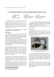
The key parameters <strong>of</strong> an involute helical gear are <strong>the</strong><br />
number z <strong>of</strong> teeth, <strong>the</strong> radius ρ <strong>of</strong> <strong>the</strong> <strong>base</strong> cylinder, <strong>the</strong><br />
<strong>base</strong> <strong>helix</strong> <strong>angle</strong> β b , and <strong>the</strong> <strong>base</strong> transverse tooth<br />
thickness s b . All <strong>the</strong>se parameters, with <strong>the</strong> exception <strong>of</strong> z,<br />
are shown in Fig. 1. (Regardless <strong>of</strong> <strong>the</strong> actual radial extent<br />
<strong>of</strong> <strong>the</strong> tooth flanks, <strong>the</strong> involute helicoids <strong>of</strong> a tooth are<br />
shown in Fig. 1 as extending inwards up to <strong>the</strong> <strong>base</strong><br />
cylinder.)<br />
Quantities such as <strong>the</strong> transverse and normal modules m<br />
and m n , <strong>the</strong> transverse and normal pressure <strong>angle</strong>s α and<br />
α n , etc. ([8], [9]), do not directly characterize <strong>the</strong> gear.<br />
Ra<strong>the</strong>r, <strong>the</strong>y refer to both <strong>the</strong> rack cutter that is ideally<br />
able to generate <strong>the</strong> gear, and <strong>the</strong> setting <strong>of</strong> such a tool<br />
relative to <strong>the</strong> gear being cut. Because infinitely many<br />
rack cutters can be used to generate <strong>the</strong> same gear, none <strong>of</strong><br />
<strong>the</strong>m should be bestowed, in principle, with <strong>the</strong> role <strong>of</strong><br />
characterizing <strong>the</strong> gear. Despite this, and due to <strong>the</strong><br />
existence <strong>of</strong> series <strong>of</strong> normalized normal modules [10] and<br />
commonly-selected values <strong>for</strong> <strong>the</strong> pressure <strong>angle</strong> <strong>of</strong> rack<br />
cutters, <strong>the</strong> attempt will be shown fur<strong>the</strong>r on to single out<br />
<strong>the</strong> possible rack cutter with normalized parameters that is<br />
1
12th <strong>IFToMM</strong> World Congress, Besançon, June 18-21, 2007 406<br />
As is known, <strong>the</strong> span measurement is feasible only if <strong>the</strong><br />
width L <strong>of</strong> <strong>the</strong> gear satisfies <strong>the</strong> following inequality<br />
L > W sin β<br />
(5)<br />
k<br />
b<br />
s b<br />
capable <strong>of</strong> generating an involute gear characterized by a<br />
given set <strong>of</strong> values <strong>for</strong> z, ρ, β b , and s b .<br />
Additional geometric parameters such as tip diameter,<br />
root diameter, etc., will be disregarded in this paper.<br />
A. The span measurement<br />
The span (or Wildhaber) measurement W k <strong>of</strong> an external<br />
helical involute gear as a function <strong>of</strong> <strong>the</strong> basic geometric<br />
parameters <strong>of</strong> <strong>the</strong> gear is provided by ([1]-[8])<br />
( 1)<br />
W = k − p + s<br />
(1)<br />
k bn bn<br />
where k is <strong>the</strong> number <strong>of</strong> gear teeth interposed between<br />
<strong>the</strong> disc anvils <strong>of</strong> <strong>the</strong> micrometer; p bn is <strong>the</strong> normal <strong>base</strong><br />
pitch <strong>of</strong> <strong>the</strong> gear ([8]), i.e., <strong>the</strong> distance – measured on <strong>the</strong><br />
<strong>base</strong> cylinder – between <strong>the</strong> <strong>base</strong> helices <strong>of</strong> homologous<br />
involute helicoids <strong>of</strong> two adjacent teeth (it is also <strong>the</strong><br />
linear distance between <strong>the</strong> a<strong>for</strong>ementioned involute<br />
helicoids); and s bn is <strong>the</strong> <strong>base</strong> normal thickness <strong>of</strong> a tooth,<br />
i.e., <strong>the</strong> distance – measured on <strong>the</strong> <strong>base</strong> cylinder –<br />
between <strong>the</strong> two <strong>base</strong> helices <strong>of</strong> <strong>the</strong> same tooth. Quantity<br />
p bn is related to <strong>the</strong> transverse <strong>base</strong> pitch p b by <strong>the</strong><br />
following condition ([8])<br />
p = p cos β<br />
(2)<br />
bn b b<br />
where p b is obviously given by<br />
p b<br />
2 π ρ<br />
= (3)<br />
z<br />
Similarly, <strong>the</strong> relationship between <strong>the</strong> <strong>base</strong> normal<br />
thickness s bn and <strong>the</strong> transverse normal thickness s b is<br />
s<br />
ρ<br />
β b<br />
Fig. 1. Key parameters <strong>of</strong> an involute helical gear.<br />
= s cos β (4)<br />
bn b b<br />
B. The overpin measurement<br />
For <strong>the</strong> measurement over pins (or balls), <strong>the</strong> distance e<br />
<strong>of</strong> <strong>the</strong> pin axes (ball centers) from <strong>the</strong> gear axis is related<br />
to <strong>the</strong> measured value F a by <strong>the</strong> ensuing condition ([1]-<br />
[4], [8], [9])<br />
Fa<br />
m a<br />
e =<br />
⎡π<br />
⎛ z ⎞⎤<br />
2sin ⎢ int ⎜ ⎟<br />
z 2 ⎥<br />
⎣ ⎝ ⎠⎦<br />
where a is <strong>the</strong> diameter <strong>of</strong> both pins (balls) and int(.) is <strong>the</strong><br />
function that returns <strong>the</strong> integer part <strong>of</strong> its argument. In<br />
Eq. (6) and in <strong>the</strong> sequel <strong>of</strong> this subsection, <strong>the</strong> upper or<br />
lower sign has to be used depending on whe<strong>the</strong>r <strong>the</strong> gear<br />
is external or, respectively, internal.<br />
In turn, quantity e depends both on <strong>the</strong> basic geometric<br />
parameters <strong>of</strong> <strong>the</strong> inspected gear and on <strong>the</strong> pin diameter<br />
according to <strong>the</strong> following expression<br />
(6)<br />
ρ<br />
e = (7)<br />
cosϑ<br />
In Eq. (7) <strong>angle</strong> ϑ is implicitly provided by<br />
⎛ sbn<br />
+ a π ⎞<br />
invϑ<br />
= ± ⎜ − ⎟<br />
⎝ 2ρ<br />
cos βb<br />
z ⎠<br />
Function inv(.) appearing in Eq. (8) is defined by<br />
(8)<br />
inv u = tan u − u<br />
(9)<br />
In evaluating <strong>the</strong> right-hand side <strong>of</strong> Eq. (9), <strong>angle</strong> u has to<br />
be expressed in radians.<br />
III. The three <strong>measuring</strong> <strong>technique</strong>s<br />
This section will briefly review <strong>the</strong> existing <strong>measuring</strong><br />
<strong>technique</strong> [7] and presents <strong>the</strong> new ones. All three<br />
<strong>technique</strong>s will be explained by referring to external<br />
gears, though <strong>the</strong> last one is suitable <strong>for</strong> internal gears too.<br />
A. Two span measurement and one overpin measurements<br />
Once it has been recognized that <strong>the</strong> fundamental<br />
geometric parameters <strong>of</strong> an involute gear are four (z, ρ, β b ,<br />
and s b , or equivalently – thanks to Eq. (4) – z, ρ, β b , and<br />
s bn ) it is a matter <strong>of</strong> course that three distinct<br />
measurements are necessary – in addition to <strong>the</strong> count <strong>of</strong><br />
<strong>the</strong> number z <strong>of</strong> teeth – in order to identify a gear.<br />
According to <strong>the</strong> procedure presented in [7], two span<br />
measurements have to be taken with different values <strong>of</strong> k,<br />
<strong>for</strong> instance, k and k + 1 . These two measurements allow<br />
linear determination <strong>of</strong> quantities p bn and s bn ([4], see also<br />
Eqs. (1))<br />
2
12th <strong>IFToMM</strong> World Congress, Besançon, June 18-21, 2007 406<br />
p = W − W<br />
(10)<br />
bn k + 1 k<br />
( 1) 1<br />
sbn k W k W<br />
k k +<br />
= − − (11)<br />
Quantity s bn is one <strong>of</strong> <strong>the</strong> four elemental parameters <strong>of</strong><br />
<strong>the</strong> gear. As <strong>for</strong> p bn , its known value is instrumental in<br />
laying down an equation in <strong>the</strong> remaining unknown<br />
parameters, i.e., ρ and β b . By merging Eqs. (2) and (3), <strong>the</strong><br />
ensuing condition is obtained<br />
z pbn<br />
ρ cos βb<br />
= (12)<br />
2 π<br />
whose right-hand side has to be considered as known (Eq.<br />
(10)).<br />
The last <strong>of</strong> <strong>the</strong> required measurements is <strong>the</strong> overpin<br />
measurement F a , taken with pins <strong>of</strong> known diameter a.<br />
This measurement results in a value <strong>for</strong> parameter e (see<br />
Eq. (6)). An equation set composed <strong>of</strong> Eqs. (7), (8), and<br />
(12) can now be considered that has ρ, β b , and ϑ as<br />
unknowns. Insertion <strong>of</strong> expression (12) <strong>for</strong> ρ cosβ b into<br />
Eq. (8) leads to<br />
π ⎛ sbn<br />
+ a ⎞<br />
invϑ<br />
= ⎜ − 1⎟<br />
z ⎝ pbn<br />
⎠<br />
(13)<br />
All quantities on <strong>the</strong> right-hand side <strong>of</strong> Eq. (13) are known<br />
a priori (pin or ball diameter a), or have already been<br />
determined (z, s bn , and p bn ). There<strong>for</strong>e Eq. (13) – which<br />
has a classical <strong>for</strong>m in involutometry – can be solved <strong>for</strong><br />
unknown ϑ by a numeric iterative algorithm (bisection,<br />
Newton-Raphson, etc.).<br />
Once <strong>the</strong> value <strong>of</strong> ϑ has been determined, Eq. (7)<br />
linearly yields <strong>the</strong> value <strong>of</strong> ρ<br />
ρ = ecosϑ<br />
(14)<br />
Finally <strong>the</strong> <strong>base</strong> <strong>helix</strong> <strong>angle</strong> β b can be found via Eq. (12)<br />
−1<br />
⎛ z pbn<br />
⎞<br />
βb<br />
= cos ⎜ ⎟<br />
⎝ 2 π ρ ⎠<br />
(15)<br />
This concludes determination <strong>of</strong> <strong>the</strong> four basic<br />
parameters <strong>of</strong> <strong>the</strong> inspected gear, i.e., z, ρ, β b , and s bn . If s b<br />
is <strong>of</strong> interest instead <strong>of</strong> s bn , <strong>the</strong>n Eq. (4) simply allows<br />
such a replacement.<br />
B. One span measurement and two overpin measurements<br />
The first <strong>of</strong> <strong>the</strong> proposed new <strong>technique</strong>s is presented<br />
hereafter.<br />
As soon as <strong>the</strong> outcome <strong>of</strong> one span measurements W k<br />
and two overpin measurements F a1 and F a2 are available,<br />
it is possible to lay down <strong>the</strong> following set <strong>of</strong> six<br />
equations (see Eqs. (1), (12), (13), and (7))<br />
( 1)<br />
⎧Wk = k − pbn + sbn<br />
⎪<br />
⎪<br />
z pbn<br />
ρ cos βb<br />
=<br />
⎪ 2 π<br />
⎪<br />
⎪ π ⎛ sbn<br />
+ a ⎞<br />
1<br />
invϑ1<br />
= − 1<br />
⎪ ⎜ ⎟<br />
z ⎝ pbn<br />
⎠<br />
⎪<br />
⎨ π ⎛ sbn<br />
+ a ⎞<br />
2<br />
⎪invϑ2<br />
= ⎜ − 1⎟<br />
⎪ z ⎝ pbn<br />
⎠<br />
⎪ ρ<br />
⎪cosϑ1<br />
=<br />
⎪ e1<br />
⎪ ρ<br />
⎪cosϑ2<br />
=<br />
⎪⎩ e2<br />
where quantities e i (i=1,2) are given by (see Eq. (6))<br />
Fai<br />
− ai<br />
ei<br />
= =<br />
⎡π<br />
⎛ z ⎞⎤<br />
2sin ⎢ int ⎜ ⎟<br />
z 2 ⎥<br />
⎣ ⎝ ⎠⎦<br />
( i 1,2 )<br />
(16)<br />
(17)<br />
In Eq. (17), a 1 and a 2 are <strong>the</strong> known diameters <strong>of</strong> <strong>the</strong> first<br />
and second pairs <strong>of</strong> identical pins (or balls). Equation set<br />
(16) has six unknowns, namely, p bn , s bn , ρ, β b , ϑ 1 , and ϑ 2 ,<br />
which can be determined as shown hereafter.<br />
The expression <strong>of</strong> s bn obtainable from <strong>the</strong> first <strong>of</strong> Eqs.<br />
(16) is first inserted into <strong>the</strong> third and fourth <strong>of</strong> Eqs. (16)<br />
z<br />
invϑi<br />
+ k<br />
π<br />
1<br />
= =<br />
W + a p<br />
k i bn<br />
( i 1,2 )<br />
(18)<br />
By equating <strong>the</strong> left-hand sides <strong>of</strong> Eqs. (18) <strong>for</strong> i=1 and<br />
i =2, <strong>the</strong> ensuing condition can be derived<br />
π k<br />
+<br />
2<br />
inv<br />
1<br />
−<br />
k<br />
+<br />
1<br />
inv<br />
2<br />
+<br />
2<br />
−<br />
1<br />
= 0 (19)<br />
z<br />
( W a ) ϑ ( W a ) ϑ ( a a )<br />
k<br />
Now <strong>the</strong> last two <strong>of</strong> Eqs. (16) are solved <strong>for</strong> ϑ 1 and ϑ 2<br />
ϑ<br />
ρ<br />
( i )<br />
−1<br />
i<br />
= cos = 1,2 (20)<br />
ei<br />
These expressions <strong>for</strong> ϑ 1 and ϑ 2 are inserted into Eq. (19)<br />
⎛<br />
Wk<br />
+ a e − ρ − ρ cos<br />
⎝<br />
( )<br />
ρ ⎞<br />
⎟<br />
⎠<br />
2 2 −1<br />
2 ⎜ 1<br />
e1<br />
⎛<br />
− ( Wk<br />
+ a ) ⎜ e − ρ − ρ cos<br />
⎝<br />
π kρ<br />
+ ( a2 − a1<br />
) = 0<br />
z<br />
2 2 −1<br />
1 2<br />
ρ ⎞<br />
⎟<br />
e2<br />
⎠<br />
(21)<br />
Equation (21) contains <strong>the</strong> radius <strong>of</strong> <strong>the</strong> <strong>base</strong> cylinder, ρ,<br />
as only unknown, which can <strong>the</strong>re<strong>for</strong>e be determined by<br />
resorting to a numeric algorithm <strong>for</strong> solving univariate<br />
transcendental equations. Subsequently, once ϑ 1 has been<br />
computed by <strong>the</strong> first <strong>of</strong> Eqs. (20), <strong>the</strong> first <strong>of</strong> Eqs. (18)<br />
3
12th <strong>IFToMM</strong> World Congress, Besançon, June 18-21, 2007 406<br />
yields <strong>the</strong> value <strong>of</strong> p bn . Now <strong>the</strong> first two conditions in Eq.<br />
(16) can be solved <strong>for</strong> s bn and β b respectively, thus<br />
completing <strong>the</strong> identification <strong>of</strong> <strong>the</strong> geometry <strong>of</strong> <strong>the</strong><br />
inspected gear in terms <strong>of</strong> parameters z, ρ, β b , and s bn .<br />
C. Three overpin measurements<br />
The second <strong>of</strong> <strong>the</strong> proposed new <strong>technique</strong>s is explained<br />
in <strong>the</strong> following. It requires no span measurement and<br />
three overpin measurements, F a1 , F a2 , and F a3 , taken by<br />
three pairs <strong>of</strong> pins (or ball) having diameters a 1 , a 2 , and a 3 .<br />
At first, quantities e i (i=1,2,3) are obtained by Eq. (6),<br />
here re-written <strong>for</strong> <strong>the</strong> sake <strong>of</strong> clarity<br />
Fai<br />
− ai<br />
ei<br />
= =<br />
⎡π<br />
⎛ z ⎞⎤<br />
2sin ⎢ int ⎜ ⎟<br />
z 2 ⎥<br />
⎣ ⎝ ⎠⎦<br />
Rearrangement <strong>of</strong> Eq. (8) leads to<br />
( i 1,2,3)<br />
⎛ π ⎞<br />
⎜invϑi + ⎟ 2ρ cos βb − sbn − ai<br />
= 0 i = 1,2,3<br />
⎝ z ⎠<br />
( )<br />
If re-written in vector <strong>for</strong>m, Eq. (23) becomes<br />
(22)<br />
(23)<br />
⎡2ρ<br />
cos βb<br />
⎤<br />
M<br />
⎢<br />
s<br />
⎥<br />
bn<br />
= 0 (24)<br />
⎢ ⎥<br />
⎢⎣<br />
1 ⎥⎦<br />
where matrix M has <strong>the</strong> ensuing expression<br />
⎡ π<br />
⎤<br />
⎢<br />
invϑ1 + −1<br />
−a1<br />
z<br />
⎥<br />
⎢<br />
⎥<br />
π<br />
M = ⎢invϑ2 + −1<br />
−a<br />
⎥<br />
2<br />
(25)<br />
⎢ z<br />
⎥<br />
⎢<br />
π<br />
⎥<br />
⎢invϑ3 + −1<br />
−a<br />
⎥<br />
3<br />
⎢⎣<br />
z<br />
⎥⎦<br />
Equation (24) can be regarded as a homogeneous linear<br />
set <strong>of</strong> three equations that have <strong>the</strong> components <strong>of</strong> vector<br />
( s )<br />
2ρ cos β , , 1 T<br />
as unknowns. Since such a vector<br />
b<br />
bn<br />
cannot vanish − its last component is unitary − matrix M<br />
has to be singular, which implies <strong>the</strong> ensuing condition<br />
det M = 0<br />
(26)<br />
By considering Eq. (25), Eq. (26) translates into<br />
( a − a ) invϑ<br />
+ ( a − a )<br />
( a a )<br />
invϑ<br />
3 2 1 1 3 2<br />
+ − invϑ<br />
= 0<br />
2 1 3<br />
(27)<br />
At this point, <strong>the</strong> relations that corresponds to Eq. (7)<br />
are considered<br />
ϑ<br />
ρ<br />
( i )<br />
−1<br />
i<br />
= cos = 1,2,3 (28)<br />
ei<br />
By inserting expressions (28) <strong>for</strong> ϑ i (i=1,2,3) into Eq.<br />
(27), an equations that has <strong>the</strong> radius <strong>of</strong> <strong>the</strong> <strong>base</strong> cylinder,<br />
ρ, as <strong>the</strong> only unknown is obtained<br />
a − a<br />
⎛<br />
e − ρ − ρ cos<br />
⎝<br />
( )<br />
ρ ⎞<br />
⎟<br />
⎠<br />
2 2 −1<br />
3 2 ⎜ 1<br />
e1<br />
⎛<br />
+ ( a − a ) ⎜ e − ρ − ρ cos<br />
⎝<br />
2 2 −1<br />
1 3 2<br />
ρ ⎞<br />
⎟<br />
e2<br />
⎠<br />
⎛ 2 2 −1<br />
ρ ⎞<br />
+ ( a2 − a1 ) ⎜ e3<br />
− ρ − ρ cos ⎟ = 0<br />
⎝<br />
e3<br />
⎠<br />
(29)<br />
Once <strong>the</strong> value <strong>of</strong> ρ that satisfies Eq. (29) has been<br />
found by a numeric algorithm, its replacement into Eq.<br />
(28) leads to determination <strong>of</strong> <strong>angle</strong>s ϑ i (i=1,2,3). Now M<br />
(Eq. (25)) can be considered as a singular matrix<br />
composed <strong>of</strong> numbers (see Eq. (26)), and Eq. (24) can be<br />
regarded as an over-constrained set <strong>of</strong> three nonhomogeneous<br />
linearly-dependent equations in two<br />
unknowns, namely, quantities 2ρ cosβ b and s bn . These can<br />
be linearly determined by considering only two <strong>of</strong> <strong>the</strong><br />
three conditions embedded into Eq. (24). As soon as <strong>the</strong><br />
value <strong>of</strong> 2ρ cosβ b has been found, determining β b is a<br />
trivial task (ρ is already known). This concludes<br />
identification <strong>of</strong> <strong>the</strong> basic geometry <strong>of</strong> <strong>the</strong> inspected<br />
helical involute gear in terms <strong>of</strong> parameters z, ρ, β b , and<br />
s bn .<br />
Differently from <strong>the</strong> previous two <strong>technique</strong>s, this last<br />
<strong>technique</strong> is also applicable to external helical gear whose<br />
width is too small <strong>for</strong> Eq. (5) to be satisfied <strong>for</strong> one or two<br />
values <strong>of</strong> k (second and first <strong>technique</strong> respectively).<br />
Moreover, it is <strong>the</strong> only <strong>technique</strong> out <strong>of</strong> <strong>the</strong> three dealt<br />
with in this paper that can be applied to internal helical<br />
involute gears, provided that balls are used instead <strong>of</strong><br />
rollers and Eqs. (22), (23), and (25) are suitably modified<br />
to incorporate <strong>the</strong> choice <strong>of</strong> <strong>the</strong> lower signs in Eqs. (6) and<br />
(8).<br />
IV. Remarks<br />
A. Determining <strong>the</strong> customary gear parameters<br />
A few comment are provided hereafter about some<br />
auxiliary parameters commonly mentioned while<br />
describing <strong>the</strong> geometry <strong>of</strong> a gear. These parameters do<br />
not add on to <strong>the</strong> in<strong>for</strong>mation yielded by <strong>the</strong> four basic<br />
parameters previously determined, i.e., z, ρ, β b , and s bn .<br />
Ra<strong>the</strong>r, <strong>the</strong>y translate <strong>the</strong> already-available knowledge<br />
about <strong>the</strong> geometry <strong>of</strong> <strong>the</strong> inspected gear into data on <strong>the</strong><br />
geometry and <strong>the</strong> setting <strong>of</strong> <strong>the</strong> rack cutter that has (or<br />
might have) been used to generate <strong>the</strong> gear.<br />
Any involute gear has in common <strong>the</strong> normal <strong>base</strong><br />
pitch, p bn , with any o<strong>the</strong>r gear or cutting tool – hob, pinion<br />
cutter, rack cutter, etc. – able to mesh with it. For <strong>the</strong><br />
inspected gear, quantity p bn can be computed by first<br />
determining p b via Eq. (3) and inserting its value into Eq.<br />
(2). In turn, p bn depends on <strong>the</strong> pitch, π m n , <strong>of</strong> <strong>the</strong> rack<br />
4
12th <strong>IFToMM</strong> World Congress, Besançon, June 18-21, 2007 406<br />
cutter that is potentially able to generate <strong>the</strong> gear ([8])<br />
p<br />
= π m cosα<br />
(30)<br />
bn n n<br />
Quantities m n and α n appearing in Eq. (30) are, as is<br />
known, <strong>the</strong> module and <strong>the</strong> pressure <strong>angle</strong> <strong>of</strong> <strong>the</strong> rack<br />
cutter. Despite <strong>the</strong> existence <strong>of</strong> infinite pairs <strong>of</strong> values <strong>for</strong><br />
m n and α n that satisfy Eq. (30), <strong>the</strong>re is <strong>the</strong> chance that <strong>the</strong><br />
inspected gear has been obtained by a cutter that has<br />
normalized dimensions. Should this be <strong>the</strong> case, m n and α n<br />
can be identified after a few attempts (generally is α n =20°,<br />
less frequently-used values being 14.5°, 15°, 17°, 22.5°,<br />
25°, and 30°; <strong>the</strong> series <strong>of</strong> normalized values <strong>of</strong> m n is<br />
traceable in standardization tables [10]).<br />
Once m n and α n have been singled out, it is possible to<br />
complement <strong>the</strong> auxiliary in<strong>for</strong>mation on <strong>the</strong> inspected<br />
gear by computing <strong>the</strong> two setting parameters <strong>of</strong> <strong>the</strong> rack<br />
cutter with respect to <strong>the</strong> gear, namely, <strong>the</strong> cutting <strong>helix</strong><br />
<strong>angle</strong> β and <strong>the</strong> pr<strong>of</strong>ile shift x. The <strong>for</strong>mer is <strong>the</strong> <strong>angle</strong><br />
between <strong>the</strong> generators <strong>of</strong> <strong>the</strong> teeth <strong>of</strong> <strong>the</strong> rack cutter and<br />
<strong>the</strong> axis <strong>of</strong> <strong>the</strong> gear, whereas <strong>the</strong> latter is <strong>the</strong> distance (with<br />
sign) between two parallel planes fixed to <strong>the</strong> rack cutter:<br />
one is <strong>the</strong> reference plane <strong>of</strong> <strong>the</strong> rack (i.e., <strong>the</strong> plane on<br />
which <strong>the</strong> thickness <strong>of</strong> <strong>the</strong> rack teeth matches <strong>the</strong> width <strong>of</strong><br />
<strong>the</strong> rack tooth spaces), whereas <strong>the</strong> o<strong>the</strong>r is <strong>the</strong> plane that<br />
rolls − while <strong>the</strong> gear is being generated by <strong>the</strong> rack cutter<br />
− on an ideal cylinder coaxial with <strong>the</strong> gear.<br />
Angle β is implicitly given by ([8])<br />
sin βb<br />
sin β = (31)<br />
cosα<br />
The pr<strong>of</strong>ile shift x can be obtained by ([8])<br />
sbn<br />
⎛ π ⎞<br />
− m cosα<br />
⎜ + z invα<br />
⎟<br />
cos βb<br />
⎝ 2 ⎠<br />
x = (32)<br />
2 sinα<br />
where m (<strong>the</strong> transverse module) and α (<strong>the</strong> so-called<br />
transverse pressure <strong>angle</strong>) are given by ([8])<br />
m n<br />
n<br />
m = (33)<br />
cos β<br />
sinαn<br />
sinα<br />
= (34)<br />
cos β<br />
b<br />
At this point it is left to <strong>the</strong> reader <strong>the</strong> final choice on<br />
whe<strong>the</strong>r to identify a helical involute gear by four<br />
parameters (z, ρ, β b , s bn ) or five parameters (z, m n , α n , β,<br />
x). In favor <strong>of</strong> <strong>the</strong> four-parameter choice is <strong>the</strong> one-to-one<br />
correspondence between sets <strong>of</strong> parameters and gears,<br />
whereas infinitely-many five-parameter sets identify <strong>the</strong><br />
same gear. The only real advantage <strong>of</strong> <strong>the</strong> five-parameter<br />
choice is <strong>the</strong> explicit reference to <strong>the</strong> geometry and setting<br />
<strong>of</strong> a rack cutter by which <strong>the</strong> gear can be obtained.<br />
Although such a rack cutter is one out <strong>of</strong> <strong>the</strong> infinitelymany<br />
that are apt to generate <strong>the</strong> gear, most frequently it<br />
is also <strong>the</strong> only one characterized by normalized values <strong>of</strong><br />
m n and α n .<br />
B. Accuracy issues and limitations<br />
The three <strong>technique</strong>s described in section III all lay on<br />
rigorous grounds and would result in <strong>the</strong> same outcome if<br />
applied to a perfect helical involute gear. Despite this, in<br />
practice <strong>the</strong> accuracy <strong>of</strong> <strong>the</strong>ir results tends to decrease<br />
from <strong>the</strong> first to <strong>the</strong> third <strong>technique</strong>. The reason is mainly<br />
due to potential ill-conditioning <strong>of</strong> <strong>the</strong> set <strong>of</strong> equations to<br />
be solved: if two overpin measurements <strong>of</strong> <strong>the</strong> same gear<br />
were executed with two pairs <strong>of</strong> pins whose diameters<br />
differs only slightly, <strong>the</strong> minuscule geometric difference<br />
detectable, in principle, by <strong>the</strong> two measurements would<br />
be almost completely masked by <strong>the</strong> finite accuracy that<br />
affects <strong>the</strong> adopted <strong>measuring</strong> instrument, so that<br />
inaccurate results would be obtained. There<strong>for</strong>e, if two or<br />
more overpin measurements <strong>of</strong> a gear are required, care<br />
must be paid in selecting as far apart from each o<strong>the</strong>r as<br />
possible <strong>the</strong> diameters <strong>of</strong> different pairs <strong>of</strong> pins, still<br />
preserving <strong>the</strong> correct contact between <strong>the</strong> pins and <strong>the</strong><br />
portion <strong>of</strong> involute helicoids on <strong>the</strong> tooth flanks (to this<br />
end, <strong>the</strong> pins with <strong>the</strong> smallest diameter could be flattened<br />
in order to make <strong>the</strong>m reach <strong>the</strong> inner part <strong>of</strong> <strong>the</strong> involute<br />
helicoids while avoiding contact with <strong>the</strong> root cylinder <strong>of</strong><br />
<strong>the</strong> gear). As a rule, if more than one <strong>technique</strong> is<br />
applicable to <strong>the</strong> case at hand, preference should be<br />
granted to <strong>the</strong> <strong>technique</strong> that requires <strong>the</strong> lowest number<br />
<strong>of</strong> overpin measurements.<br />
All three methods described in <strong>the</strong> previous section are<br />
expected to show a declining accuracy as <strong>the</strong> <strong>base</strong> <strong>helix</strong><br />
<strong>angle</strong> β b approaches zero. Should this occur, a small error<br />
affecting <strong>the</strong> argument <strong>of</strong> <strong>the</strong> cos −1 function on <strong>the</strong> righthand<br />
side <strong>of</strong> Eq. (15) would translate into a great<br />
uncertainty about <strong>the</strong> cos −1 value. Fortunately, involute<br />
helical gears that are almost spur gears are quite<br />
uncommon, and <strong>the</strong> limitation just outlined is seldom<br />
relevant.<br />
In any case, even in <strong>the</strong> most favousable conditions, <strong>the</strong><br />
accuracy associated to <strong>the</strong> value <strong>of</strong> β b assessed by any <strong>of</strong><br />
<strong>the</strong> explained procedures is no match <strong>for</strong> <strong>the</strong> higher<br />
accuracy attainable by state-<strong>of</strong>-<strong>the</strong>-art gear inspection<br />
apparatuses. These are equipped with <strong>measuring</strong> devices<br />
that are more precise than 0.01 mm-accurate micrometers,<br />
and can make <strong>the</strong>ir feeler run along <strong>the</strong> full span L <strong>of</strong> <strong>the</strong><br />
gear width in order to accurately determine <strong>the</strong> lead <strong>of</strong> <strong>the</strong><br />
helicoidal tooth flanks. Never<strong>the</strong>less <strong>the</strong> proposed<br />
inspection method proves valuable whenever special<br />
checking equipment is unavailable or unjustified.<br />
The three <strong>technique</strong>s dealt with in this paper are not<br />
applicable to spur gears (β b = 0). In case <strong>the</strong> radius ρ <strong>of</strong><br />
<strong>the</strong> <strong>base</strong> cylinder and <strong>the</strong> <strong>base</strong> tooth thickness s b <strong>of</strong> a spur<br />
gear have to be assessed, <strong>the</strong> three presented <strong>technique</strong>s<br />
should be modified so as to drop one overpin<br />
measurement from each <strong>of</strong> <strong>the</strong>m. For instance, <strong>the</strong> three<br />
5
12th <strong>IFToMM</strong> World Congress, Besançon, June 18-21, 2007 406<br />
span measurement <strong>technique</strong> reported in [7] would<br />
trans<strong>for</strong>m into <strong>the</strong> <strong>the</strong> span measurement procedure<br />
explained in [4] and [5] <strong>for</strong> determining parameters ρ and<br />
s bn (see Eqs. (10)-(12)). Detailed description <strong>of</strong> how <strong>the</strong><br />
remaining two <strong>technique</strong>s should be specialized <strong>for</strong> spur<br />
gears is beyond <strong>the</strong> scope <strong>of</strong> this paper.<br />
V. Numerical example<br />
Application <strong>of</strong> <strong>the</strong> third procedure explained in section<br />
III is here shown with reference to an external involute<br />
helical gear that, upon inspection, has provided <strong>the</strong><br />
following measured data<br />
F<br />
F<br />
F<br />
z = 31<br />
3<br />
4.5<br />
6<br />
= 89.91 mm<br />
= 95.57 mm<br />
= 100.56 mm<br />
(35)<br />
It is hypo<strong>the</strong>sized that <strong>the</strong> three measurements over<br />
balls, F 3 , F 4.5 , and F 6 are taken by standard handheld<br />
micrometers, whose accuracy is usually 0.01 mm. The<br />
three pairs <strong>of</strong> balls are characterized by <strong>the</strong> following<br />
diameters: a 1 =3.000 mm, a 2 =4.500 mm, and a 3 =6.000<br />
mm.<br />
The values <strong>of</strong> e i (i=1,2,3) provided by Eq. (22) are<br />
e = 43.5108 mm<br />
1<br />
e = 45.5935 mm<br />
2<br />
e = 47.3408 mm<br />
3<br />
(36)<br />
(Irrespectively <strong>of</strong> <strong>the</strong> accuracy affecting <strong>the</strong> input data,<br />
intermediate and final results are here expressed by four<br />
decimal digits in order to allow <strong>the</strong> reader to thoroughly<br />
check <strong>the</strong> reported computations.)<br />
Equation (29) is satisfied by <strong>the</strong> following root<br />
ρ = 40.7512 mm<br />
(37)<br />
Finally, linear solution <strong>of</strong> equation set (24) leads to <strong>the</strong><br />
remaining two basic parameters <strong>of</strong> <strong>the</strong> considered gear<br />
β = 26.5641 deg<br />
(38)<br />
b<br />
s = 5.5636 mm<br />
(39)<br />
bn<br />
As already pointed out, <strong>the</strong> value <strong>of</strong> z (Eq. (35)),<br />
toge<strong>the</strong>r with <strong>the</strong> values <strong>of</strong> parameters ρ, β b , and s bn (Eqs.<br />
(37)-(39)) completely define <strong>the</strong> basic geometry <strong>of</strong> <strong>the</strong><br />
inspected gear (i.e., <strong>the</strong> shape <strong>of</strong> <strong>the</strong> involute helicoids and<br />
<strong>the</strong>ir spacing around <strong>the</strong> <strong>base</strong> cylinder). Alternatively,<br />
parameter s bn can be replaced by parameter s b (see Eq. (4))<br />
s = 6.2202 mm<br />
(40)<br />
b<br />
Now <strong>the</strong> attempt will be made <strong>of</strong> estimating <strong>the</strong><br />
ancillary parameters m n , α n , β, and x. For <strong>the</strong> value <strong>of</strong> p bn<br />
provided by Eqs. (3) and (2), by also presuming α n = 20°,<br />
Eq. (30) yields<br />
m = 2.5025 mm<br />
(41)<br />
n<br />
which is very close to <strong>the</strong> normalized value m n = 2.5 mm<br />
([10]). It is <strong>the</strong>re<strong>for</strong>e reasonable to consider <strong>the</strong> inspected<br />
gear as characterized by α n = 20° and m n = 2.5 mm.<br />
Based on Eq. (31), <strong>the</strong> value <strong>of</strong> β is determined<br />
β = 28.4179°<br />
(42)<br />
Finally, Eq. (32) yields <strong>the</strong> value <strong>of</strong> <strong>the</strong> pr<strong>of</strong>ile shift x<br />
VI. Conclusion<br />
x = 0.4464 mm<br />
(43)<br />
The paper has presented two new and easy-toimplement<br />
methods applicable to a helical involute gear<br />
<strong>for</strong> <strong>measuring</strong> its basic geometric parameters and, among<br />
<strong>the</strong>se, <strong>the</strong> <strong>base</strong> <strong>helix</strong> <strong>angle</strong>. Similarly to an already known<br />
procedure, <strong>the</strong> proposed methods require taking two or<br />
three measurements over pins, toge<strong>the</strong>r with one or no<br />
span measurement respectively. Common micrometers<br />
with standard and disc anvils, toge<strong>the</strong>r with pairs <strong>of</strong><br />
calibrated rollers or balls, are <strong>the</strong> only needed inspection<br />
equipment.<br />
Differently from <strong>the</strong> already known method, one <strong>of</strong> <strong>the</strong><br />
proposed methods can be applied to internal helical<br />
involute gears too.<br />
A numerical example has shown application <strong>of</strong> one <strong>of</strong><br />
<strong>the</strong> presented <strong>technique</strong>s to a case study.<br />
References<br />
[1] Townsend, D.P., Dudley’s Gear Handbook, McGraw-Hill, New<br />
York, ISBN 0-07-017903-4, 1992.<br />
[2] Henriot, G., Traité théorique ed pratique des engranages.<br />
Fabrication, contrôle, lubrification, traitement <strong>the</strong>rmique, Dunod,<br />
Paris, 1972.<br />
[3] Gear Design, Manufacturing and Inspection Manual, SAE,<br />
Warrendale, PA, vol. AE-15, ISBN 1-56091-006-2, 1990.<br />
[4] MAAG Gear Book, MAAG Gear-Wheel Company LTD., Zurich,<br />
Switzerland, Zurich, 1963.<br />
[5] Thoen, R.L., Measuring Pr<strong>of</strong>ile and Base Pitch Errors with a<br />
Micrometer, Gear Technology, pp. 42-45, Sept./Oct., 2002.<br />
[6] Thoen R.L., Measuring Base Helix Error on a Sine Bar, Gear<br />
Technology, pp. 25-27, July/Aug, 2001.<br />
[7] Regalado I. and Lopez R., Reverse Engineering <strong>of</strong> Pure Involute<br />
Cylindrical Gears Using Conventional Measurement Tools, Gear<br />
Technology, pp. 32-35, Jan./Feb., 2000.<br />
[8] Colbourne, J.R., The Geometry <strong>of</strong> Involute Gears, Springer-Verlag,<br />
New York, ISBN 0-387-96522-X, 1987.<br />
[9] Litvin, F.L. and Fuentes, A., Gear Geometry and Applied Theory,<br />
Cambridge University Press, ISBN 0-321- 81517-7, 2004.<br />
[10] Cylindrical gears <strong>for</strong> general engineering and <strong>for</strong> heavy<br />
engineering - Modules , Standard ISO 54:1996, 1996.<br />
6