ABB SMARTTRANSMITTERS 624 - IHB International
ABB SMARTTRANSMITTERS 624 - IHB International
ABB SMARTTRANSMITTERS 624 - IHB International

Create successful ePaper yourself
Turn your PDF publications into a flip-book with our unique Google optimized e-Paper software.
Postbus 17<br />
7480 AA Haaksbergen<br />
E-mail: ihb@ihbinternational.nl<br />
Tel. + 31 (0)53 57 431 43<br />
Mob. + 31 (0)63 01 548 26<br />
Fax + 31 (0)84 87 266 72<br />
BTW nr. 1014.51.556.B.02<br />
Bank: 47.68.92.716<br />
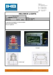
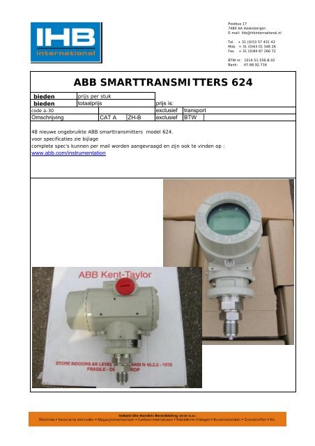
<strong>ABB</strong> <strong>SMARTTRANSMITTERS</strong> <strong>624</strong><br />
bieden prijs per stuk<br />
bieden totaalprijs prijs is:<br />
code a-30 exclusief transport<br />
Omschrijving CAT A ZH-B exclusief BTW<br />
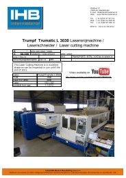
48 nieuwe ongebruikte <strong>ABB</strong> smarttransmitters model <strong>624</strong>.<br />
voor specificaties zie bijlage<br />
complete spec's kunnen per mail worden aangevraagd en zijn ook te vinden op :<br />
www.abb.com/instrumentation
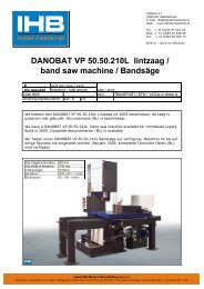
Specification sheet<br />
600T EN Series Pressure Transmitters<br />
Model <strong>624</strong>EG Gauge<br />
Model <strong>624</strong>EA Absolute<br />
Base accuracy : ± 0.075%<br />
Reliable inductive sensing system coupled<br />
with the very latest digital technologies<br />
- ensures high performance at all process conditions<br />
Wide selection of materials and choice of fill<br />
fluids including "process-inert"<br />
- meet virtually all process requirements also<br />
protecting application integrity<br />
HART 4-20 mA, Profibus PA, FF versions<br />
with plug-and-play electronics replacement<br />
- provides interchangeability for upgrading<br />
transmitter<br />
Local snap calibration and full management<br />
via hand terminal or PC-running software<br />
HART®, Profibus PA, FF communications<br />
- allows integration with standard process bus<br />
CoMeter display option<br />
- offers HART Configuration capabilities<br />
combined with local indication<br />
The all new 600T Series transmitter<br />
The first choice pressure transmitter is<br />
now an even bigger choice<br />
Ecoefficient life cycle<br />
-ensures low environmental impact in<br />
compliance with LCA assessment to ISO<br />
14040 standard<br />
1
FUNCTIONAL SPECIFICATIONS<br />
Range and span limits<br />
Sensor<br />
code<br />
D<br />
E<br />
F<br />
W<br />
U<br />
S<br />
Upper<br />
Range<br />
Limit (URL)<br />
160 kPa<br />
1600 mbar<br />
642 inH2O<br />
600 kPa<br />
6 bar<br />
87 psi<br />
2400 kPa<br />
24 bar<br />
348 psi<br />
8000 kPa<br />
80 bar<br />
1160 psi<br />
16000 kPa<br />
160 bar<br />
2320 psi<br />
42000 kPa<br />
420 bar<br />
6090 psi<br />
Span limits<br />
Maximum span = URL<br />
Minimum recommended span = URL/TD extended<br />
(can be further turndown to URL/TD maximum at no<br />
stated performances)<br />
Zero suppression and elevation<br />
Zero and span can be adjusted to any value within the range<br />
limits detailed in the table as long as:<br />
- calibrated span ≥ minimum span<br />
Damping<br />
Selectable time constant : 0, 0.25, 0.5, 1, 2, 4, 8 or 16 sec.<br />
Volume of process chamber<br />
16 cm 3 approx (1 in 3 )<br />
Lower<br />
Range<br />
Limit (LRL)<br />
0.07 kPa abs<br />
0.7 mbar abs<br />
0.5 mmHg<br />
0.07 kPa abs<br />
0.7 mbar abs<br />
0.5 mmHg<br />
0.07 kPa abs<br />
0.7 mbar abs<br />
0.5 mmHg<br />
0.07 kPa abs<br />
0.7 mbar abs<br />
0.5 mmHg<br />
0.07 kPa abs<br />
0.7 mbar abs<br />
0.5 mmHg<br />
1 kPa abs<br />
10 mbar abs<br />
0.15 psia<br />
Turndown ratio (TD)<br />
<strong>624</strong>EG <strong>624</strong>EA<br />
Normal<br />
15<br />
15<br />
15<br />
15<br />
15<br />
10<br />
Extended<br />
Maximum<br />
Normal<br />
60 100 10<br />
60 100 10<br />
60 100 10<br />
60 100 10<br />
60 100 10<br />
20<br />
30<br />
10<br />
Extended<br />
20<br />
20<br />
20<br />
20<br />
20<br />
20<br />
Maximum<br />
60<br />
60<br />
60<br />
60<br />
60<br />
30<br />
Temperature limits °C (°F) :<br />
• Ambient (is the operating temperature)<br />
Filling Model <strong>624</strong>EG Model <strong>624</strong>EA<br />
Silicone oil<br />
Inert<br />
KTFILL-1<br />
-40 and +85<br />
(-40 and +185)<br />
-20 and +85<br />
(-4 and +185)<br />
-40 and +85<br />
(-40 and +185)<br />
-40 and +85<br />
(-40 and +185)<br />
-10 and +65<br />
(+14 and +150)<br />
-10 and +85<br />
(+14 and +185)<br />
Lower ambient limit for LCD indicators: -20°C (-4°F)<br />
Upper ambient limit for CoMeter : +70°C (+158°F)<br />
• Process (1)<br />
Lower limit<br />
- refer to lower ambient limits<br />
Upper limit<br />
- Silicone oil and KTFILL-1 filling : 120°C (248°F) (2)<br />
- Inert fluid filling : 100°C (212°F) (3)<br />
(1) Process temperature above 85°C (185 °F) requires derating the<br />
ambient limits by 1.5 : 1 ratio.<br />
(2) 100°C (212°F) for application below atmospheric pressure<br />
(3) 65°C (150°F) for application below atmospheric pressure<br />
• Storage<br />
Lower limit : -50°C (-58°F); -40°C (-40°F) for LCD indicators<br />
Upper limit : +120°C (+248°F); +85°C (+185°F) for LCD indicators<br />
Overpressure limits (without damage to the transmitter)<br />
• Lower : 0.07 kPa abs, 0.7 mbar abs, 0.5 mmHg<br />
(double the value with inert filling)<br />
• Upper<br />
- sensor code D, E, F, W : 14 MPa, 140 bar, 2030 psi<br />
- sensor code U : 25 MPa, 250 bar, 3620 psi<br />
- sensor code S : 65 MPa, 650 bar, 9400 psi<br />
Proof pressure<br />
The transmitter meets SAMA PMC 27.1 requirements and can be<br />
exposed without leaking to line pressure of up to<br />
- 31.5 MPa, 315 bar, 4500 psi for sensor codes D, E, F, W, U<br />
- 80 MPa, 800 bar, 11600 psi for sensor code S<br />
Volumetric displacement<br />
< 0.020 cm 3 (0.0015 in 3 ) for max span.<br />
Electromagnetic compatibility (EMC)<br />
Comply with EN 50081-2 for emission and EN 50082-2 for<br />
immunity requirements and test; CE marking.<br />
Turn on time<br />
Operation within specification in less than 2 sec. with<br />
minimum damping.<br />
Insulation resistance<br />
> 100 MΩ @ 1000 Vdc (terminals to earth)<br />
2
ELECTRICAL CHARACTERISTICS AND OPTIONS<br />
• HART digital communication and 4 to 20 mA output<br />
Power Supply<br />
The transmitter operates from 10.5 to 42 Vdc with no load and<br />
is protected against reverse polarity connection (additional load<br />
allows operations over 42 Vdc).<br />
For EEx ia and intrinsically safe (FM, CSA and SAA) approval<br />
power supply must not exceed 30 Vdc.<br />
MINIMUM OPERATING VOLTAGES<br />
no link on output indicator plugs<br />
with optional output LCD indicator and surge protection<br />
with CoMeter<br />
with optional output LCD indicator<br />
with optional surge protection<br />
with optional output analog indicator<br />
with integral display<br />
(volts)<br />
10.5 10.7 12.1 12.5 13.3 14.1 14.3<br />
Load limitations - 4-20 mA and HART total loop resistance :<br />
R(kΩ) =<br />
Supply voltage - min. operating voltage (Vdc)<br />
22<br />
(ohms)<br />
1430<br />
Total loop resistance<br />
600<br />
250<br />
4 to 20 mA and<br />
HART digital communication<br />
4 to 20 mA only<br />
10.5 25 (ref.)<br />
42 (volts)<br />
Supply voltage<br />
Optional indicators<br />
• Output meter (user adjustable)<br />
- LCD : 3 1/2-digit with 10 mm (3/8 in) high, 7-segment<br />
characters. Engineering unit labels are provided. LCD<br />
output meter may be calibrated within the range -1999 to +<br />
1999 with a span adjustable between 100 and 3998 units.<br />
(Display of decimal point, if required, is switch selectable)<br />
- analog : 36 mm (1.4 in) scale on 90°<br />
• Integral display<br />
- LCD: 4-digit with 8 mm. (5/16 in) high, 9-segment alphanumeric<br />
characters.<br />
User-definable display mode with HART communication :<br />
- process variable in engineering units, or<br />
- percent of range, or<br />
- process variable in engineering units and percent of range<br />
alternating every 3 seconds, or<br />
- process variable in engineering units and digital<br />
output (4 to 20 mA) alternating every 3 seconds.<br />
Factory selectable display mode with 4 to 20 mA output :<br />
- percent of range<br />
- percent of range and 4 to 20 mA output alternating every<br />
3 seconds<br />
Display also indicates diagnostic messages.<br />
• CoMeter<br />
- 5-digit (± 99999 counts) programmable with 7.6 mm. high<br />
(3 in), 7-segment numeric characters plus sign and digital<br />
point<br />
- 10-segment bargraph display (10% per segment)<br />
- 7-digit LCD with 6 mm. high (2.3 in), 14-segment<br />
alphanumeric characters.<br />
Optional surge protection<br />
Up to 2.5 kV (5 kA discharge current) of 8 µs rise time/20 µs<br />
decay.<br />
Output signal<br />
Two-wire 4 to 20 mA dc, user-selectable for linear or square root<br />
output, power of 3/2 or 5/2, 5th order or two 2nd order switching<br />
point selectable programmable polynomial output.<br />
HART ® communication provides digital process variable (%, mA<br />
or engineering units) superimposed on 4 to 20 mA signal, with<br />
protocol based on Bell 202 FSK standard.<br />
Output current limits (to NAMUR standard)<br />
Overload condition<br />
- Lower limit : 3.8 mA dc<br />
- Upper limit : 20.8 mA dc<br />
Transmitter failure mode (to NAMUR standard)<br />
The output signal can be user-selected to a value of 3.6 or<br />
21.6 mA on gross transmitter failure condition, detected by selfdiagnostics.<br />
In case of CPU failure the output is driven 21.6 mA.<br />
3
• Profibus PA output<br />
Power supply<br />
The transmitter operates from 10.5 to 32 Vdc with no polarity.<br />
For EEx ia approval power supply must not exceed 15 Vdc.<br />
Intrinsic safety installation according to FISCO model.<br />
Current consumption<br />
- operating (quiescent) : 10.5 mA<br />
- communicating : 20.5 mA<br />
- fault current limiting : 16 mA max.<br />
Output signal<br />
Physical layer in compliance to IEC 1158-2/EN 61158-2 with<br />
transmission to Manchester II modulation, at 31.25 kbit/sec.<br />
Output interface<br />
Profibus PA communication according to Profibus DP50170<br />
Part 2/DIN 19245 part 1-3 compliant to Profiles 3.0 Class A &<br />
B for pressure transmitter.<br />
Optional indicator<br />
Integral display<br />
- LCD : 4 digit characters, displaying process variable in<br />
engineering units or as percentage value.<br />
Display also indicates diagnostic messages.<br />
Transmitter failure mode<br />
On gross transmitter failure condition, detected by self-diagnostics,<br />
the output signal can be driven to defined conditions,<br />
selectable by the user as safe, last valid or calculated value.<br />
• FOUNDATION fieldbus output<br />
Power supply<br />
The transmitter operates from 10.5 to 32 Vdc with no polarity.<br />
For EEx ia approval power supply must not exceed 24 Vdc.<br />
Intrinsic safety installation according to FF application guide<br />
Current consumption<br />
- operating (quiescent) : 10.5 mA<br />
- communicating : 20.5 mA<br />
- fault current limiting : 16 mA max.<br />
Output signal<br />
Physical layer in compliance to IEC 1158-2/EN 61158-2 with<br />
transmission to Manchester II modulation, at 31.25 kbit/sec.<br />
Output interface<br />
FOUNDATION fieldbus digital communication protocol to<br />
standard H1, compliant to specification V. 1.4.<br />
Optional indicator<br />
Integral display<br />
- LCD : 4 digit characters, displaying process variable in<br />
engineering units or as percentage value.<br />
Display also indicates diagnostic messages.<br />
Transmitter failure mode<br />
The output signal is "frozen" to the last valid value on gross<br />
transmitter failure condition, detected by self-diagnostics<br />
which also indicate a BAD conditions.<br />
If electronic failure or short circuit occur the transmitter consumption<br />
is electronically limited at a defined value (16 mA<br />
approx), for safety of the network.<br />
PERFORMANCE SPECIFICATIONS<br />
Stated at ambient temperature of 23°C ± 3K (75°F ± 5), relative<br />
humidity of 50% ±20%, atmospheric pressure, zero based range<br />
for transmitter with isolating diaphragms in AISI 316 L ss or<br />
Hastelloy and silicone oil fill or KTFILL-1 and HART digital trim<br />
values equal to 4-20 mA span end points, in linear mode.<br />
Unless otherwise specified, errors are quoted as % of span.<br />
Some performance data are affected by the actual turndown (TD)<br />
as ratio between Upper Range Limit (URL) and calibrated span.<br />
IT IS RECOMMENDED TO SELECT THE TRANSMITTER<br />
SENSOR CODE PROVIDING THE TURNDOWN VALUE AS<br />
LOWEST AS POSSIBLE TO OPTIMIZE PERFORMANCE<br />
CHARACTERISTICS.<br />
Accuracy rating<br />
% of calibrated span, including combined effects of terminal based<br />
linearity, hysteresis and repeatability.<br />
• Model <strong>624</strong>EG<br />
- ± 0.075% for TD from 1:1 to 15:1<br />
(± 0.10% for sensor code S for TD from 1:1 to 10:1 )<br />
URL<br />
- ± 0.005% x<br />
Span<br />
for TD from 15:1 to 60:1<br />
URL<br />
(± 0.01% x for sensor code S<br />
Span<br />
for TD from 10:1 to 20:1)<br />
• Model <strong>624</strong>EA<br />
- ± 0.075% for TD from 1:1 to 10:1<br />
(± 0.10% for TD for sensor code S from 1:1 to 10:1)<br />
URL<br />
- ± 0.0075% x for TD from 10:1 to 20:1<br />
Span<br />
URL<br />
(± 0.01% x for sensor code S<br />
Span<br />
for TD from 10:1 to 20:1)<br />
Optional indicators accuracy<br />
• integral display (microprocessor driven) : no error<br />
• analog output meter : ± 2% full scale deflection<br />
• LCD output meter : ± 0.1% of calibrated span ± 1 unit<br />
• CoMeter<br />
- digital : ± 0.10% of max span(16 mA) ± 1 digit<br />
- analog (bargraph) : 10%<br />
Operating influences<br />
Ambient temperature per 20 K (36°F) change between the limits<br />
of - 20°C to + 65°C (-4 to +150°F) :<br />
Model<br />
<strong>624</strong>EG<br />
<strong>624</strong>EA<br />
Sensor<br />
code<br />
D,E,F,W,U<br />
S<br />
D,E,F,W,U<br />
S<br />
for TD<br />
up to<br />
15:1<br />
10:1<br />
10:1<br />
10:1<br />
± (0.08% URL + 0.15% span)<br />
± (0.10% URL + 0.15% span)<br />
± (0.08% URL + 0.15% span)<br />
± (0.10% URL + 0.15% span)<br />
Multiply by 1.5 the above coefficients for 20 K (36°F) change between the<br />
limits of -40 to -20°C (-40 to -4°F) and of +65 to +85°C (+150 to 185°F)<br />
Optional LCD output meter ambient temperature<br />
per 1 K (1.8°F) change between the limits of -20 and +80°C<br />
(-4 and + 176°F)<br />
Total effect : ± (0.0002 x span units + 0.1) of reading.<br />
Optional CoMeter ambient temperature<br />
Total reading error per 20K (36°F) change between the ambient<br />
limits of -20 and +70°C (-4 and +158°F) :<br />
± 0.15% of max span (16 mA).<br />
4
Supply voltage<br />
Within voltage/load specified limits the total effect is less than<br />
0.005% of URL per volt.<br />
Load<br />
Within load/voltage specified limits the total effect is negligible.<br />
Radio frequency interference<br />
Total effect : less than 0.10% of span from 20 to 1000 MHz and<br />
for field strengths up to 30 V/m when tested with shielded<br />
conduit and grounding, with or without meter. Meets IEC 801.<br />
Common mode interference<br />
No effect from 100 V rms @ 50 Hz, or 50 Vdc.<br />
Series mode interference<br />
No effect from 1 V rms @ 50 Hz.<br />
Mounting position<br />
No effect.<br />
Stability<br />
± 0.15% of URL over a thirty-six-month period<br />
PHYSICAL SPECIFICATIONS<br />
(Refer to ordering information sheets for variant availability<br />
related to specific model or versions code)<br />
Materials<br />
Process isolating diaphragms (*)<br />
AISI 316 L ss, Hastelloy C276 ◊; Tantalum;<br />
Hastelloy C276 ◊ on AISI 316 L ss gasket seat.<br />
Process connection (*)<br />
AISI 316 L ss; Hastelloy C ◊.<br />
Sensor fill fluid<br />
Silicone oil (DC200) or inert fill (perfluorinated polyethers<br />
Galden ◊) or "process-inert" fill (KTFILL-1).<br />
Mounting bracket (**)<br />
Zinc plated carbon steel with chrome passivation; AISI 316 L ss.<br />
Sensor housing : AISI 316 L ss<br />
Electronic housing and covers<br />
Barrel version<br />
- Low-copper content aluminium alloy with baked epoxy finish;<br />
- AISI 316 L ss.<br />
Covers O-ring: Buna N.<br />
Local zero and span adjustments:<br />
Glass filled polycarbonate plastic (removable)<br />
Tagging<br />
AISI 316 ss data plate attached to the electronics housing.<br />
Calibration<br />
- Standard: at maximum span, zero based range, ambient<br />
temperature and pressure<br />
- Optional: at specified range and ambient conditions; or at<br />
operating temperature.<br />
Optional extras<br />
Mounting brackets<br />
For 60 mm. (2 in) pipes or wall mounting.<br />
Output indicator:<br />
plug-in rotatable type, LCD or analog.<br />
Standard LCD output meter scale is 0 to 100% linear; special<br />
linear scale to specified range and engineering unit is<br />
available.Standard analog output meter scale is 0 to 100%<br />
linear; special graduation is available.<br />
Supplemental customer tag<br />
AISI 316 ss tag fastened to the transmitter with stainless steel<br />
wire for customer's tag data up to a maximum of 56 characters<br />
and spaces on two lines for tag number and tag name, and up<br />
to a maximum of 28 characters and spaces for calibration<br />
details.<br />
Surge protection (not available with Profibus PA and FF output)<br />
Cleaning procedure for oxygen service<br />
Material traceability; manifold<br />
Environmental protection<br />
Wet and dust-laden atmospheres<br />
The transmitter is dust and sand tight and protected against<br />
immersion effects as defined by IEC 529 (1989) to IP 67 (IP 68<br />
on request) or by NEMA to 4X or by JIS to C0920<br />
Hazardous atmospheres<br />
With or without output meter/integral display<br />
INTRINSIC SAFETY/EUROPE:<br />
ATEX/BASEEFA approval<br />
EC-Type Examination Certificate no. BAS 99ATEX 1180<br />
(HART)<br />
II 1 GD T50°C, EEx ia IIC T5 (-40°C ≤ Ta ≤+40°C)<br />
T95°C, EEx ia IIC T4 (-40°C ≤ Ta ≤+85°C)<br />
(FOUNDATION Fieldbus)<br />
II 1 GD T70°C, EEx ia IIC T4 (-40°C ≤ Ta ≤+60°C)<br />
EC-Type Examination Certificate no. BAS 00ATEX 1241<br />
(PROFIBUS-PA)<br />
II 1 GD T70°C, EEx ia IIB T4 (-40°C ≤ Ta ≤+60°C)<br />
FLAMEPROOF/EUROPE:<br />
ATEX/CESI approval;<br />
EC-Type Examination Certificate no. CESI 00 ATEX 035<br />
II 1/2 GD T80°C, EEx d IIC T6 (-40°C ≤ Ta ≤ +70°C)<br />
T95°C, EEx d IIC T5 (-40°C ≤ Ta ≤ +85°C)<br />
CANADIAN STANDARDS ASSOCIATION<br />
and FACTORY MUTUAL :<br />
- Explosionproof: Class I, Div. 1, Groups A, B, C, D<br />
- Dust ignitionproof : Class II, Div. 1, Groups E, F, G<br />
- Suitable for : Class II, Div. 2, Groups F, G; Class III, Div. 1, 2<br />
- Nonincendive: Class I, Div. 2, Groups A, B, C, D<br />
- Intrinsically safe: Class I, II, III, Div. 1, Groups A, B, C,D,E, F, G<br />
STANDARDS AUSTRALIA (SAA)<br />
- TS/WCA Approval<br />
Conformity Certificate no. AUS Ex 3117X<br />
Ex d IIC T5 (Tamb +85°C)/T6 (Tamb +70°C) Class 1 Zone 1;<br />
Ex ia IIC T4 (Tamb +85°C) /T5 (Tamb +55°C)/ T6 Class 1 Zone 0<br />
5
Process connections<br />
1/2 NPT-f or DIN-EN837-1 G 1/2" B<br />
Electrical connections<br />
Two 1/2 NPT or M20x1.5 or PG 13.5 or 1/2 GK threaded<br />
conduit entries, direct on housing; straight or angle Harting<br />
HAN connector and one plug, on request.<br />
Terminal block<br />
Three terminals for signal/external meter wiring up to 2.5 mm 2<br />
(14 AWG) and three connection points for test and<br />
communication purposes.<br />
Grounding<br />
Internal and external 6 mm 2 (10 AWG) ground termination<br />
points are provided.<br />
Mounting position<br />
Transmitter can be mounted in any position.<br />
Electronics housing may be rotated to any position. A positive<br />
stop prevents over travel.<br />
Mass (without options)<br />
1.7 kg approx (4 lb); add 1.5 kg (3.4 lb) for AISI housing.<br />
Add 650 g (1.5 lb) for packing.<br />
Packing<br />
Carton 26 x 26 x 18 cm approx (10 x 10 x 7 in).<br />
◊ Hastelloy is a Cabot Corporation trademark<br />
◊ Galden is a Montefluos trademark<br />
(*) Wetted parts of the transmitter.<br />
(**) U-bolt material: AISI 400 ss; screws material: high-strength alloy steel or AISI 316 ss.<br />
CONFIGURATION<br />
• Transmitter with HART communication and 4 to 20 mA<br />
Standard configuration<br />
Transmitters are factory calibrated to customer's specified range.<br />
Calibrated range and tag number are stamped on the tag plate. If<br />
a calibration range and tag data are not specified, the transmitter<br />
will be supplied with the plate left blank and configured as follows:<br />
• Engineering Unit: Specify code option<br />
• 4 mA: Zero<br />
• 20 mA: Upper Range Limit (URL)<br />
• Output : Linear<br />
• Damping: 1 sec.<br />
• Transmitter failure mode: Upscale<br />
• Software tag characters: Blank<br />
• Optional LCD output indicator : 0 to 100.0% linear<br />
Any or all the above configurable parameters, including Lower<br />
range-value and Upper range-value which must be the same unit<br />
of measure, can be easily changed using the HART hand-held<br />
communicator. The transmitter database is customized with specified<br />
flange type and material, O-ring and drain/vent materials and<br />
meter code option.<br />
Custom configuration (option)<br />
The following data may be specified in addition to the standard<br />
configuration parameters:<br />
• Descriptor : 16 alphanumeric characters<br />
• Message: 32 alphanumeric characters<br />
• Date: Day, month, year<br />
• Damping: Seconds<br />
• Transmitter with Profibus PA communication<br />
Transmitters are factory calibrated to customer's specified range.<br />
Calibrated range and tag number are stamped on the tag plate. If<br />
a calibration range and tag data are not specified, the transmitter<br />
will be supplied with the plate left blank and configured as follows:<br />
• Measure Profile: Pressure<br />
• Engineering Unit: kPa<br />
• Output scale 0%: Lower Range Limit (LRL)<br />
• Output scale 100%: Upper Range Limit (URL)<br />
• Output : Linear<br />
• Hi-Hi Limit : Upper Range Limit (URL)<br />
• Hi Limit : Upper Range Limit (URL)<br />
• Low Limit : Lower Range Limit (LRL)<br />
• Low-Low Limit : Lower Range Limit (LRL)<br />
• Limits hysteresis: 0.5% of output scale<br />
• PV filter: 0 sec.<br />
• Address: 126<br />
• Tag : 32 alphanumeric characters<br />
Any or all the above configurable parameters, including Lower<br />
range-value and Upper range-value which must be the same unit<br />
of measure, can be easily changed by a PC running the<br />
configuration software Smart Vision with DTM for 600T or 600T<br />
template for Siemens Simatic PDM System. The transmitter<br />
database is customized with specified flange type and material, O-<br />
ring and drain/vent materials and meter code option.<br />
Custom configuration (option)<br />
The following data may be specified in addition to the standard<br />
configuration parameters:<br />
• Descriptor : 32 alphanumeric characters<br />
• Message: 32 alphanumeric characters<br />
• Date: Day, month, year<br />
• PV filter: Seconds<br />
• Transmitter with FOUNDATION fieldbus communication<br />
Transmitters are factory calibrated to customer's specified range.<br />
Calibrated range and tag number are stamped on the tag plate. If<br />
a calibration range and tag data are not specified, the transmitter<br />
will be supplied with the plate left blank and configured as follows:<br />
• Measure Profile: Pressure<br />
• Engineering Unit: kPa<br />
• Output scale 0%: Lower Range Limit (LRL)<br />
• Output scale 100%: Upper Range Limit (URL)<br />
• Output : Linear<br />
• Hi-Hi Limit : Upper Range Limit (URL)<br />
• Hi Limit : Upper Range Limit (URL)<br />
• Low Limit : Lower Range Limit (LRL)<br />
• Low-Low Limit : Lower Range Limit (LRL)<br />
• Limits hysteresis: 0.5% of output scale<br />
• PV filter time: 0 sec.<br />
• Tag : 32 alphanumeric<br />
characters<br />
Any or all the above configurable parameters, including the range<br />
values, can be changed using any host compliant to FOUNDA-<br />
TION fieldbus. The transmitter database is customized with specified<br />
flange type and material, O-ring and drain/vent materials and<br />
meter code option.<br />
Available engineering units of pressure measure are :<br />
Pa, kPa, MPa<br />
inH2O@4°C, mmH2O@4°C, psi<br />
inH2O@20°C, ftH2O@20°C, mmH2O@20°C<br />
inHg, mmHg, Torr<br />
g/cm 2 , kg/cm 2 , atm<br />
mbar, bar<br />
6
0<br />
0<br />
6<br />
7<br />
%<br />
REVIEW<br />
A B C<br />
J K L<br />
PV<br />
CONF<br />
TRIM<br />
D E F<br />
S T U V W X<br />
@ % & /<br />
SERIAL<br />
LINK<br />
G H I<br />
M N O P Q R<br />
Y Z #<br />
E<br />
E<br />
N<br />
E<br />
N<br />
E<br />
!<br />
!<br />
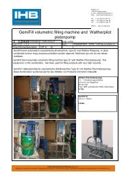
• Sensor codes D, E, F, W, U<br />
Min. clearance<br />
to remove<br />
the cover<br />
Electronic<br />
side<br />
Integral<br />
display<br />
housing<br />
17<br />
(0.67)<br />
Adjustments<br />
26<br />
(1.02)<br />
127 (5.00)<br />
MOUNTING DIMENSIONS<br />
(not for construction unless certified)<br />
Identification tag<br />
36<br />
(1.42)<br />
17<br />
(0.67)<br />
100 (3.94)<br />
Certification<br />
label<br />
Terminal<br />
side<br />
Output meter<br />
housing<br />
Covers locking<br />
screw<br />
L ES<br />
QU<br />
NT<br />
Electrical<br />
connections<br />
86 (3.39)<br />
C I<br />
TA<br />
C I<br />
H<br />
ME'<br />
R CU ITS<br />
W<br />
RC U I<br />
R<br />
T<br />
H<br />
TS<br />
EN FE<br />
TI G<br />
SON<br />
AL<br />
T<br />
CLE BI<br />
GARDER LE COUVER<br />
SO<br />
I VE<br />
VER<br />
CO<br />
U<br />
S<br />
EEP<br />
TEN<br />
K<br />
S<br />
IO N<br />
36<br />
(1.42)<br />
16<br />
(0.63)<br />
61 (2.40)<br />
18<br />
(0.71)<br />
CH 32<br />
135 (5.31)<br />
ø 65 (2.56)<br />
ø 21<br />
(0.83)<br />
CH32<br />
CH 32<br />
1/2" NPT female<br />
connection<br />
DIN-EN837-1<br />
G1/2"B connection<br />
• Sensor code S<br />
Min. clearance<br />
to remove<br />
the cover<br />
17<br />
(0.67)<br />
26<br />
(1.02)<br />
Adjustments<br />
127 (5.00)<br />
Identification tag<br />
36<br />
(1.42)<br />
17<br />
(0.67)<br />
Certification<br />
label<br />
Electrical<br />
connections<br />
86 (3.39)S<br />
Electronic<br />
side<br />
Integral<br />
display<br />
housing<br />
100 (3.94)<br />
Terminal<br />
side<br />
Output meter<br />
housing<br />
Covers locking<br />
screw<br />
L ES<br />
QU<br />
NT<br />
C I<br />
TA<br />
C I<br />
H<br />
ME'<br />
R CU ITS<br />
W<br />
RC U I<br />
R<br />
T<br />
H<br />
TS<br />
EN FE<br />
TI G<br />
SON<br />
AL<br />
T<br />
CLE BI<br />
GARDER LE COUVER<br />
SO<br />
I VE<br />
VER<br />
CO<br />
U<br />
S<br />
EEP<br />
TEN<br />
K<br />
IO N<br />
18<br />
(0.71)<br />
19<br />
(0.75)<br />
33<br />
(1.30)<br />
CH 32<br />
135 (5.31)<br />
ø 65 (2.56)<br />
ø 21<br />
(0.83)<br />
CH27<br />
CH 32<br />
CH32<br />
1/2" NPT female<br />
connection<br />
DIN-EN837-1<br />
G 1/2"B connection<br />
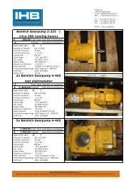
ELECTRICAL CONNECTIONS<br />
+<br />
3 2 8<br />
Internal ground<br />
termination point<br />
-<br />
M+<br />
2<br />
3<br />
4<br />
5<br />
20<br />
40<br />
60<br />
8<br />
Kent-Taylor<br />
80<br />
9<br />
100<br />
10<br />
Remote<br />
indicator<br />
- 1<br />
7<br />
4 5 6<br />
Harting<br />
pin<br />
identification<br />
M<br />
-<br />
+<br />
Line load<br />
250 ohm min<br />
+<br />
+<br />
HART hand-held communicator may be<br />
connected at any wiring termination<br />
point in the loop, providing the<br />
minimum resistance is 250 ohm.<br />
If this is less than 250 ohm, additional<br />
resistance should be added to allow<br />
communications.<br />
-<br />
+<br />
Test points<br />
4-20 mA<br />
External ground<br />
termination point<br />
GND<br />
Hand-held<br />
communicator<br />
1<br />
4<br />
7<br />
2<br />
5<br />
8<br />
0<br />
691HT<br />
F1 F2 F3 F4<br />
3<br />
6<br />
9<br />
+<br />
-<br />
Power<br />
source<br />
-<br />
Optional<br />
ground<br />
-<br />
Receiver<br />
7
ORDERING INFORMATION model <strong>624</strong>EG Gauge Pressure Transmitter<br />
Select one character or set of characters from each category and specify complete catalog number.<br />
Refer to supplementary code and specify another number for each transmitter if additional options are required.<br />
PRODUCT CODE abcde fg h i j k l m n op<br />
BASE MODEL<br />
SENSOR<br />
BOTTOM WORKS<br />
MOUNTING BRACKET<br />
OUTPUT<br />
ELECTRICAL CERTIFICATION<br />
TOP WORKS<br />
ELECTRICAL OPTIONS<br />
0<br />
0<br />
abcde<br />
BASE MODEL - 1st to 5th characters<br />
Gauge pressure transmitter<br />
Code<br />
<strong>624</strong>EG<br />
f<br />
SENSOR<br />
Span limits - 6th character<br />
2.67 and 160 kPa<br />
10 and 600 kPa<br />
40 and 2400 kPa<br />
133 and 8000 kPa<br />
267 and 16000 kPa<br />
2100 and 42000 kPa<br />
26.7 and 1600 mbar<br />
0.1 and 6 bar<br />
0.4 and 24 bar<br />
1.33 and 80 bar<br />
2.67 and 160 bar<br />
21 and 420 bar<br />
10.7 and 642 inH2O<br />
1.45 and 87 psi<br />
5.8 and 348 psi<br />
19.3 and 1160 psi<br />
38.7 and 2320 psi<br />
305 and 6090 psi<br />
D<br />
E<br />
F<br />
W<br />
U<br />
S<br />
g<br />
7th character<br />
Diaphragm material (*)<br />
AISI 316 L ss<br />
Hastelloy C276 ◊ (AISI seat)<br />
Hastelloy C276 ◊<br />
Tantalum<br />
AISI 316 L ss<br />
Hastelloy C276 ◊ (AISI seat)<br />
Hastelloy C276 ◊<br />
Tantalum<br />
AISI 316 L ss<br />
Hastelloy C276 ◊ (AISI seat)<br />
Hastelloy C276 ◊<br />
Note : not available with sensor code S at position "f"<br />
Fill fluid<br />
Silicone oil (**)<br />
Silicone oil (**)<br />
Silicone oil (**)<br />
Silicone oil (**)<br />
Inert fluid<br />
Inert fluid<br />
Inert fluid<br />
Inert fluid<br />
KTFILL-1 (**)<br />
KTFILL-1 (**)<br />
KTFILL-1 (**)<br />
(Note)<br />
(Note)<br />
(Note)<br />
2<br />
6<br />
3<br />
5<br />
A<br />
7<br />
B<br />
D<br />
L<br />
P<br />
N<br />
h<br />
BOTTOM WORKS<br />
Process connection (*) - 8th character<br />
Material<br />
AISI 316 L ss<br />
(Not applicable with tantalum diaphragm code 5 and D at position "g")<br />
Hastelloy C ◊<br />
(Not applicable with AISI 316 L ss diaphragm code 2, A and L at position "g")<br />
Connection<br />
1/2" NPT-f<br />
DIN-EN837-1 - G 1/2"B<br />
1/2" NPT-f<br />
DIN-EN837-1 - G 1/2"B<br />
1<br />
3<br />
A<br />
C<br />
i<br />
j<br />
9th character<br />
Use code<br />
MOUNTING BRACKET - 10th character<br />
Material<br />
None<br />
Carbon steel Not available with AISI 316 L ss housing material code A, C, D, F at position "n"<br />
AISI 316 L ss<br />
0<br />
1<br />
2<br />
3<br />
k<br />
l<br />
11th character<br />
Use code<br />
12. Zeichen<br />
AUSGANG<br />
HART Digitalkommunikation und 4 bis 20 mA<br />
Profibus PA Kommunikation<br />
FOUNDATION Fieldbus Kommunikation<br />
0<br />
G<br />
P<br />
F<br />
Compliance to NACE class II bolting, according to specification MR0175, latest revision<br />
(*) Process wetted-parts<br />
(**) Not available for oxygen service<br />
◊<br />
Hastelloy is a Cabot Corporation trademark<br />
8
ORDERING INFORMATION model <strong>624</strong>EG Gauge Pressure Transmitter<br />
m ELECTRICAL CERTIFICATION - 13th character<br />
General Purpose<br />
ATEX Group II Category 1/2 GD - Flameproof EEx d CESI approval<br />
ATEX Group II Category 1 GD - Intrinsic Safety EEx ia BASEEFA approval<br />
Factory Mutual (FM) and Canadian Standard Association (CSA) approvals (only with 1/2" NPT and M20 electrical connection)<br />
Intrinsic Safety and Flameproof to Standards Australia SAA approval Ex ia IIC T6/75/T4 + Ex d IIC T6/T5<br />
(Note)<br />
Note : not available with output code P and F at position "l"<br />
1<br />
F<br />
L<br />
8<br />
W<br />
TOP WORKS - 14th character<br />
n<br />
Housing material<br />
Aluminium alloy<br />
(Barrel version)<br />
AISI 316 L ss<br />
(Barrel version)<br />
Electrical connection<br />
1/2" NPT<br />
M20 x 1.5 (CM 20)<br />
Pg 13.5<br />
1/2" GK<br />
Harting HAN connector - straight entry<br />
Harting HAN connector - angle entry<br />
1/2" NPT<br />
M20 x 1.5 (CM 20)<br />
Pg 13.5<br />
1/2" GK<br />
(Note)<br />
(Note)<br />
1<br />
2<br />
3<br />
4<br />
5<br />
6<br />
A<br />
C<br />
D<br />
F<br />
Note : requires certification code 1 at position "m"<br />
o<br />
ELECTRICAL OPTIONS - 15th character<br />
Internal meter type<br />
None<br />
Digital LCD output indicator linear 0-100%, user scalable<br />
Digital LCD output indicator linear scale (specify range and engineering units)<br />
Analog output indicator linear 0-100% scale<br />
Analog output indicator, special graduation (to be specified for linear scale)<br />
Digital LCD integral display<br />
Digital LCD integral display and digital LCD output indicator linear 4-20 mA<br />
Digital LCD integral display and analog output indicator linear 0-100% scale<br />
Programmable signal meter and HART configurator (CoMeter)<br />
Programmable signal meter and HART configurator (CoMeter) and digital LCD integral display<br />
(Note)<br />
(Note)<br />
(Note)<br />
(Note)<br />
(Note)<br />
(Note)<br />
(Note)<br />
(Note)<br />
1<br />
3<br />
5<br />
7<br />
9<br />
A<br />
C<br />
E<br />
P<br />
R<br />
Note : not available with output code P and F at position "l"<br />
16th character<br />
p<br />
Electrical options<br />
Standard terminal block<br />
Surge protector (Note)<br />
(Requires certification code, 1, F, 8, W at position "m")<br />
Terminal block for external meter (Note)<br />
Labels language<br />
English<br />
German<br />
Italian<br />
English<br />
German<br />
Italian<br />
English<br />
German<br />
Italian<br />
1<br />
2<br />
7<br />
3<br />
4<br />
8<br />
5<br />
6<br />
9<br />
Note : not available with output code P and F at position "l"<br />
9
ORDERING INFORMATION model <strong>624</strong>EA Absolute Pressure Transmitter<br />
Select one character or set of characters from each category and specify complete catalog number.<br />
Refer to supplementary code and specify another number for each transmitter if additional options are required.<br />
PRODUCT CODE abcde fg h i j k l m n op<br />
BASE MODEL<br />
SENSOR<br />
BOTTOM WORKS<br />
MOUNTING BRACKET<br />
OUTPUT<br />
ELECTRICAL CERTIFICATION<br />
TOP WORKS<br />
ELECTRICAL OPTIONS<br />
0<br />
0<br />
abcde<br />
BASE MODEL - 1st to 5th characters<br />
Absolute pressure transmitter<br />
Code<br />
<strong>624</strong>EA<br />
f<br />
SENSOR<br />
Span limits - 6th character<br />
8 and 160 kPa<br />
30 and 600 kPa<br />
120 and 2400 kPa<br />
400 and 8000 kPa<br />
800 and 16000 kPa<br />
2100 and 42000 kPa<br />
80 and 1600 mbar<br />
0.3 and 6 bar<br />
1.2 and 24 bar<br />
4 and 80 bar<br />
8 and 160 bar<br />
21 and 420 bar<br />
60 and 1200 mmHg<br />
4.35 and 87 psi<br />
17.4 and 348 psi<br />
58 and 1160 psi<br />
116 and 2320 psi<br />
305 and 6090 psi<br />
D<br />
E<br />
F<br />
W<br />
U<br />
S<br />
g<br />
7th character<br />
Diaphragm material (*)<br />
AISI 316 L ss<br />
Hastelloy C276 ◊ (AISI seat)<br />
Hastelloy C276 ◊<br />
AISI 316 L ss<br />
Hastelloy C276 ◊ (AISI seat)<br />
Hastelloy C276 ◊<br />
AISI 316 L ss<br />
Hastelloy C276 ◊ (AISI seat)<br />
Hastelloy C276 ◊<br />
Note : not available with sensor code S at position "f"<br />
Fill fluid<br />
Silicone oil (**)<br />
Silicone oil (**)<br />
Silicone oil (**)<br />
Inert fluid<br />
Inert fluid<br />
Inert fluid<br />
KTFILL-1 (**)<br />
KTFILL-1 (**)<br />
KTFILL-1 (**)<br />
(Note)<br />
(Note)<br />
(Note)<br />
2<br />
6<br />
3<br />
A<br />
7<br />
B<br />
L<br />
P<br />
N<br />
h<br />
BOTTOM WORKS<br />
Process connection (*) - 8th character<br />
Material<br />
AISI 316 L ss<br />
Hastelloy C ◊<br />
(Not applicable with AISI 316 L ss diaphragm code 2, A and L at position "g")<br />
Connection<br />
1/2" NPT-f<br />
DIN-EN837-1 - G 1/2"B<br />
1/2" NPT-f<br />
DIN-EN837-1 - G 1/2"B<br />
1<br />
3<br />
A<br />
C<br />
i<br />
9th character<br />
Use code<br />
0<br />
j<br />
MOUNTING BRACKET - 10th character<br />
Material<br />
None<br />
Carbon steel Not available with AISI 316 L ss housing material code A, C, D, F at position "n"<br />
AISI 316 L ss<br />
1<br />
2<br />
3<br />
k<br />
11th character<br />
Use code<br />
0<br />
l<br />
12th character<br />
OUTPUT<br />
HART digital communication and 4 to 20 mA<br />
Profibus PA communication<br />
FOUNDATION Fieldbus Communication<br />
G<br />
P<br />
F<br />
Compliance to NACE class II bolting, according to specification MR0175, latest revision<br />
(*) Process wetted-parts<br />
(**) Not available for oxygen service<br />
◊<br />
Hastelloy is a Cabot Corporation trademark<br />
10
ORDERING INFORMATION model <strong>624</strong>EA Absolute Pressure Transmitter<br />
m<br />
ELECTRICAL CERTIFICATION - 13th character<br />
General Purpose<br />
ATEX Group II Category 1/2 GD - Flameproof EEx d CESI approval<br />
ATEX Group II Category 1 GD - Intrinsic Safety EEx ia BASEEFA approval<br />
Factory Mutual (FM) and Canadian Standard Association (CSA) approvals (only with 1/2" NPT and M20 electrical connection)<br />
Intrinsic Safety and Flameproof to Standards Australia SAA approval Ex ia IIC T6/T5/T4 + Ex d IIC T6/T5<br />
(Note)<br />
Note : not available with output code P and F at position "l"<br />
1<br />
F<br />
L<br />
8<br />
W<br />
TOP WORKS - 14th character<br />
n<br />
Housing material<br />
Aluminium alloy<br />
(Barrel version)<br />
AISI 316 L ss<br />
(Barrel version)<br />
Electrical connection<br />
1/2" NPT<br />
M20 x 1.5 (CM 20)<br />
Pg 13.5<br />
1/2" GK<br />
Harting HAN connector - straight entry<br />
Harting HAN connector - angle entry<br />
1/2" NPT<br />
M20 x 1.5 (CM 20)<br />
Pg 13.5<br />
1/2" GK<br />
(Note)<br />
(Note)<br />
1<br />
2<br />
3<br />
4<br />
5<br />
6<br />
A<br />
C<br />
D<br />
F<br />
Note : requires certification code 1 at position "m"<br />
o<br />
ELECTRICAL OPTIONS - 15th character<br />
Internal meter type<br />
None<br />
Digital LCD output indicator linear 0-100%, user scalable<br />
Digital LCD output indicator linear scale (specify range and engineering units)<br />
Analog output indicator linear 0-100% scale<br />
Analog output indicator, special graduation (to be specified for linear scale)<br />
Digital LCD integral display<br />
Digital LCD integral display and digital LCD output indicator linear 4-20 mA<br />
Digital LCD integral display and analog output indicator linear 0-100% scale<br />
Programmable signal meter and HART configurator (CoMeter)<br />
Programmable signal meter and HART configurator (CoMeter) and digital LCD integral display<br />
(Note)<br />
(Note)<br />
(Note)<br />
(Note)<br />
(Note)<br />
(Note)<br />
(Note)<br />
(Note)<br />
1<br />
3<br />
5<br />
7<br />
9<br />
A<br />
C<br />
E<br />
P<br />
R<br />
Note : not available with output code P and F at position "l"<br />
16th character<br />
p<br />
Electrical options<br />
Standard terminal block<br />
Surge protector (Note)<br />
(Requires certification code, 1, F, 8, W at position "m")<br />
Terminal block for external meter (Note)<br />
Labels language<br />
English<br />
German<br />
Italian<br />
English<br />
German<br />
Italian<br />
English<br />
German<br />
Italian<br />
1<br />
2<br />
7<br />
3<br />
4<br />
8<br />
5<br />
6<br />
9<br />
Note : not available with output code P and F at position "l"<br />
11
ORDERING INFORMATION<br />
Select one character or set of characters from each category and specify complete catalog number in addition to each<br />
transmitter code, if required.<br />
PRODUCT CODE ab c d e f<br />
BASE MODEL<br />
CONFIGURATION<br />
CALIBRATION<br />
PROCEDURE<br />
INTEGRAL MOUNTING OF ASSOCIATED INSTRUMENTATION<br />
ab<br />
BASE MODEL - 1st to 2nd characters<br />
Supplementary code<br />
Code<br />
SC<br />
c<br />
CONFIGURATION - 3rd character<br />
Standard - Pressure = kPa; Temperature = deg. C<br />
Standard - Pressure = inH2O/psi (@ 20°C); Temperature = deg. F<br />
Standard - Pressure = inH2O/psi (@ 4°C); Temperature = deg. F<br />
Standard - Pressure = inH2O/psi (@ 20°C); Temperature = deg. C<br />
Standard - Pressure = inH2O/psi (@ 4°C); Temperature =- deg. C<br />
Custom<br />
1<br />
2<br />
3<br />
4<br />
5<br />
C<br />
d<br />
CALIBRATION - 4th character<br />
Calibration range<br />
Standard (max span = 0 to URL)<br />
At specified range<br />
Calibration<br />
Reference temperature<br />
Operating temperature<br />
Reference temperature<br />
Operating temperature<br />
Certificate<br />
None<br />
Yes (3 copies)<br />
None<br />
Yes (3 copies)<br />
None<br />
Yes (3 copies)<br />
None<br />
Yes (3 copies)<br />
1<br />
2<br />
3<br />
4<br />
5<br />
6<br />
7<br />
8<br />
e<br />
5th character<br />
PROCEDURE<br />
None<br />
Oxygen service cleaning (Note 1)<br />
Note 1 : not applicable to transmitter model <strong>624</strong>EG/EA (sensor code S)<br />
Material traceability<br />
None<br />
To EN10204 - 3.1.B (certificates for flanges, adapters, diaphragms)<br />
To EN10204 - 2.1 (declaration for instrument)<br />
None<br />
To EN10204 - 3.1.B (certificates for flanges, adapters, diaphragms)<br />
To EN10204 - 2.1 (declaration for instrument)<br />
0<br />
A<br />
B<br />
2<br />
C<br />
F<br />
f<br />
INTEGRAL MOUNTING OF ASSOCIATED INSTRUMENTATION - 6th character<br />
None<br />
For valve manifold<br />
0<br />
1<br />
The Company's policy is one of continuous product<br />
improvement and the right is reserved to modify the<br />
specifications contained herein without notice.<br />
SS/<strong>624</strong>EG/A Rev. 5<br />
<strong>ABB</strong> Instrumentation spa<br />
Via Statale 113<br />
22016 Lenno (Como)<br />
Italia<br />
Tel. 0344 58111<br />
Facsimile 0344 56278<br />
12<br />
<strong>ABB</strong> Automation Ltd.<br />
Howard Road<br />
St. Neots, Cambs.<br />
England PE19 3EU<br />
Tel. (01480) 475321,<br />
Facsimile (01480) 217948<br />
<strong>ABB</strong> Automation Inc.<br />
125 East County Line Road<br />
Warminster, Pa.<br />
18974-4995 USA<br />
Tel. (215) 674-6693/6320/6777<br />
Facsimile (215) 674-7184