stress analysis of composite material embedded with optical fiber ...
stress analysis of composite material embedded with optical fiber ...
stress analysis of composite material embedded with optical fiber ...

Create successful ePaper yourself
Turn your PDF publications into a flip-book with our unique Google optimized e-Paper software.
Asia-Pacific Conference on FRP in Structures (APFIS 2007)<br />
S.T. Smith (ed)<br />
© 2007 International Institute for FRP in Construction<br />
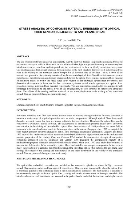
STRESS ANALYSIS OF COMPOSITE MATERIAL EMBEDDED WITH OPTICAL<br />
FIBER SENSOR SUBJECTED TO ANTI-PLANE SHEAR<br />
S.C. Her * and B.R. Yao<br />
Department <strong>of</strong> Mechanical Engineering, Yuan Ze University, Taiwan.<br />
Email: mesch@saturn.yzu.edu.tw<br />
ABSTRACT<br />
The use <strong>of</strong> smart <strong>material</strong>s has grown considerably over the past two decades in applications ranging from civil<br />
structure to aerospace vehicle. Fiber optic sensor <strong>with</strong> small size, light weight and immunity to electromagnetic<br />
interference can be <strong>embedded</strong> and integrated into the host <strong>material</strong> to form an ideally smart structure system.<br />
One must recognize that <strong>optical</strong> <strong>fiber</strong>s are foreign entities to the host structure, therefore will induce high <strong>stress</strong><br />
state in the vicinity <strong>of</strong> the <strong>embedded</strong> sensor irrespective <strong>of</strong> the small size <strong>of</strong> the <strong>fiber</strong>. This is a result <strong>of</strong> the<br />
<strong>material</strong> and geometric discontinuity introduced by the <strong>embedded</strong> <strong>optical</strong> <strong>fiber</strong>. To address this concern, present<br />
paper focuses the attention on constitutent interaction between the <strong>optical</strong> <strong>fiber</strong>, coating, matrix and host <strong>material</strong>.<br />
An analytical model to predict the <strong>stress</strong> fields in the vicinity <strong>of</strong> the <strong>embedded</strong> <strong>optical</strong> <strong>fiber</strong> are derived. The<br />
theoretical development is based on the four concentric cylinders model which represents the <strong>optical</strong> <strong>fiber</strong>,<br />
protective coating, matrix and host <strong>material</strong>, respectively. The host <strong>material</strong> is considered to be a <strong>composite</strong> <strong>with</strong><br />
reinforced <strong>fiber</strong> parallel to the <strong>optical</strong> <strong>fiber</strong>. In this investigation, the host structure is subjected to anti-plane<br />
shear. The effects <strong>of</strong> the coating and host <strong>material</strong> on the <strong>stress</strong> distribution in the vicinity <strong>of</strong> the <strong>embedded</strong><br />
<strong>optical</strong> <strong>fiber</strong> are presented through a parametric study.<br />
KEYWORDS<br />
Embedded <strong>optical</strong> <strong>fiber</strong>, smart structure, concentric cylinder, in-plane shear, anti-plane shear.<br />
INTRODUCTION<br />
Structures <strong>embedded</strong> <strong>with</strong> <strong>fiber</strong> optic sensor are considered as primary sensing candidates for smart structures to<br />
monitor a wide range <strong>of</strong> physical quantities such as strain, temperature. Although <strong>optical</strong> <strong>fiber</strong>s have small<br />
diameter, we must realize that they are foreign entities to the host structure. Therefore, the <strong>optical</strong> <strong>fiber</strong> can be<br />
considered as cylindrical elastic inclusion. The discontinuity <strong>of</strong> <strong>material</strong> and geometry induce <strong>stress</strong> and strain<br />
concentration in the vicinity <strong>of</strong> the <strong>embedded</strong> <strong>optical</strong> <strong>fiber</strong>. Benventiste et al. 1989 predicted the <strong>stress</strong> field in<br />
<strong>composite</strong> <strong>with</strong> coated inclusion based on the average <strong>stress</strong> in the matrix. Dasgupta et al. 1992 investigated the<br />
resin pocket geometry for <strong>stress</strong> <strong>analysis</strong> <strong>of</strong> <strong>optical</strong> <strong>fiber</strong> <strong>embedded</strong> in laminates <strong>composite</strong>s. Dasgupta and Sirkis<br />
1992 showed that strain concentrations near an <strong>embedded</strong> <strong>optical</strong> <strong>fiber</strong> are highly dependent on the thickness and<br />
<strong>material</strong> properties <strong>of</strong> the coating. Case and Carman 1994 studied the compression strength <strong>of</strong> <strong>composite</strong>s<br />
containing <strong>embedded</strong> sensors. Eskandari and Carman 1996 predicted the compression strength <strong>of</strong> a<br />
unidirectional polymer <strong>composite</strong> <strong>embedded</strong> <strong>with</strong> circular <strong>fiber</strong>s. Melin et al. 1997 used moiré inerferometry to<br />
measure the deformation fields around the <strong>optical</strong> <strong>fiber</strong>s <strong>embedded</strong> in carbon/epoxy <strong>composite</strong>s. In the present<br />
study, the objective is to calculate the <strong>stress</strong> field around the <strong>embedded</strong> <strong>optical</strong> <strong>fiber</strong> subjected to anti-plane shear<br />
loading. The effects <strong>of</strong> the coating and host <strong>material</strong> on the <strong>stress</strong> distribution in the vicinity <strong>of</strong> the <strong>embedded</strong><br />
<strong>optical</strong> <strong>fiber</strong> are presented through a parametric study.<br />
ANTI-PLANE SHEAR ANALYTICAL MODEL<br />
The <strong>optical</strong> <strong>fiber</strong> <strong>embedded</strong> <strong>composite</strong>s are modeled as four concentric cylinders as shown in Fig.1, represent<br />
<strong>optical</strong> <strong>fiber</strong>, coating, matrix and host <strong>material</strong>, respectively. This geometry is applicable when the <strong>optical</strong> <strong>fiber</strong><br />
is <strong>embedded</strong> parallel to the reinforcing <strong>fiber</strong>s in the surrounding host <strong>composite</strong>. The host <strong>material</strong> is assumed to<br />
be transversely isotropic, while the <strong>optical</strong> <strong>fiber</strong>, coating and matrix are considered as isotropic <strong>material</strong>s. The<br />
interfaces between each constituent are assumed to be perfect bonds, such that the tractions and displacements<br />
593
are continuous across the each interface. Fig.2 shows <strong>optical</strong> <strong>fiber</strong> <strong>embedded</strong> <strong>composite</strong> subjected to anti-plane<br />
shear <strong>stress</strong>σ xz<br />
= τ<br />
0<br />
in the far field.<br />
Figure 1. Four concentric cylinders model<br />
Figure 2. Anti-plane shear loading<br />
The equilibrium equations for the anti-plane problem can be expressed in terms <strong>of</strong> displacements as follows<br />
1<br />
u<br />
r u 1<br />
z, rr+ z, r+ 2<br />
uz,<br />
θθ<br />
= 0<br />
r<br />
(1)<br />
Solutions for the partial differential equations are<br />
n An<br />
uz ( r,<br />
θ,<br />
z)<br />
= [ + Bnr]cosθ<br />
r<br />
n = f , i , m ,c<br />
(2)<br />
Where the superscript and subscript n = f , i , m, c refer to <strong>optical</strong> <strong>fiber</strong>, coating, matrix and <strong>composite</strong>,<br />
respectively, throughout the paper. A n<br />
, B<br />
n<br />
are unknown constants associated <strong>with</strong> each <strong>material</strong>, can be<br />
determined by the far field and interface continuity conditions. To avoid the displacement singularity at r = 0 ,<br />
let the constant A = 0 . The shear <strong>stress</strong>es in each <strong>material</strong> can be written as<br />
f<br />
A<br />
σ<br />
rz<br />
= C<br />
n n<br />
55<br />
[ − + B<br />
n<br />
]cosθ<br />
2<br />
r<br />
(3)<br />
A<br />
σ<br />
θz<br />
= C<br />
55<br />
[ − −B<br />
n<br />
]sinθ<br />
2<br />
r<br />
n<br />
where C 55<br />
represents the constant <strong>of</strong> stiffness matrix (σ<br />
ij<br />
= C<br />
ijε<br />
j<br />
)associate <strong>with</strong> each <strong>material</strong>, in the case<br />
n<br />
<strong>of</strong> isotropic <strong>material</strong>, C 55<br />
equals to the shear modulus.<br />
The far field conditions<br />
σ<br />
xz<br />
= τ 0<br />
σ<br />
yz<br />
= 0 r → ∞<br />
can be rewritten in polar coordinate system as follow<br />
σ<br />
rz<br />
= σ<br />
yz<br />
sinθ<br />
+ σ<br />
xz<br />
cosθ<br />
= τ<br />
0<br />
cosθ<br />
(4a)<br />
σ θ z<br />
= σ<br />
yz<br />
cosθ<br />
−σ<br />
xz<br />
sinθ<br />
= −τ<br />
0<br />
sinθ<br />
(4b)<br />
Substituting eq(3) into eq(4) yields<br />
C c 55Bc<br />
= τ 0<br />
(5)<br />
The interface continuity conditions can be expressed as<br />
c<br />
m<br />
c<br />
m<br />
u<br />
z<br />
( rm<br />
) = u<br />
z<br />
( rm<br />
) ; σ<br />
rz<br />
( rm<br />
) = σ<br />
rz<br />
( rm<br />
)<br />
m<br />
i<br />
m<br />
i<br />
u<br />
z<br />
( ri<br />
) = u<br />
z<br />
( ri<br />
) ; σ<br />
rz<br />
( ri<br />
) = σ<br />
rz<br />
( ri<br />
)<br />
(6)<br />
i<br />
u<br />
f<br />
r ) = u ( r ) ;<br />
i<br />
σ<br />
f<br />
r ) = σ ( r )<br />
z<br />
(<br />
f z f<br />
rz<br />
(<br />
i rz f<br />
Where r<br />
m<br />
, r<br />
i<br />
, rf<br />
are the radii <strong>of</strong> matrix, coating and optic <strong>fiber</strong>, respectively.<br />
Substituting eq(2) and eq(3) into eq(6), results<br />
Am<br />
Ac<br />
+ B<br />
m<br />
− − B<br />
c<br />
= 0<br />
(7a)<br />
2 2<br />
rm<br />
rm<br />
A i<br />
Am<br />
+ B − − = 0<br />
2 i<br />
B<br />
(7b)<br />
2 m<br />
r r<br />
i<br />
i<br />
APFIS 2007 594
The constants<br />
n<br />
Ai<br />
B<br />
f<br />
− − B<br />
i<br />
= 0 (7c)<br />
2<br />
r<br />
f<br />
− C<br />
A + C B + C A m m m<br />
c c c<br />
55 m<br />
− C B =<br />
2 55 55 2 55 c<br />
0 (7d)<br />
r<br />
r<br />
m<br />
m<br />
− C<br />
A A<br />
i i i<br />
m m m<br />
55<br />
+ C B<br />
i<br />
+ C − C B =<br />
2 55 55 2 55 m<br />
0 (7e)<br />
r<br />
r<br />
i<br />
i<br />
C B C A f<br />
i i i<br />
55 f<br />
+<br />
55 2<br />
− C<br />
55Bi<br />
= 0<br />
(7f)<br />
r<br />
f<br />
A , B can be obtained by solving the system equations (5) and (7). Back substituting these<br />
n<br />
constants into eq(2) and eq(3), yields to the displacements and <strong>stress</strong>es.<br />
NUMERICAL EXAMPLES<br />
The <strong>material</strong> properties using in the numerical examples for the <strong>optical</strong> <strong>fiber</strong> are E<br />
f<br />
= 431 GPa , ν<br />
f<br />
= 0.25 ; for<br />
matrix are E m<br />
= 2. 89GPa<br />
, ν<br />
m<br />
= 0. 35 . The <strong>material</strong> properties <strong>of</strong> coating and <strong>composite</strong> (host structure) are<br />
varying to investigate the influence <strong>of</strong> coating and host structure on the <strong>stress</strong> distribution in the vicinity <strong>of</strong><br />
<strong>embedded</strong> <strong>optical</strong> <strong>fiber</strong>. The ratios <strong>of</strong> radii between <strong>optical</strong> <strong>fiber</strong>, coating and matrix are<br />
r<br />
f<br />
: ri<br />
: rm<br />
= 0.768 : 0.847 :1. The radius <strong>of</strong> the <strong>composite</strong> is assumed to be infinite i.e. r<br />
c<br />
→ ∞ . The <strong>optical</strong><br />
<strong>fiber</strong> <strong>embedded</strong> <strong>composite</strong>s is subjected to far field anti-plane shear σ<br />
xz<br />
= τ<br />
0<br />
. The shear <strong>stress</strong>es <strong>of</strong> σ<br />
rz<br />
and<br />
0 0 0<br />
σ<br />
θz<br />
along the radial direction for θ = 0 , 45 , 90 are calculated.<br />
To investigate the effect <strong>of</strong> coating and host <strong>material</strong> on the <strong>stress</strong> distribution, two different coatings named<br />
polymide and acrylate, three different host <strong>material</strong>s named graphite/epoxy, gelion/epoxy and T300/epoxy are<br />
considered as shown in table 1. Thus, total <strong>of</strong> six different combinations <strong>of</strong> host <strong>material</strong> and coating are<br />
obtained as shown in table 2. The <strong>stress</strong> distributions for these six different combinations are shown in Figs.3 - 8,<br />
0<br />
respectively. The numerical results show that the shear <strong>stress</strong> σ<br />
rz<br />
is decreasing as angle θ increasing from 0<br />
0<br />
0<br />
0<br />
to 90 , the shear <strong>stress</strong> σ<br />
θz<br />
is increasing as angle θ increasing from 0 to 90 . Both the maximum shear<br />
<strong>stress</strong>es σ<br />
rz<br />
and σ<br />
θz<br />
are occurred in the <strong>optical</strong> <strong>fiber</strong>. The shear <strong>stress</strong>es are also increased <strong>with</strong> the increase <strong>of</strong><br />
shear modulus <strong>of</strong> coating. The shear <strong>stress</strong>es exhibit the opposite trend as varying the host <strong>material</strong>, i.e.<br />
decreased <strong>with</strong> the increase <strong>of</strong> shear modulus <strong>of</strong> host <strong>material</strong>.<br />
Table 1. Material properties <strong>of</strong> coating and <strong>composite</strong><br />
polyimide E = 3 .1GPa<br />
ν = 0. 32<br />
coating<br />
acrylate E = 5 .5 GPa ν = 0. 35<br />
<strong>composite</strong><br />
Graphite/epoxy<br />
Gelion70/Epoxy<br />
T300/epoxy<br />
E L<br />
= 149GPa<br />
E T<br />
= 11. 4GPa<br />
G LT<br />
= 4. 5GPa<br />
G TT<br />
= 4. 385GPa ν = 0. 3<br />
LT<br />
E L<br />
= 298. 8GPa<br />
E T<br />
= 4. 3GPa<br />
G LT<br />
= 3. 5GPa<br />
G TT<br />
= 1. 6285GPa ν = 0. 32<br />
LT<br />
E L<br />
= 52. 4GPa<br />
E T<br />
= 50. 6GPa<br />
G LT<br />
= 3. 5GPa<br />
G TT<br />
= 19. 5GPa ν = 0. 06<br />
LT<br />
APFIS 2007 595
Table 2. Six different <strong>material</strong> combinations<br />
combination Coating <strong>composite</strong><br />
1 Polyimide Graphite/epoxy<br />
2 Polyimide Gelion/epoxy<br />
3 Polyimide T300/epoxy<br />
4 Acrylate Graphite/epoxy<br />
5 Acrylate Gelion/epoxy<br />
6 Acrylate T300/epoxy<br />
Figure 3. Stress variation <strong>with</strong> radius<br />
Figure4. Stress variation <strong>with</strong> radius<br />
for <strong>material</strong> combination 1 for <strong>material</strong> combination 2<br />
Figure 5. Stress variation <strong>with</strong> radius<br />
Figure 6. Stress variation <strong>with</strong> radius<br />
for <strong>material</strong> combination 3 for <strong>material</strong> combination 4<br />
Figure 7. Stress variation <strong>with</strong> radius<br />
Figure 8. Stress variation <strong>with</strong> radius<br />
for <strong>material</strong> combination 5 for <strong>material</strong> combination 6<br />
APFIS 2007 596
CONCLUSIONS<br />
In this study, the <strong>stress</strong> distribution <strong>of</strong> <strong>optical</strong> <strong>fiber</strong> <strong>embedded</strong> <strong>composite</strong> subjected to anti-plane shear loadings is<br />
investigated basing on the four concentric cylinders model. The influence <strong>of</strong> the host <strong>material</strong> and coating on the<br />
<strong>stress</strong> concentration is presented through numerical examples.<br />
.<br />
ACKNOWLEDGMENTS<br />
The authors gratefully acknowledge the financial support provided by National Science Council <strong>of</strong> R.O.C. under<br />
grant no. NSC-93-2212-E-155-007 for this work.<br />
REFERENCES<br />
Benveniste, Y., Dvorak, G.J. and Chen, T. (1989). “Stress fields in <strong>composite</strong> <strong>with</strong> coated inclusions”,<br />
Mechanics <strong>of</strong> Materials, 7, 305-307.<br />
Case, S.W. and Carman, G.P. (1994). “Compression strength <strong>of</strong> <strong>composite</strong>s containing <strong>embedded</strong> sensors or<br />
actuator”, J. <strong>of</strong> Intelligent Material Systems and Structures, 5, 4-11.<br />
Dasgupta ,A. and Sirkis, J.S. (1992). “Importance <strong>of</strong> coating to <strong>optical</strong> <strong>fiber</strong> sensors <strong>embedded</strong> in smart<br />
structures”, AIAA, 30, 1337-1343.<br />
Dasgupta, A., Wan, Y. and Sirkis, J.S. (1992). “Prediction <strong>of</strong> resin pocket geometry for <strong>stress</strong> <strong>analysis</strong> <strong>of</strong> <strong>optical</strong><br />
<strong>fiber</strong>s <strong>embedded</strong> in laminated <strong>composite</strong>s”, Smart Mater. Struct., 1, 101-107.<br />
Eskandari, S. and Carman, G. (1996). “Evaluating the influence <strong>of</strong> <strong>fiber</strong> coating on the compression strength <strong>of</strong> a<br />
unidirectional polymer <strong>composite</strong>”, J. <strong>of</strong> Composite Material, 30, 1958-1976.<br />
Melin, L.G., Levin K., Nilsson, S., Palmer, S.J. and Rae, P. (1999). “A study <strong>of</strong> the displacement field around<br />
<strong>embedded</strong> fibre optic sensors”, Composites: Part A, 30, 1267-1275.<br />
APFIS 2007 597
APFIS 2007 598