Navier-Stokes Analysis of Helicopter Rotor Aerodynamics in Hover ...
Navier-Stokes Analysis of Helicopter Rotor Aerodynamics in Hover ...
Navier-Stokes Analysis of Helicopter Rotor Aerodynamics in Hover ...

You also want an ePaper? Increase the reach of your titles
YUMPU automatically turns print PDFs into web optimized ePapers that Google loves.
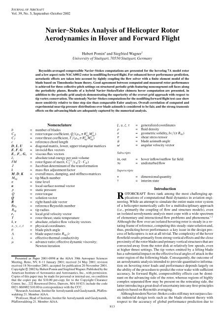
JOURNAL OF AIRCRAFT<br />
Vol. 39, No. 5, September–October 2002<br />
<strong>Navier</strong>–<strong>Stokes</strong> <strong>Analysis</strong> <strong>of</strong> <strong>Helicopter</strong> <strong>Rotor</strong><br />
<strong>Aerodynamics</strong> <strong>in</strong> <strong>Hover</strong> and Forward Flight<br />
Hubert Pom<strong>in</strong> ¤ and Siegfried Wagner †<br />
University <strong>of</strong> Stuttgart, 70550 Stuttgart, Germany<br />
Reynolds-averaged compressible <strong>Navier</strong>–<strong>Stokes</strong> computations are presented for the hover<strong>in</strong>g 7A model rotor<br />
and a low aspect ratio NACA0012 rotor <strong>in</strong> nonlift<strong>in</strong>g forward � ight. For enhanced hover performance prediction,<br />
aeroelastic effects are taken <strong>in</strong>to account by tightly coupl<strong>in</strong>g the � ow solver with a � nite element model <strong>of</strong> the<br />
blade based on Timoshenko beam theory. Good agreement between computed and measured rotor performance<br />
is achieved for three collective pitch sett<strong>in</strong>gs on structured periodic grids featur<strong>in</strong>g noncongruent cell faces along<br />
the periodicity planes. Results <strong>of</strong> a hybrid <strong>Navier</strong>–<strong>Stokes</strong>/Euler chimera hover computation are presented, <strong>in</strong><br />
addition to the periodic grid analysis demonstrat<strong>in</strong>g the superiority <strong>of</strong> the overset grid approach with respect to<br />
tip vortex conservation. The unsteady <strong>Navier</strong>–<strong>Stokes</strong> computations for the nonlift<strong>in</strong>g forward � ight test case show<br />
more sensitivity relative to time step size than comparable Euler analyses. Overall correlation <strong>of</strong> computed and<br />
experimental near-tip pressure distributions over blade azimuth is considered to be fair, and the strong transonic<br />
effects on the advanc<strong>in</strong>g blade are adequately captured by the numerical analysis.<br />
Nomenclature<br />
b = number <strong>of</strong> blades<br />
C Q = rotor torque coef� cient, Q=.½1¼ R 3<br />
tip<br />
M 2<br />
tip /<br />
CT = rotor thrust coef� cient, T=.½1¼ R 2 tip M 2 tip /<br />
c = reference chord length<br />
D; L; U = diagonal matrix, lower, upper triangular matrices<br />
E; F; G = <strong>in</strong>viscid � ux vectors<br />
Ev; Fv; Gv = viscous � ux vectors<br />
Ne t = absolute total energy per unit volume<br />
FM = rotor � gure <strong>of</strong> merit, C 3=2<br />
T =.p 2 ¢ C Q/<br />
J = Jacobian determ<strong>in</strong>ant <strong>of</strong> the transformation<br />
k = mass � ux adjustment factor<br />
M; D; K = overall mass, damp<strong>in</strong>g, and stiffness matrices<br />
M tip = tip Mach number<br />
n = time level<br />
n = local surface normal vector<br />
p = static pressure<br />
Q = rotor torque<br />
Q = solution vector<br />
R = right-hand side vector<br />
Re 0 = reference Reynolds number<br />
R tip = tip radius<br />
r¿ = local grid velocity vector<br />
T = rotor thrust; static temperature<br />
Nv; v = absolute, relative � ow velocity vectors<br />
x; y; z; t = physical coord<strong>in</strong>ates<br />
µ = blade pitch angle<br />
3 = blade aspect ratio R tip=c<br />
¸ = effective thermal conductivity<br />
¹ = advance ratio; effective dynamic viscosity;<br />
Newton iteration<br />
Presented as Paper 2001-0998 at the AIAA 39th Aerospace Sciences<br />
Meet<strong>in</strong>g, Reno, NV, 8–11 January 2001; received 24 May 2001; revision<br />
received 18 November 2001; accepted for publication 20 November 2001.<br />
Copyright c° 2002 by Hubert Pom<strong>in</strong> and Siegfried Wagner. Published by the<br />
American Institute <strong>of</strong> Aeronautics and Astronautics, Inc., with permission.<br />
Copies <strong>of</strong> this paper may be made for personal or <strong>in</strong>ternal use, on condition<br />
that the copier pay the $10.00 per-copy fee to the Copyright Clearance<br />
Center, Inc., 222 Rosewood Drive, Danvers, MA 01923; <strong>in</strong>clude the code<br />
0021-8669/02 $10.00 <strong>in</strong> correspondence with the CCC.<br />
¤ Research Assistant, Institut für Aerodynamik und Gasdynamik, Pfaffenwaldr<strong>in</strong>g<br />
21. Member AIAA.<br />
† Pr<strong>of</strong>essor, Head <strong>of</strong> Institute, Institut für Aerodynamik und Gasdynamik,<br />
Pfaffenwaldr<strong>in</strong>g 21. Member AIAA.<br />
813<br />
�; ´; �; ¿ = generalized coord<strong>in</strong>ates<br />
½ = � uid density<br />
¾ = geometric solidity, bc=.¼ Rtip/<br />
¿ = shear stress tensor<br />
à = blade azimuth angle<br />
! = angular velocity vector<br />
Subscripts<br />
<strong>in</strong>, out = hover <strong>in</strong>� ow/out� ow far � eld<br />
1 = undisturbed � ow<br />
Superscripts<br />
¤ = dimensional quantity<br />
† = <strong>in</strong>terim state<br />
Introduction<br />
ROTORCRAFT � ows rank among the most challeng<strong>in</strong>g applications<br />
<strong>of</strong> computational � uid dynamics <strong>in</strong> aviation eng<strong>in</strong>eer<strong>in</strong>g.<br />
While an attempt to simulate the entire ma<strong>in</strong> rotor system<br />
<strong>of</strong> a helicopter numerically calls for a multidiscipl<strong>in</strong>ary approach<br />
(i.e., primarily the coupl<strong>in</strong>g <strong>of</strong> � ow and structure models), even<br />
an isolated aerodynamic analysis must cope with a wide spectrum<br />
<strong>of</strong> elementary and <strong>in</strong>teractional � ow problems and phenomena. 1;2<br />
Although the � ow over an isolated hover<strong>in</strong>g rotor is steady <strong>in</strong> a rotat<strong>in</strong>g<br />
frame <strong>of</strong> reference, comput<strong>in</strong>g this steady-state solution and,<br />
thus, predict<strong>in</strong>g hover performance- a key issue <strong>in</strong> the design process<br />
<strong>of</strong> helicopters-is not at all trivial. The complexity <strong>of</strong> the hover<br />
� ow� eld results primarily from strong vortical effects and the close<br />
proximity <strong>of</strong> the rotor blades and primary vorticalstructuresthat are<br />
convected away from the rotor disk at relatively low speeds, even<br />
at higher thrust sett<strong>in</strong>gs. The tip vortex emitted by a lift<strong>in</strong>g blade<br />
has a substantialimpact on the effectivelocal angles <strong>of</strong> attack <strong>in</strong> the<br />
outer region <strong>of</strong> the follow<strong>in</strong>g blade. Consequently, the outcome <strong>of</strong><br />
an aerodynamic analysis <strong>in</strong>tended to provide quantitative <strong>in</strong>formation<br />
on hover<strong>in</strong>g rotor loads and performance depends largely on<br />
the ability <strong>of</strong> the procedure to predict the rotor wake with suf� cient<br />
accuracy. In forward � ight, compressibility effects can be dom<strong>in</strong>ant<br />
on the advanc<strong>in</strong>g side <strong>of</strong> the rotor, whereas regions <strong>of</strong> highly<br />
complex separated � ow may be present on the retreat<strong>in</strong>g side, the<br />
latter <strong>in</strong>troduc<strong>in</strong>ga great deal <strong>of</strong> uncerta<strong>in</strong>ty<strong>in</strong>to any � rst-pr<strong>in</strong>ciples<br />
analysis based on Reynolds averag<strong>in</strong>g.<br />
Althoughmodern <strong>Navier</strong>–<strong>Stokes</strong> codes stillmay not surpassclassic<br />
<strong>in</strong>dustrial design tools such as the blade element theory with<br />
respect to the accuracy <strong>of</strong> global performance prediction due to
814 POMIN AND WAGNER<br />
limitations <strong>in</strong> comput<strong>in</strong>g resources, the yet unanswered question <strong>of</strong><br />
grid-<strong>in</strong>dependentsolutions, 3;4 and numerical diffusion <strong>of</strong> the rotor<br />
wake, they can, <strong>in</strong> contrast to more elementaryapproaches,provide<br />
valuable local <strong>in</strong>sight <strong>in</strong>to the three-dimensional� ow� eld and <strong>in</strong>teractional<br />
phenomena. Over the past decade, numerous authors have<br />
presentedEuler and <strong>Navier</strong>–<strong>Stokes</strong> codes for helicopterrotor applications,<br />
for example, Krämer, 5 Boniface and Sidès, 6 Sr<strong>in</strong>ivasan and<br />
Baeder, 7 Stangl, 8 Wake and Baeder, 9 Wehr, 10 Pahlke, 11 Hariharan<br />
and Sankar, 12 Strawn and Ahmad, 4 and Beaumier et al. 13 In the<br />
aforementioned references, however, either rigid blade behavior is<br />
assumed or, for hover computations,known blade deformations obta<strong>in</strong>ed<br />
from experiment or more elementary analysis tools are fed<br />
<strong>in</strong>to the � ow solver by a priori grid deformation. Incorporat<strong>in</strong>g the<br />
<strong>in</strong>terdependence <strong>of</strong> blade dynamics and � ow� eld <strong>in</strong>to the analysis<br />
will signi� cantly enhance its predictive capabilities for all helicopter<br />
� ight scenarios at a negligible <strong>in</strong>crease <strong>in</strong> comput<strong>in</strong>g cost<br />
and at least opens up the door toward the numerical simulation <strong>of</strong>,<br />
for example, adaptive rotor structures, vibration control, and aeroacoustics.<br />
The partitioned procedures approach 14;15 ma<strong>in</strong>ta<strong>in</strong>s � ow<br />
and structure solvers as entirely separate programs that exchange<br />
<strong>in</strong>formation along their common physical boundary, the rotor blade<br />
surface,throughoutthe computation.Such a modular procedurewas<br />
developed by Hierholz 16 and Buchtala 17 based on the Euler � ow<br />
model.<br />
In this paper, aeroelastic hover computations on periodic structured<br />
grids are presented us<strong>in</strong>g the INROT <strong>Navier</strong>–<strong>Stokes</strong> � ow<br />
solver 18 <strong>in</strong> conjunctionwith the � niteelementcodeDYNROT. 17 Viscous<br />
aeroelasticsimulations<strong>of</strong> adaptive helicopterrotors <strong>in</strong> forward<br />
� ight be<strong>in</strong>g the long term goal, � rst results <strong>of</strong> hybrid calculations<br />
on overset grids (chimera) and a study compar<strong>in</strong>g unsteady Euler<br />
and <strong>Navier</strong>–<strong>Stokes</strong> results for a nonlift<strong>in</strong>g forward � ight scenario,<br />
are presented.<br />
Govern<strong>in</strong>g Equations<br />
Flow Model<br />
Formulated<strong>in</strong> a steadilyrotat<strong>in</strong>g Cartesian system, the Reynoldsaveraged<br />
<strong>Navier</strong>–<strong>Stokes</strong> (RANS) equationsfor unsteady compressible<br />
three-dimensional� ows are given by<br />
@½<br />
C r.½v/ D 0 (1)<br />
@t<br />
@.½ Nv/<br />
@t C [r.½v �Nv/]T D ¡r p C 1<br />
[r¿ ]<br />
Re0 T ¡ ½ ! £ Nv (2)<br />
@ Net<br />
@t C r.Netv/ D ¡r. pNv/ C 1<br />
r.¿ Nv ¡ q/ (3)<br />
Re0 where Nv and v are the � ow velocitiesrelativeto the <strong>in</strong>ertialandthe rotat<strong>in</strong>g<br />
system, respectively.Newtonian � uid properties are assumed<br />
and Sutherland’s law (see Ref. 19), as well as <strong>Stokes</strong>’ hypothesis<br />
(see Ref. 19) are employed to calculate the molecular dynamic viscosity<br />
and the components <strong>of</strong> the shear stress tensor. To close the<br />
preced<strong>in</strong>g system <strong>of</strong> partial differential equations, thermally and<br />
calorically perfect gas is assumed. Furthermore, the eddy viscosity<br />
¹t is <strong>in</strong>troducedas the output <strong>of</strong> an appropriateturbulencemodel to<br />
compute the effectivedynamic viscosity¹ and the effectivethermal<br />
conductivity¸ needed for the calculation<strong>of</strong> the heat � ux vector. All<br />
RANS analyses presented <strong>in</strong> this paper are carried out us<strong>in</strong>g the<br />
algebraic two-layer model accord<strong>in</strong>g to Baldw<strong>in</strong> and Lomax 20 because<br />
<strong>of</strong> its robustness and low comput<strong>in</strong>g cost. The <strong>Navier</strong>–<strong>Stokes</strong><br />
equations are rewritten <strong>in</strong> computational space<br />
@Q<br />
@¿<br />
C @E<br />
@�<br />
�<br />
@F @G 1 @Ev<br />
C C ¡<br />
@´ @� Re0 @�<br />
C @Fv<br />
@´<br />
´<br />
@Gv<br />
C<br />
@�<br />
D R (4)<br />
us<strong>in</strong>g the time-dependent transformation �; ´; � : D f .x; y; z; t/,<br />
¿ D t to permit aeroelasticrotor analyses on deformable body-� tted<br />
structured grids undergo<strong>in</strong>garbitrary motion relative to the rotat<strong>in</strong>g<br />
frame <strong>of</strong> reference. The <strong>in</strong>viscid � uxes E, F, and G are given <strong>in</strong><br />
arbitrary Lagrangian–Eulerian form to take <strong>in</strong>to account the local<br />
grid velocity r¿ D .x ¿ ; y ¿ ; z ¿/ T relative to the rotat<strong>in</strong>g system due<br />
to rigid and elastic contributions from � app<strong>in</strong>g, lagg<strong>in</strong>g, and torsional<br />
blade motion. The components<strong>of</strong> the convective � ux vectors<br />
as well as their viscous counterparts Ev, Fv, and Gv are speci� ed<br />
<strong>in</strong> detail <strong>in</strong>, for example, Ref. 18. Q D J.½; ½ Nu; ½ Nv; ½ Nw; Ne t/ T is the<br />
solution vector conta<strong>in</strong><strong>in</strong>gthe conservativevariables and the source<br />
term R D J½.0; ¡! £ Nv; 0/ T accounts for centrifugal forces result<strong>in</strong>g<br />
from the steady rotation <strong>of</strong> the reference system.<br />
Structure Model<br />
The rotor blade is modeled as a quasi-one-dimensional and<br />
geometrically l<strong>in</strong>ear Timoshenko beam. In contrast to an Euler–<br />
Bernoulli beam, the Timoshenko model takes <strong>in</strong>to account the rotatory<br />
<strong>in</strong>ertia <strong>of</strong> the blade sections and possible shear deformation<br />
<strong>of</strong> the rotor blade. The equations <strong>of</strong> motion are obta<strong>in</strong>ed analytically<br />
via an extendedform <strong>of</strong> Hamilton’s pr<strong>in</strong>ciple(see Ref. 21) for<br />
nonconservativesystems. For a broader perspectiveon the structure<br />
model used <strong>in</strong> the present paper, the authors recommend Ref. 17.<br />
<strong>Aerodynamics</strong><br />
Numerical Approach<br />
Time Discretization<br />
An implicit � nite volume scheme is applied for the numerical<br />
solution <strong>of</strong> the govern<strong>in</strong>g equations. A generic time-discrete form<br />
<strong>of</strong> Eq. (4) provid<strong>in</strong>g up to third-order accuracy is given by<br />
1<br />
1¿<br />
¡<br />
a0Q n C 1 C a1Q n C a2Q n ¡ 1 C a3Q n ¡ 2¢ C @E<br />
n C 1<br />
C @G<br />
n C 1<br />
¡<br />
@�<br />
1<br />
Re0<br />
µ<br />
n C 1<br />
@Ev<br />
@�<br />
C @Fv<br />
n C 1<br />
@´<br />
@�<br />
C @F<br />
n C 1<br />
@´<br />
C @Gv<br />
n C 1<br />
@�<br />
¶<br />
n C 1 D R<br />
where the order <strong>of</strong> accuracy is determ<strong>in</strong>edby the coef� cients a 0, a 1,<br />
a2, and a3, accord<strong>in</strong>g to, for example, Ref. 10. The implicit system<br />
<strong>of</strong> equations is solved iteratively via a Newton method. Introduc<strong>in</strong>g<br />
Jacobian matrices <strong>of</strong> the � ux vectors and the source term, the<br />
evolv<strong>in</strong>g iteration rule constitutes formally, <strong>in</strong> operator notation, a<br />
l<strong>in</strong>ear system <strong>of</strong> equations where the left-hand side matrix (LHS ¹ )<br />
and right-hand side vector (RHS ¹ ) equate via<br />
LHS ¹ ¢ 1Q ¹ C 1 D RHS ¹<br />
and 1Q ¹ C 1 D Q ¹ C 1 ¡ Q ¹ represents the unknown update vector<br />
<strong>of</strong> the conservative variables with Q ¹ D 0 D Q n and lim¹ ! 1 Q ¹ D<br />
Q n C 1 . It is apparent that memory requirements <strong>in</strong>crease substantially<br />
along with time accuracy because the complete sets <strong>of</strong> solution<br />
variables <strong>of</strong> up to three past time levels must be kept <strong>in</strong> storage<br />
throughout the solution process. The unsteady computations presented<br />
<strong>in</strong> this work are <strong>of</strong> second-order accuracy <strong>in</strong> time, whereas<br />
� rst order is used for the hover analyses on periodic grids, where<br />
the � ow relative to the reference system is steady.<br />
RHS Evaluation<br />
In addition to the solution vectors<strong>of</strong> up to three former time steps<br />
and <strong>of</strong> iteration po<strong>in</strong>t ¹, RHS ¹ <strong>of</strong> Eq. (6) conta<strong>in</strong>s the mass, momentum,<br />
and energy � ux balances that are to be computed for each<br />
cell based on the latest � ow <strong>in</strong>formationavailable,i. e., the outcome<br />
<strong>of</strong> Newton iteration ¹. For the calculation <strong>of</strong> the net <strong>in</strong>viscid � ux<br />
throughthe surface <strong>of</strong> a given cell, an approximateone-dimensional<br />
Riemann solverbased on the orig<strong>in</strong>al work <strong>of</strong> Eberle 22 is employed.<br />
Higher-order accuracy is <strong>in</strong>troduced by a low dispersion scheme<br />
used to reconstruct the � ow variables at the cell face provid<strong>in</strong>g the<br />
<strong>in</strong>itial left and right states for the Riemann solver. Third-order accuracy<br />
<strong>in</strong> computational space is achieved, exclud<strong>in</strong>g regions with<br />
strong � ow gradients where accuracy is gradually reduced to � rst<br />
order at discont<strong>in</strong>uitiesus<strong>in</strong>g a slope limiter based on the third spatial<br />
derivative <strong>of</strong> either pressure or local Mach number. Also, unless<br />
overridden by special boundaryprocedures,the scheme is switched<br />
(5)<br />
(6)
down to � rst order along the far-� eld boundaries to ensure nonre�<br />
ect<strong>in</strong>g behavior. For the viscous � ux calculation, second-order<br />
central differences are used to approximate the spatial velocity and<br />
temperature derivatives, and the average velocity value <strong>of</strong> the adjacent<br />
cells is used to calculate the work <strong>of</strong> the shear stresses at a<br />
given cell face.<br />
Time Integration<br />
A lower–upper symmetric Gauss–Seidel operator (LU-SGS), accord<strong>in</strong>gto<br />
Jamesonand Yoon, 23 is appliedfor the solution<strong>of</strong> Eq. (6).<br />
The solver uses an approximate factorization <strong>of</strong> the left-hand side<br />
matrix LHS D L ¢ D ¢ U, where the lower and upper triangular matrices<br />
<strong>in</strong>clude split � ux Jacobians. 1Q ¹ C 1 can be obta<strong>in</strong>ed <strong>in</strong> three<br />
consecutive steps:<br />
L ¢ 1Q † D RHS ¹ ; 1Q †† D D ¡1 ¢ 1Q †<br />
U ¢ 1Q ¹ C 1 D 1Q ††<br />
In step one, only � ow variables <strong>of</strong> neighbor<strong>in</strong>g cells <strong>of</strong> identical or<br />
lower i, j, or k <strong>in</strong>dices are needed to compute an <strong>in</strong>terim update<br />
vector. Step three requires only � ow variables<strong>of</strong> cells with equal or<br />
higher i, j, or k <strong>in</strong>dices, whereas step two consists <strong>of</strong> a scalar multiplication.<br />
Sweep<strong>in</strong>g through the computational doma<strong>in</strong> us<strong>in</strong>g diagonal<br />
planes i C j C k D constant, the algorithm is, thus, completely<br />
free <strong>of</strong> recursions, allow<strong>in</strong>g the ef� cient use <strong>of</strong> high-performance<br />
vector computers. A further reduction <strong>of</strong> the numerical effort is<br />
achieved consider<strong>in</strong>g the homogenity <strong>of</strong> the � uxes that allows the<br />
split Jacobiansto be approximatedby � ux differences.As proposed<br />
by Rieger and Jameson, 24 only <strong>in</strong>viscid � ux Jacobians are <strong>in</strong>cluded<br />
<strong>in</strong> the current version <strong>of</strong> the implicit operator,even for RANS applications.<br />
Deeper <strong>in</strong>sight <strong>in</strong>to the INROT–LU-SGS implementationis<br />
available <strong>in</strong> Ref. 10.<br />
Boundary Conditions<br />
A m<strong>in</strong>imum <strong>of</strong> two ghost cell rows is added at all six faces <strong>of</strong><br />
a given grid block, and the conservative variables <strong>in</strong> these virtual<br />
cells are prescribed before each Newton iteration accord<strong>in</strong>g to the<br />
respective boundary type. Along solid walls, an <strong>in</strong>viscid � ow� eld<br />
representation must satisfy the slip wall condition .v ¡ r¿ /n D 0.<br />
For viscous � ows, the no-slip condition must hold, and the heat<br />
� ux through a solid surface is forced to zero, that is, v ¡ r¿ D 0<br />
and @T =@n D 0. Along grid cuts and slits, match<strong>in</strong>g mesh po<strong>in</strong>ts<br />
are prescribed, and all ghost cells receive the complete vector <strong>of</strong><br />
conservative variables from their congruent real counterparts. A<br />
number <strong>of</strong> additional boundary procedures apply to special grid<br />
and � ow requirements.These are brie� y described <strong>in</strong> the follow<strong>in</strong>g<br />
paragraphs.<br />
Periodic Grid Approach<br />
For hover simulations <strong>of</strong> a b-bladed rotor, the computational<br />
doma<strong>in</strong> can be reduced to a s<strong>in</strong>gle grid cover<strong>in</strong>g an azimuth <strong>of</strong><br />
360 deg=b, result<strong>in</strong>g <strong>in</strong> tremendous sav<strong>in</strong>gs with respect to overall<br />
comput<strong>in</strong>g time. The periodic monoblock analyses presented <strong>in</strong><br />
this paper utilize C–H type grids where enforc<strong>in</strong>g co<strong>in</strong>cident nodes<br />
along the periodic boundaries would result <strong>in</strong> <strong>in</strong>appropriately high<br />
resolutionalong the lead<strong>in</strong>g edge and a deterioration<strong>of</strong> grid quality.<br />
Therefore, noncongruentcell faces are permitted, and absolute velocitiesare<br />
obta<strong>in</strong>edfor all ghost cells us<strong>in</strong>g an <strong>in</strong>terpolationscheme<br />
based on cell center distances<br />
2<br />
Nvghost D T 4 nX<br />
Á ! 3<br />
¡1 nX Nv real;i 1 5 (8)<br />
i D 1<br />
di<br />
di<br />
i D 1<br />
where T: D T.b/ is a transformation matrix, n the number <strong>of</strong> real<br />
cells <strong>in</strong>volved <strong>in</strong> the <strong>in</strong>terpolation, and di the correspond<strong>in</strong>g cellcenter<br />
distance between ghost cell and partner cell i. The <strong>in</strong>terpolation<br />
coef� cients are computed only once at execution start and<br />
POMIN AND WAGNER 815<br />
(7)<br />
stored throughout the computation. Because a suf� ciently large region<br />
around the periodic boundaries is excluded from grid deformation,<br />
the same applies to aeroelastic analyses. The rema<strong>in</strong><strong>in</strong>g<br />
quantities (i.e., density and total energy per unit volume) are computedus<strong>in</strong>g<br />
isentropicrelationsand the equations<strong>of</strong> state.At the hub<br />
boundary, located at the rotor blade root, a slip wall is prescribed <strong>in</strong><br />
the computationspresentedhere. Alternatively,the respectiveghost<br />
cell variables can be obta<strong>in</strong>ed by extrapolation.<br />
Chimera Approach<br />
Doma<strong>in</strong> reduction us<strong>in</strong>g periodic grids is limited to hover cases,<br />
whereas the overset grid approach is applicable to the entire helicopter<br />
� ight spectrum. The INROT chimera implementation was<br />
developed and applied with the Euler � ow model by Stangl 8 and<br />
Wehr 10 and is now available for <strong>Navier</strong>–<strong>Stokes</strong> analyses. Rotat<strong>in</strong>g<br />
body-� tted blade grids undergo<strong>in</strong>g arbitrary motion are embedded<br />
<strong>in</strong> a common space-�xed cyl<strong>in</strong>drical background grid, and the follow<strong>in</strong>g<br />
tril<strong>in</strong>ear <strong>in</strong>terpolation procedure is applied for the exchange<br />
<strong>of</strong> � ow <strong>in</strong>formation:<br />
First, a limited number <strong>of</strong> body grid cells adjacent to the blade<br />
surface is marked, creat<strong>in</strong>g a hole <strong>in</strong> the background grid that is<br />
then encapsuled by the respective number <strong>of</strong> boundary cell rows<br />
needed <strong>in</strong> the � ux schemes. These boundary cells receive <strong>in</strong>terpolated<br />
� ow <strong>in</strong>formationfrom the body grid and are, together with the<br />
marked hole, excluded from the current solution update. An <strong>in</strong>verse<br />
<strong>in</strong>formation � ux takes place along the outer boundary <strong>of</strong> the blade<br />
grid, where a primary partner cell <strong>in</strong> the background mesh must be<br />
identi� ed for each boundarycell <strong>of</strong> the blade grid, and the boundary<br />
values required to advance the latter <strong>in</strong> time are aga<strong>in</strong> determ<strong>in</strong>ed<br />
by <strong>in</strong>terpolation.<br />
Although the blade grids provide adequate resolution to compute<br />
viscous � ow, this feature must be compromised for the background<br />
grid due to memory and CPU restrictions.Therefore, a RANS solution<br />
is computedon the blade grids only while the Euler model, fully<br />
capable <strong>of</strong> convect<strong>in</strong>g the rotor wake, is used on the background<br />
mesh. The result<strong>in</strong>g procedure is refered to as hybrid analysis <strong>in</strong><br />
this paper. To m<strong>in</strong>imize wall clock comput<strong>in</strong>g time, the background<br />
grid is <strong>in</strong>ternally decomposed, and all <strong>in</strong>ternal grid blocks can be<br />
processed <strong>in</strong> parallel.<br />
<strong>Hover</strong> Boundary Conditions (HBC)<br />
Prescrib<strong>in</strong>gundisturbed� ow alongthe far-� eld boundary<strong>in</strong> hover<br />
analyses is known to cause disturb<strong>in</strong>g recirculation effects unless a<br />
verylargedistance(À3R tip) is availablebetweenthe <strong>in</strong>vestigatedrotor<br />
geometry and the far-� eld boundary.For the hover computations<br />
presented <strong>in</strong> this paper, classic one-dimensionalmomentum theory<br />
is applied <strong>in</strong> conjunctionwith a three-dimensionals<strong>in</strong>k to determ<strong>in</strong>e<br />
<strong>in</strong>- and out� ow velocitiesalong the outer boundaries <strong>of</strong> the doma<strong>in</strong>.<br />
Similar procedures have been published, for example, by Beaumier<br />
et al. 13 and Strawn and Ahmad. 4 Assum<strong>in</strong>g p out D p 1 at the bottom<br />
out� ow, the follow<strong>in</strong>g relation for the nondimensional Cartesian<br />
out� ow velocity vector evolves from one-dimensional momentum<br />
theory<br />
¡ p ¢ T<br />
vout D kout 0; 0; ¡Mtip 2CT<br />
and the out� ow region is con� ned by Rout D Rtip= p 2. The rotor<br />
thrust coef� cient is obta<strong>in</strong>ed by <strong>in</strong>tegrat<strong>in</strong>g the surface forces <strong>of</strong> all<br />
rotor blades. A three-dimensional s<strong>in</strong>k is positioned at the center<br />
<strong>of</strong> the rotor disk, and the source strength is adjusted to balance the<br />
mass out� ow. Thus, <strong>in</strong>� ow velocity vectors po<strong>in</strong>t<strong>in</strong>g toward the hub<br />
can be de� ned along the rema<strong>in</strong>der <strong>of</strong> the far-� eld boundary as a<br />
function <strong>of</strong> hub distance r, rotor thrust, blade tip velocity, and tip<br />
radius<br />
jvr j D k <strong>in</strong> M tip<br />
p .CT =32/.R tip=r/ 2<br />
(9)<br />
(10)<br />
k out ¼ 1 and k <strong>in</strong> ¼ 1 are <strong>in</strong>ternally computed for mass � ux adjustment<br />
depend<strong>in</strong>g on the chosen boundary discretization. Based on<br />
the computed velocities, the correspond<strong>in</strong>gdensity and total energy<br />
values can be found via isentropic relations and the equations <strong>of</strong>
816 POMIN AND WAGNER<br />
state. The procedure is <strong>in</strong>itialized us<strong>in</strong>g either a prescribed rotor<br />
thrust (known, for example, from experiment) or assum<strong>in</strong>g C T D 0.<br />
By l<strong>in</strong>ear blend<strong>in</strong>g, the <strong>in</strong>� uence <strong>of</strong> the <strong>in</strong>itial thrust value is gradually<br />
elim<strong>in</strong>ated with<strong>in</strong> a given number <strong>of</strong> time steps.<br />
Deformable Grids<br />
For aeroelasticcomputations,a robustalgebraicgrid deformation<br />
tool utiliz<strong>in</strong>g Hermite polynomials is applied before each time step<br />
to update the structured aerodynamicmesh accord<strong>in</strong>gto surface deformation<br />
provided by the structure solver. Although automatically<br />
satis� ed on rigid grids, the geometric conservation law (GCL)<br />
@ J<br />
@¿<br />
C @.J�t/<br />
@�<br />
C @.J´t/<br />
@´<br />
C @.J�t/<br />
@�<br />
D 0 (11)<br />
relat<strong>in</strong>g the time rate <strong>of</strong> volume change <strong>of</strong> a given grid cell and the<br />
relative normal velocities <strong>of</strong> the <strong>in</strong>dividual cell faces, must be taken<br />
<strong>in</strong>to account when dynamic grids are used to avoid possible <strong>in</strong>consistencies<br />
<strong>in</strong> the numerical analysis. The time metrics <strong>in</strong> Eq. (11)<br />
are given by, for example,� t D ¡.x ¿ � x C y ¿ � y C z ¿ �z/. In the INROT<br />
� ow solver, the normal grid velocities are computed based on the<br />
volume � ux through each mov<strong>in</strong>g cell face 16 and the time derivative<br />
<strong>of</strong> the GCL is approximated with the same level <strong>of</strong> accuracy as the<br />
overall time discretization,accord<strong>in</strong>g to Eq. (5).<br />
Structure Dynamics<br />
A � nite element approach is chosen for the approximate solution<br />
<strong>of</strong> the mixed <strong>in</strong>itial and boundary value problem. The rotor blade<br />
span is discretized consistent with the radial spac<strong>in</strong>g <strong>of</strong> the aerodynamic<br />
mesh, and a separation ansatz us<strong>in</strong>g l<strong>in</strong>ear form functions<br />
is chosen for the two-node elements. In an effort to prevent possible<br />
shear lock<strong>in</strong>g <strong>of</strong> the beam, reduced <strong>in</strong>tegration 25 is applied.<br />
Both centrifugal force and aerodynamic loads are approximated as<br />
piecewise l<strong>in</strong>ear functions <strong>of</strong> the blade radius. The ansatz functions<br />
are now entered <strong>in</strong>to the energy density functions, and the spatial<br />
<strong>in</strong>tegration over the blade span is performed. The variation calculus<br />
yields<br />
M ¢ RQ C D ¢ PQ C K ¢ Q D R (12)<br />
where Q is a vector represent<strong>in</strong>g the generalized degrees <strong>of</strong> freedom<br />
<strong>of</strong> the system and R is a modi� ed RHS vector conta<strong>in</strong><strong>in</strong>g the<br />
element loads result<strong>in</strong>g from the steady rotation <strong>of</strong> the reference<br />
system, volume forces, and the differentialaerodynamic forces and<br />
moments, as well as the system constra<strong>in</strong>ts as additional load vectors.<br />
The generalized-® method proposed by Chung and Hulbert 26<br />
is applied for time <strong>in</strong>tegrat<strong>in</strong>g the preced<strong>in</strong>g system <strong>of</strong> ord<strong>in</strong>ary differential<br />
equations because <strong>of</strong> its favorable comb<strong>in</strong>ation <strong>of</strong> highand<br />
low-frequency dissipation. 14 The implicit algorithm provides<br />
second-orderaccuracy<strong>in</strong> time and is unconditionallystable. Details<br />
can be found <strong>in</strong> Ref. 17.<br />
Fluid–Structure Coupl<strong>in</strong>g<br />
Fluid and structure solvers are ma<strong>in</strong>ta<strong>in</strong>ed as entirely <strong>in</strong>dividual<br />
programs that communicate via TCP/IP socket connectionsand<br />
exchange <strong>in</strong>formation throughoutthe computation along their common<br />
physical boundary, the rotor blade surface. The partitioned<br />
proceduresapproachgreatly simpli� es code developmentand management.<br />
Higher-order accuracy <strong>in</strong> time can be preserved,provided<br />
a suitable coupl<strong>in</strong>g scheme is employed. In the present work, the<br />
follow<strong>in</strong>g implicit–implicit scheme developed by Hierholz 16 and<br />
Buchtala 17 is used (Fig. 1): 1) aerodynamic loads <strong>of</strong> time level t n<br />
sent to the structure module, 2) <strong>in</strong>tegration <strong>of</strong> structure state from<br />
t n ¡ 1=2 to t n C 1=2 us<strong>in</strong>g the midpo<strong>in</strong>t rule, 3) predictor step for determ<strong>in</strong>ation<br />
<strong>of</strong> surface coord<strong>in</strong>ates at time level t n C 1 , 4) surface<br />
coord<strong>in</strong>ates <strong>of</strong> time level t n C 1 sent to the � uid module, and 5) grid<br />
deformation, calculation <strong>of</strong> surface velocities at t n C 1 accord<strong>in</strong>g to<br />
GCL, time <strong>in</strong>tegration <strong>of</strong> RANS/Euler equationsto t n C 1 . This staggered<br />
coupl<strong>in</strong>g algorithm features an <strong>of</strong>fset <strong>of</strong> half <strong>of</strong> a time step<br />
between� uid andstructure<strong>in</strong>tegrationandcan providesecond-order<br />
accuracy <strong>in</strong> time for the overall method. 17<br />
Fig. 1 Coupl<strong>in</strong>g scheme.<br />
Fig. 2 Time history <strong>of</strong> CT.<br />
Results and Discussion<br />
7A Model <strong>Rotor</strong> <strong>in</strong> <strong>Hover</strong><br />
The four-bladed 7A model rotor, designed by EUROCOPTER<br />
S. A., has a diameter <strong>of</strong> 2R ¤ tip D 4:2 m and a geometric solidity <strong>of</strong><br />
¾ ¼ 0:0849. The 7A blades are characterized by 3 D 15, a rectangular<br />
planform, a square tip, and feature a l<strong>in</strong>ear aerodynamic<br />
twist <strong>of</strong> ¡3.95 deg/m. The test conditions used for the computations<br />
<strong>in</strong>cluded <strong>in</strong> the present paper are given by Mtip D 0:617,<br />
½ ¤ 1 D 1:182 kg/m3 , and T ¤ 1 D 297:7 K, result<strong>in</strong>g <strong>in</strong> a tip Reynolds<br />
number <strong>of</strong> approx. 1:92 £ 106 . Fully turbulent� ow is assumed <strong>in</strong> all<br />
viscous analysesand a time step equivalentto an azimuth <strong>in</strong>crement<br />
<strong>of</strong> 1Ã D 1:0 deg is chosen for both Euler and <strong>Navier</strong>–<strong>Stokes</strong> calculations.<br />
Follow<strong>in</strong>g, results obta<strong>in</strong>ed on periodic grids are presented<br />
for three collective pitch sett<strong>in</strong>gs, µ0:7 D .5:97=7:46=8:94/ deg, and<br />
a comparison with the overset grid approach is presented for the<br />
medium thrust sett<strong>in</strong>g assum<strong>in</strong>g rigid blades.<br />
Periodic Grid Computations<br />
With the outer boundary cells excluded, the computational doma<strong>in</strong><br />
<strong>of</strong> the currentperiodicmonoblockgrids extendsover3.25 rotor<br />
radii <strong>in</strong> the spanwise direction, and the top and bottom boundaries<br />
are located 1:6Rtip and 1:73Rtip above and below the rotor plane,<br />
respectively. Note that these far-� eld distances, which are similar<br />
to those used by Beaumier et al., 13 require the use <strong>of</strong> the hover<br />
boundary conditions (HBC) presented earlier to m<strong>in</strong>imize boundary<br />
effects on the computed hover performance data. The present<br />
<strong>Navier</strong>–<strong>Stokes</strong> grids each have a total <strong>of</strong> approximately 1,400,000<br />
cells, and the surface is discretized us<strong>in</strong>g 133 £ 42 po<strong>in</strong>ts. To allow<br />
adequate resolution <strong>of</strong> both the boundary layer and the rotor wake,<br />
86 po<strong>in</strong>ts are distributed <strong>in</strong> the normal direction with a m<strong>in</strong>imum<br />
spac<strong>in</strong>g <strong>of</strong> approximately 1:5 £ 10 ¡5 c adjacent to the surface, result<strong>in</strong>g<br />
<strong>in</strong> a computed maximum value <strong>of</strong> y C ¼ 1:47 near the blade<br />
tip. Here, radial spac<strong>in</strong>g <strong>of</strong> the C sections is reduced to 0:05c to<br />
ameliorate tip vortex captur<strong>in</strong>g and conservation.<br />
In Fig. 2, the computed thrust coef� cients for the <strong>in</strong>vestigated<br />
test cases are plotted vs rotor revolution to assess the convergence
Fig. 3 <strong>Hover</strong> performance data.<br />
behavior<strong>of</strong> the pure aerodynamicand the aeroelastic<strong>Navier</strong>–<strong>Stokes</strong><br />
calculations. For all cases, the thrust values computed at the end<br />
<strong>of</strong> the third rotor revolution are already with<strong>in</strong> §2% <strong>of</strong> the � nal<br />
numerical results. A steady-statesolution is obta<strong>in</strong>ed after approximately<br />
10 revolutionsfor the lowest collective pitch, whereas up to<br />
20 revolutionsmust be computedfor the higherthrust sett<strong>in</strong>gs.Note,<br />
<strong>in</strong> this context, that no special convergenceacceleration techniques<br />
for steady � ow are used <strong>in</strong> the presented computations.The oscillations<br />
visible <strong>in</strong> the aeroelastic C T curves dur<strong>in</strong>g the � rst three rotor<br />
revolutions are attributed to the elastic response <strong>of</strong> the rotor blades<br />
to the unrealisticairloads computed early <strong>in</strong> the time-accurate aerodynamic<br />
analysis. F<strong>in</strong>ally, a decrease <strong>of</strong> 4–5 orders <strong>of</strong> magnitude<br />
is observed for the L 2 norm <strong>of</strong> the density residual <strong>in</strong> both coupled<br />
and stand-alone <strong>Navier</strong>–<strong>Stokes</strong> computations. Computer resource<br />
requirements for the periodic grid analyses on one processor <strong>of</strong> a<br />
NEC SX-5 vector platform are approximately4.5 CPU ¢ h per rotor<br />
revolution (1420 MFLOPS) and 1 GB <strong>of</strong> memory.<br />
In Fig. 3, the global rotor coef� cients computed after 20 revolutions<br />
are compared with experimental data collected at the Marignane<br />
outdoor facility <strong>of</strong> EUROCOPTER S. A. (EC) and very good<br />
agreement is achieved at all <strong>in</strong>vestigated pitch angles us<strong>in</strong>g the<br />
aeroelastic approach, whereas the rigid blade analysis overpredicts<br />
thrust and torque. The � gure <strong>of</strong> merit (FM ) is underestimatedby up<br />
to approximately1.5 po<strong>in</strong>ts for the lower thrust sett<strong>in</strong>gs, most likely<br />
due to the assumption <strong>of</strong> fully turbulent � ow <strong>in</strong> the present numerical<br />
analysis. A separate <strong>in</strong>tegration <strong>of</strong> the surface friction forces<br />
provides nearly identical results for the rigid and elastic blade computations,<br />
<strong>in</strong>dicat<strong>in</strong>g that the discrepancy <strong>in</strong> rotor torque (Fig. 3) is<br />
almost entirely due to pressure forces. This is consistent with the<br />
data <strong>in</strong> Table 1, where the fractional pressure contributions to overall<br />
torque, ris<strong>in</strong>g with <strong>in</strong>creas<strong>in</strong>g thrust, are slightly lower <strong>in</strong> the<br />
coupled analysis.<br />
The steady-state torsional deformations evolv<strong>in</strong>g from the coupled<br />
computations are illustrated <strong>in</strong> Fig. 4, and signi� cant differ-<br />
POMIN AND WAGNER 817<br />
Table 1 Torque percentages due to pressure<br />
µ0:7, deg Elastic blade, % Rigid blade, %<br />
5:97 76.2 77.0<br />
7:46 82.5 83.2<br />
8:94 87.0 87.7<br />
Fig. 4 Torsional deformation.<br />
Fig. 5 Sectional lift.<br />
ences between Euler and <strong>Navier</strong>–<strong>Stokes</strong> results can be noticed due<br />
to the impact <strong>of</strong> the boundary layer on the local pitch moment coef�<br />
cients and the more pronounced transonic effects, observed <strong>in</strong><br />
the tip region at higher thrust sett<strong>in</strong>gs, <strong>in</strong> the Euler analysis. In the<br />
present <strong>in</strong>vestigations, the rotor hub is assumed to be rigid up to<br />
the blade root and no prelag is considered. Unfortunately, no experimental<br />
data are available to assess the accuracy<strong>of</strong> the predicted<br />
deformations. For µ0:7 D 5:97 deg, Beaumier 13 published an elastic<br />
twist distributionfor the 7A rotor based on lift<strong>in</strong>g-l<strong>in</strong>etheory,which<br />
shows similar characteristics,but deviates from the distributionpresented<br />
here by approximately 20% <strong>in</strong> the tip region.<br />
In Fig. 5, the sectional lift, computed us<strong>in</strong>g the <strong>Navier</strong>–<strong>Stokes</strong><br />
model, is plotted over rotor radius for the <strong>in</strong>vestigated collective<br />
pitch angles, illustrat<strong>in</strong>g the impact <strong>of</strong> the reduced local effective<br />
angle <strong>of</strong> attack due to torsional deformation <strong>of</strong> the rotor blade. An<br />
<strong>in</strong>crease<strong>in</strong> collectivepitch leadsto a moderateshift <strong>of</strong> the location<strong>of</strong><br />
maximum sectionallift toward the hub, consistentwith the stronger<br />
vortexemittedat the tip. Figure5 alsoemphasizesthe needto capture<br />
accurately and conserve the tip vortices, which, at an age <strong>of</strong> 90 deg<br />
azimuth,are found to pass slightlybelowthe highlyloadedtip region<br />
<strong>of</strong> the rotor blades at approximatelyr=R tip D 0:90 ¡ 0:92.<br />
Chordwisepressuredistributions<strong>of</strong>the aeroelastic<strong>Navier</strong>–<strong>Stokes</strong><br />
calculations are <strong>in</strong>cluded <strong>in</strong> the orig<strong>in</strong>al conference paper. Overall<br />
correlationwith experimentalpressuredatais consideredto be fairly<br />
good, and the strong transonic effects present at higher pitch sett<strong>in</strong>g<br />
are adequately captured by the numerical analysis.<br />
The functionality <strong>of</strong> the enhanced far-� eld HBC is illustrated<br />
<strong>in</strong> Fig. 6, where streaml<strong>in</strong>es are plotted <strong>in</strong> a vertical plane located<br />
22 deg beh<strong>in</strong>d the rotor blade. No recirculation <strong>of</strong> the � ow pass<strong>in</strong>g<br />
through the rotor disk is detected, and the contraction <strong>of</strong> the rotor<br />
wake, known frommomentumtheoryandexperiment,is also clearly<br />
visible.<br />
Chimera <strong>Analysis</strong><br />
The C–H type rotor blade meshes used <strong>in</strong> the hybrid overset<br />
grid calculationpresentedhere each conta<strong>in</strong> almost 1,300,000cells,<br />
<strong>in</strong>clud<strong>in</strong>g all required boundary cell rows. They are embedded
818 POMIN AND WAGNER<br />
Fig. 6 Streaml<strong>in</strong>es us<strong>in</strong>g HBC.<br />
<strong>in</strong> a space-� xed background grid <strong>of</strong> cyl<strong>in</strong>drical shape with<br />
R max=Z m<strong>in</strong>=Z max D .3:0=¡1:67=1:67/ £ R tip, which is subdivided<br />
<strong>in</strong>to four segments <strong>of</strong> equal size for load-balancedparallel process<strong>in</strong>g.<br />
Po<strong>in</strong>t-to-po<strong>in</strong>toverlapp<strong>in</strong>g between the <strong>in</strong>dividual background<br />
grids <strong>in</strong>creases the number <strong>of</strong> required grid po<strong>in</strong>ts, but greatly simpli�<br />
es the exchange <strong>of</strong> boundary conditions. Includ<strong>in</strong>g all ghost<br />
cells, the complete background grid consists <strong>of</strong> approximately<br />
9,200,000 cells, result<strong>in</strong>g <strong>in</strong> a total <strong>of</strong> more than 14,300,000 grid<br />
cells for the overall analysis <strong>of</strong> the four-bladed 7A rotor. Similar<br />
grid con� gurations are depicted, for example, <strong>in</strong> Refs. 16 and 17.<br />
The ratio <strong>of</strong> the aforementioned quantities provides near-optimum<br />
load balanc<strong>in</strong>g on a parallel architecture, tak<strong>in</strong>g <strong>in</strong>to account that<br />
only an Euler solution is computed on the background mesh, and a<br />
susta<strong>in</strong>edrate <strong>of</strong> approximately10 GFLOPS is achievedon a NEC-<br />
SX5 vector platform us<strong>in</strong>g 8 CPU (approximately 40.1 CPU ¢ h per<br />
rotor revolution). Blade surface discretization is nearly identical<br />
to that <strong>of</strong> the correspond<strong>in</strong>g periodic grid presented earlier, with<br />
some deviation <strong>in</strong> the root region that features higher spanwise<br />
resolution. The C sections <strong>of</strong> the blade grids extend to a maximum<br />
<strong>of</strong> approximately 6c <strong>in</strong> all directions, and the outer radial<br />
boundaries (exclud<strong>in</strong>g ghost cell rows) are located at 1:44R tip. In<br />
the proximity <strong>of</strong> the rotor plane, the vertical spac<strong>in</strong>g <strong>of</strong> the background<br />
grid is reduced to 0:03125c, and the same resolution is<br />
applied <strong>in</strong> radial direction near the blade tip to ameliorate vortex<br />
conservation. The azimuthal planes are separated by an angle<br />
<strong>of</strong> 1.875 deg.<br />
The computed rotor thrust <strong>of</strong> the time-accurate chimera calculation,<br />
contrary to the periodic grid solution, is found to decrease<br />
over time and levels <strong>of</strong>f after 10–15 rotor revolutions at a timeaveraged<br />
value approximately 6% below the � nal result <strong>of</strong> the<br />
periodic grid analysis. The chimera analysis does not completely<br />
converge to a steady-state solution, but reta<strong>in</strong>s a number <strong>of</strong> overset<br />
oscillations <strong>of</strong> vary<strong>in</strong>g frequencies with a maximum amplitude<br />
equivalentto a variation<strong>in</strong> thrust coef� cient <strong>of</strong> approximately§1%.<br />
The computed hover performance data <strong>of</strong> the two approaches are<br />
compared <strong>in</strong> Table 2. Based on the computed thrust coef� cient,<br />
the chimera FM is underestimated by almost two counts (D 0.02)<br />
with respect to the experimental data presented <strong>in</strong> Fig. 3, whereas<br />
the rigid periodic computation provides good agreement with the<br />
measurements.<br />
Table 2 Comparison <strong>of</strong> performance data<br />
µ0:7 D 7:46 deg Chimera Periodic grid<br />
CT ¼ 0.0060 0.0064<br />
CQ ¼ 0.00048 0.00050<br />
FM ¼ 0.69 0.72<br />
Fig. 7 Comparison <strong>of</strong> sectional lift.<br />
In Fig. 7, the sectional lift is plotted over the blade span to elucidate<br />
the orig<strong>in</strong>(s) <strong>of</strong> the discrepancy <strong>in</strong> overall rotor thrust. The<br />
deviation adjacent to the blade root is due to the different model<strong>in</strong>g<br />
<strong>of</strong> the rotor hub <strong>in</strong> the two grid strategies. Recall that a slip wall<br />
is prescribed at the blade root <strong>in</strong> the periodic analysis, zero<strong>in</strong>g out<br />
all radial velocity components.In the present chimera approach,the<br />
blade structure is cut <strong>of</strong>f at the root, and both rotor grip and hub are<br />
omitted, allow<strong>in</strong>g the � ow to develop freely. The, to some extent<br />
nonphysical, root vortex rollup predicted by the chimera analysis<br />
leads to a reduction<strong>of</strong> the local angle <strong>of</strong> attack <strong>in</strong> the <strong>in</strong>board region<br />
<strong>of</strong> the blade,slightlylower<strong>in</strong>gthe sectionallift.Similar observations<br />
were reported by Strawn and Ahmad. 4 Both grid strategies provide<br />
a somewhat unrealistic representation <strong>of</strong> the rotor hub. However,<br />
due to the low velocities <strong>in</strong> the vic<strong>in</strong>ity <strong>of</strong> the hub, the impact <strong>of</strong> the<br />
simpli� ed hub treatment on the global � ow� eld and the result<strong>in</strong>g<br />
rotor coef� cients is assumed to be small.<br />
A more signi� cant discrepancy is noted <strong>in</strong> the critical outer region<br />
<strong>of</strong> the blade, where the chimera solution yields a maximum <strong>of</strong><br />
sectional thrust about 7% below that <strong>of</strong> the correspond<strong>in</strong>gperiodic<br />
grid calculation.This discrepancymay be due to differences<strong>in</strong> computed<br />
strength and/or position <strong>of</strong> the <strong>in</strong>teract<strong>in</strong>g tip vortex emitted<br />
90 deg earlier, which has an immediate impact on the effectivelocal<br />
angles <strong>of</strong> attack <strong>in</strong> the outermost region <strong>of</strong> the blade. However, a<br />
comparative study presented hereafter <strong>in</strong>dicates that the computed<br />
tip vortex core positions <strong>in</strong> the chimera background grid and the<br />
periodic mesh co<strong>in</strong>cide almost perfectly <strong>in</strong> a vertical plane, 45 deg<br />
ahead <strong>of</strong> the rotor blade quarter-chord l<strong>in</strong>e. Also, a more detailed<br />
<strong>in</strong>vestigationreveals that the vortices are capturedwith nearly equal<br />
strength.It must be considered,though,that <strong>in</strong> the chimera analysis,<br />
the rotor blade <strong>in</strong>teracts with the vortex transported <strong>in</strong>to the bladeattached<br />
C–H grid by tril<strong>in</strong>ear<strong>in</strong>terpolationat the outer boundary<strong>of</strong><br />
the latter, represent<strong>in</strong>g a highly grid-dependent source <strong>of</strong> error. In<br />
this context, it is worth not<strong>in</strong>g that, due to the two dimensionality<strong>of</strong><br />
the C sections, the tip vortex enters the blade grid <strong>in</strong> a region with<br />
relatively coarse radial spac<strong>in</strong>g compared to the local background<br />
grid resolution,and a signi� cant nonphysicalwiden<strong>in</strong>g<strong>of</strong> the vortex<br />
core can be observed across the chimera boundary. It is anticipated<br />
that an approximate alignment <strong>of</strong> vortex trajectories and the radial<br />
body grid sections, similar to the periodic grid, will result <strong>in</strong> a less<br />
dissipative vortex <strong>in</strong>terpolation and will have a substantial impact<br />
on tip load prediction.<br />
Another parameter that will be <strong>in</strong>vestigated <strong>in</strong> future studies is<br />
the size <strong>of</strong> the regions that are blanked <strong>in</strong> the background grid due<br />
to the presence <strong>of</strong> rotor blades. As a result <strong>of</strong> the close proximity <strong>of</strong><br />
pass<strong>in</strong>g tip vortex and the blade surface, the vortex must transit the<br />
hole cut <strong>in</strong> the background grid and reenters the latter downstream<br />
<strong>of</strong> the blanked region based on its representation <strong>in</strong> the blade grid.<br />
Consequently, the quality <strong>of</strong> the � ow data exchange along both<br />
Chimera boundarieshas a very strong <strong>in</strong>� uence on the ability <strong>of</strong> the<br />
procedure to conserve the rotor wake.
Fig. 8 Computed wake structure.<br />
Fig. 9 Tip vortex locations.<br />
The complete wake structure computed <strong>in</strong> the background grid<br />
after 20 rotor revolutionsis depicted <strong>in</strong> Fig. 8 us<strong>in</strong>g the ¸2 criterion<br />
accord<strong>in</strong>g to Jeong and Hussa<strong>in</strong> 27 (¸2 D ¡0:0001), clearly illustrat<strong>in</strong>g<br />
the contraction <strong>of</strong> the rotor wake and the superiority <strong>of</strong> the<br />
overset grid approachwith respect to vortex conservation.As stated<br />
earlier,the root vorticesspiral<strong>in</strong>gdown <strong>in</strong> the center<strong>of</strong> the rotor disk<br />
are believed to be unrealistic due to the omission <strong>of</strong> the rotor hub<br />
structure <strong>in</strong> the numerical analysis. The tip vortices emitted by the<br />
four blades can be tracked beyond an age <strong>of</strong> 720 deg (i.e., for more<br />
than two rotor revolutions) compared to approximately 270 deg on<br />
the periodic grid. 18 It is assumed that this is not only due to the<br />
greater number <strong>of</strong> grid po<strong>in</strong>ts <strong>in</strong> the chimera analysis, but also a result<br />
<strong>of</strong> the C topology <strong>of</strong> the periodic grid, where the vortices must<br />
transit from vertical to horizontal direction <strong>in</strong> computationalspace.<br />
A comparison<strong>of</strong> tip vortexlocationsfor the medium thrust sett<strong>in</strong>g<br />
is given <strong>in</strong> Fig. 9 for a vertical plane halfway between two rotor<br />
blades. The locations <strong>of</strong> the two youngest vortices (aged 45 and<br />
135 deg, respectively) are nearly identical for the overset and the<br />
periodic grid analysis,whereas the position <strong>of</strong> the 225-deg periodic<br />
grid vortex <strong>in</strong>dicates a higher downwash velocity compared to the<br />
chimera solution, which is consistent with the computed results for<br />
the global rotor thrust.<br />
Nonlift<strong>in</strong>g Forward Flight<br />
In this section, unsteady calculations <strong>of</strong> second-order accuracy<br />
<strong>in</strong> time are presented for the untwisted rectangular Caradonna and<br />
Tung28 NACA0012 model rotor blade (R ¤<br />
tip<br />
D 1:143 m, aspect ratio<br />
3 D 6), and the numerical results are compared with experimental<br />
data taken from Ref. 6. The analysis is limited to a s<strong>in</strong>gle C–H type<br />
blade grid because <strong>of</strong> the absence <strong>of</strong> tip vortices and rotor downwash<br />
<strong>in</strong> the selected nonlift<strong>in</strong>g test case, de� ned by M tip D 0:8, a tip<br />
Reynolds number <strong>of</strong> 3:55 £ 10 6 , and an advance ratio <strong>of</strong> ¹ D 0:2,<br />
which implies the presence <strong>of</strong> strong transonic effects on the advanc<strong>in</strong>g<br />
blade. The analyzeddoma<strong>in</strong> is discretizedus<strong>in</strong>g 1;000;000<br />
POMIN AND WAGNER 819<br />
Fig. 10 Blade torque vs azimuth.<br />
Fig. 11 Time history <strong>of</strong> CP.<br />
and 600;000 grid cells for the <strong>Navier</strong>–<strong>Stokes</strong> and Euler model, respectively,<br />
with approximately 5500 grid po<strong>in</strong>ts distributed along<br />
the blade surface <strong>in</strong> both cases. The outer spanwise grid boundary<br />
is located approximately 7c away from the blade tip and the twodimensionalC<br />
sectionsextendto a m<strong>in</strong>imum <strong>of</strong> 10c <strong>in</strong> all directions.<br />
A periodic solution is obta<strong>in</strong>ed with<strong>in</strong> the third revolution based<br />
on uniform � ow <strong>in</strong>itialization,and m<strong>in</strong>imum azimuthal <strong>in</strong>crements<br />
<strong>of</strong> 1Ã D 0:1 and 0.25 deg are prescribed for the fully turbulent<br />
<strong>Navier</strong>–<strong>Stokes</strong> and the <strong>in</strong>viscid computations, respectively. The<br />
computer resource requirements per time step are similar to those<br />
<strong>of</strong> the time-accurate periodic grid analysis presented earlier. Calculations<br />
us<strong>in</strong>g larger time steps are carried out to elucidate the time<br />
step dependence <strong>of</strong> the solution, as illustrated <strong>in</strong> Fig. 10, where the<br />
result<strong>in</strong>g blade torque is plotted as a function <strong>of</strong> azimuth angle Ã<br />
for both � ow models and vary<strong>in</strong>g temporal resolution.<br />
Figure 11 shows the time history <strong>of</strong> the pressure coef� cient at<br />
radial station r=R tip D 0:89. The asymmetric buildup and retreat <strong>of</strong><br />
a strong shock on the blade surface, as well as the time-variant<br />
shock position along the chord, are clearly visible. A comparison<br />
<strong>of</strong> Figs. 10 and 11 yields that the predicted torque maximum is<br />
located slightly ahead <strong>of</strong> Ã D 90 deg, whereas the maximum rearward<br />
position<strong>of</strong> the shock is situatedat an azimuth<strong>of</strong> approximately<br />
115 deg.<br />
No time step dependence is visible <strong>in</strong> Fig. 10 for the computed<br />
Euler torque. The viscous analysis is much more sensitive with<br />
respect to temporal discretization and substantial differences <strong>in</strong><br />
the predicted torque values can be detected <strong>in</strong> the maximum region<br />
around à ¼ 90 deg and follow<strong>in</strong>g the shock breakdown up to<br />
à ¼ 270 deg, compar<strong>in</strong>g the 1à D 0:5 and 0.25 deg results.Further<br />
reduction<strong>of</strong> the time step to an equivalent<strong>of</strong> 1Ã D 0:1 deg returnsa<br />
torque curve nearly identical to that obta<strong>in</strong>ed with 1Ã D 0:25 deg.<br />
A separate analysis <strong>of</strong> the <strong>Navier</strong>–<strong>Stokes</strong> torque contributions <strong>of</strong><br />
pressure and friction reveals that the deviations around à ¼ 90 deg<br />
are primarily caused by differences <strong>in</strong> pressure drag prediction,<br />
whereas the discrepancyfollow<strong>in</strong>gà ¼ 180 deg is to be attributedto<br />
the computed wall shear stress values. The time functions <strong>of</strong> blade<br />
torque evolv<strong>in</strong>gfrom the Euler and <strong>Navier</strong>–<strong>Stokes</strong> analysesare very<br />
similar <strong>in</strong> shape. Note that a separate <strong>in</strong>tegration <strong>of</strong> the <strong>Navier</strong>–<br />
<strong>Stokes</strong> pressure forces produces a consistently higher torque than
820 POMIN AND WAGNER<br />
Fig. 12 CP distributions (r/Rtip = 0.89).<br />
an Euler analysis,whichis dueto thepressuredragcausedby viscous<br />
effects.<br />
A comparison <strong>of</strong> the computed pressure coef� cients at<br />
r=R tip D 0:89 with experimental data is shown <strong>in</strong> Fig. 12. The<br />
<strong>Navier</strong>–<strong>Stokes</strong> analysis produces consistently weaker shocks and<br />
lower trail<strong>in</strong>g-edge pressure values compared to the Euler � ow<br />
model. Correlation with experiment is good <strong>in</strong> the forward portion<br />
<strong>of</strong> the blade section, whereas even the Euler shock locations are<br />
predicted too far upstream with respect to the measurements. However,<br />
the time-dependent strength <strong>of</strong> the discont<strong>in</strong>uity is captured<br />
quite well by the <strong>Navier</strong>–<strong>Stokes</strong> analysis. In the viscous computations,<br />
y C values near zero are detected <strong>in</strong> the <strong>in</strong>board region <strong>of</strong><br />
the retreat<strong>in</strong>g blade and around small regions <strong>of</strong> locally separated<br />
� ow due to shock/boundary-layer<strong>in</strong>teractionon the advanc<strong>in</strong>gside.<br />
A maximum y C <strong>of</strong> approximately 1.2 is found <strong>in</strong> the proximity <strong>of</strong><br />
the lead<strong>in</strong>g edge, near the advanc<strong>in</strong>g blade tip, <strong>in</strong>dicat<strong>in</strong>g a suitable<br />
resolution <strong>of</strong> the turbulent boundary layer for the algebraic<br />
eddy viscosity model used <strong>in</strong> the present viscous rotor calculations.<br />
However, recall<strong>in</strong>g the very limited applicability <strong>of</strong> the Baldw<strong>in</strong><br />
and Lomax model, 20 comparative studies with more sophisticated<br />
approaches are required, to <strong>in</strong>vestigate the <strong>in</strong>� uence <strong>of</strong> turbulence<br />
model<strong>in</strong>g on the unsteady rotor computations.<br />
Conclusions<br />
We presented a numerical approach for the aeroelastic analysis<br />
<strong>of</strong> helicopter rotors based on the RANS equations and Timoshenko<br />
beam theory. The coupled procedure was applied to generate hover<br />
performance data for the 7A model rotor on periodic structured<br />
grids, and good agreement between computed and measured global<br />
rotor coef� cients was achieved for all <strong>in</strong>vestigated collective pitch<br />
sett<strong>in</strong>gs, whereas the rigid blade computationsconsistentlyoverpredicted<br />
both rotor thrust and torque.<br />
In preparation for future viscous simulations <strong>of</strong> realistic forward<br />
� ight, the overset grid capabilities <strong>of</strong> the numerical tool were<br />
expanded for hybrid <strong>Navier</strong>–<strong>Stokes</strong>/Euler analyses, and an <strong>in</strong>itial<br />
chimera hover computationprovidedfair correlationwith the correspond<strong>in</strong>gperiodicgridsolution,primarilydueto<br />
lower thrustprediction<br />
near the tip. The tip vortices computed by the chimera analysis<br />
could be tracked beyond an age <strong>of</strong> two rotor revolutions, that is,<br />
more than twice as long as on our current periodic grids.<br />
Unsteady nonlift<strong>in</strong>gforward � ight computationsfeatur<strong>in</strong>gextensive<br />
regions <strong>of</strong> transonic � ow were presented for a low aspect ratio<br />
NACA0012 rotor blade. With the <strong>Navier</strong>–<strong>Stokes</strong> � ow model, an <strong>in</strong>crease<strong>in</strong><br />
temporalresolution<strong>of</strong> up to approximatelyhalf <strong>of</strong> an order<br />
<strong>of</strong> magnitude compared to the Euler analysis was required to obta<strong>in</strong><br />
results that are nearly <strong>in</strong>dependent <strong>of</strong> the selected time step. Fairly<br />
good correlation <strong>of</strong> numerical and experimental pressure data was<br />
observed <strong>in</strong> the proximity <strong>of</strong> the tip.<br />
Acknowledgments<br />
This work has been supported by Deutsche Forschungsgeme<strong>in</strong>schaft<br />
(DFG) under reference code Wa424/14. The authors would<br />
like to thank EUROCOPTER S.A. for their permission to use experimental<br />
hover performance data <strong>of</strong> the 7A model rotor provided<br />
for validation tasks with<strong>in</strong> the French–German research project<br />
CHANCE. They acknowledge the support <strong>of</strong> ONERA Châtillon<br />
and A. Altmikus regard<strong>in</strong>gthe structuralproperties<strong>of</strong> the 7A model<br />
rotor blade <strong>in</strong> the framework <strong>of</strong> the CHANCE project. Also, the authors<br />
would like to thank A. Fischer and A. Altmikus (both Institut<br />
für Aerodynamik und Gasdynamik, University <strong>of</strong> Stuttgart) for the<br />
numerous technical discussions.<br />
References<br />
1 Wagner, S., “Flow Phenomenaon Rotary W<strong>in</strong>g Systems and their Model<strong>in</strong>g,”<br />
ZAMM Zeitschrift für AngewandteMathematik und Mechanik, Vol. 79,<br />
No. 12, 1999, pp. 795–820.<br />
2 Wagner, S., “On the Numerical Prediction <strong>of</strong> <strong>Rotor</strong> Wakes Us<strong>in</strong>g L<strong>in</strong>ear<br />
and Nonl<strong>in</strong>ear Methods,” AIAA Paper 2000-0111, Jan. 2000.<br />
3 Ahmad, J. U., and Strawn, R. C., “<strong>Hover</strong><strong>in</strong>g <strong>Rotor</strong>and WakeCalculations<br />
with an Overset-Grid <strong>Navier</strong>–<strong>Stokes</strong> Solver,” Annual Forum Proceed<strong>in</strong>gs,<br />
American <strong>Helicopter</strong> Society, Alexandria, VA, Vol. 2, 1999, pp. 1949–1959.<br />
4 Strawn, R. C., and Ahmad, J. U., “Computational Model<strong>in</strong>g <strong>of</strong> <strong>Hover</strong><strong>in</strong>g<br />
<strong>Rotor</strong>s and Wakes,” AIAA Paper 2000-0110, Jan. 2000.<br />
5 Krämer, E., “Theoretische Untersuchungen der stationären <strong>Rotor</strong>blattumströmung<br />
mit Hilfe e<strong>in</strong>es Euler–Verfahrens,” Ph.D. Dissertation, Institut<br />
für Luftfahrttechnik und Leichtbau, Universität der Bundeswehr München,<br />
Düsseldorf, Germany, ISBN 3-18-149707-X,1991.<br />
6 Boniface, J.-C., and Sidès, J., “Numerical Simulation <strong>of</strong> Steady and<br />
Unsteady Euler Flows Around Multibladed <strong>Helicopter</strong> <strong>Rotor</strong>s,” Proceed<strong>in</strong>gs<br />
<strong>of</strong> the 19th European<strong>Rotor</strong>craft Forum, Associazione Italianadi Aeronautica<br />
e Astronautica, Rome, Vol. 1, Sept. 1993, pp. C10-1–C10-21.<br />
7 Sr<strong>in</strong>ivasan, G. R., and Baeder, J. D., “TURNS: A Free-Wake<br />
Euler/<strong>Navier</strong>–<strong>Stokes</strong> Method for <strong>Helicopter</strong> <strong>Rotor</strong>s,” AIAA Journal, Vol. 31,<br />
No. 5, 1993, pp. 959–962.<br />
8 Stangl, R., “E<strong>in</strong> Euler-Verfahren zur Berechnung der Strömung um e<strong>in</strong>en<br />
Hubschrauber im Vorwärts� ug,” Ph.D. Dissertation, Institut für Aerodynamik<br />
und Gasdynamik,Universität Stuttgart,Herbert Utz Verlag, München,<br />
Germany, ISBN 3-89675-141-7,1996.<br />
9 Wake, B. E., and Baeder, J. D., “Evaluation <strong>of</strong> a <strong>Navier</strong>–<strong>Stokes</strong> <strong>Analysis</strong><br />
Method for <strong>Hover</strong> Performance Prediction,” Journal <strong>of</strong> the American<br />
<strong>Helicopter</strong> Society, Vol. 41, No. 1, 1996, pp. 1–17.<br />
10 Wehr, D., “Untersuchungen zum Wirbeltransport bei der Simulation<br />
der Instationären Umströmung von Mehrblattrotoren Mittels der Euler–<br />
Gleichungen,” Ph.D. Dissertation, Institut für Aerodynamik und Gasdynamik,<br />
Universität Stuttgart, Logos–Verlag, Berl<strong>in</strong>, Germany, ISBN<br />
3-89722-285-X,1999.<br />
11 Pahlke, K., “Berechnung von Strömungsfeldern um Hubschrauberrotoren<br />
im Vorwärts� ug Durch die Lösung der Euler–Gleichungen,”Ph.D.Dissertation,<br />
Technische Universität Braunschweig, Forschungsbericht 1999-<br />
22, Deutsches Zentrum für Luftund Raumfahrt, Braunschweig, Germany,<br />
ISSN 1434-8454, 1999.<br />
12 Hariharan, N. S., and Sankar, L. N., “First-Pr<strong>in</strong>ciples Based High Order<br />
Methodologies for <strong>Rotor</strong>craft Flow� eld Studies,” Annual Forum Proceed<strong>in</strong>gs,<br />
American <strong>Helicopter</strong> Society, Alexandria, VA, Vol. 2, 1999, pp. 1921–<br />
1933.<br />
13 Beaumier, P., Pahlke, K., and Chelli, E., “<strong>Navier</strong>–<strong>Stokes</strong> Prediction <strong>of</strong><br />
<strong>Helicopter</strong> <strong>Rotor</strong> Performance <strong>in</strong> <strong>Hover</strong> Includ<strong>in</strong>g Aero-Elastic Effects,”
Annual Forum Proceed<strong>in</strong>gs, American <strong>Helicopter</strong> Society, Alexandria, VA,<br />
Vol. 1, 2000, pp. 391–401.<br />
14 Altmikus, A., Wagner, S., Hablowetz, T., and Well, K., “On the Accuracy<br />
<strong>of</strong> Modular Aeroelastic Methods Applied to Fixed and Rotary W<strong>in</strong>gs,”<br />
AIAA Paper 2000-4224,Aug. 2000.<br />
15 Buchtala, B., Wehr, D., and Wagner, S., “Coupl<strong>in</strong>g <strong>of</strong> Aerodynamic<br />
and Dynamic Methods for the Calculation <strong>of</strong> <strong>Helicopter</strong> <strong>Rotor</strong>s <strong>in</strong> Forward<br />
Flight,”Proceed<strong>in</strong>gs <strong>of</strong> the 23rd European<strong>Rotor</strong>craft Forum, Deutsche<br />
Gesellschaft für Luft-und Raumfahrt (DGLR), Bonn, Germany, Sept. 1997,<br />
pp. 5.1–5.12.<br />
16 Hierholz, K., “E<strong>in</strong> Numerisches Verfahren zur Simulation der<br />
Strömungs-Struktur-Kopplung am Hubschrauberrotor,” Ph.D. Dissertation,<br />
Institut für Aerodynamik und Gasdynamik, Universität Stuttgart,<br />
Düsseldorf, Germany, ISBN 3-18-337507-9,1999.<br />
17 Buchtala, B., “GekoppelteBerechnung der Dynamik und Aerodynamik<br />
von Dreh� üglern,” Ph.D. Dissertation, Institut für Aerodynamik und Gasdynamik,<br />
Universität Stuttgart, Shaker Verlag, Aachen, Germany, ISBN 3-<br />
8265-9732-X, 2002.<br />
18 Pom<strong>in</strong>, H., and Wagner, S., “<strong>Navier</strong>–<strong>Stokes</strong> <strong>Analysis</strong> <strong>of</strong> Isolated <strong>Rotor</strong><br />
Flow <strong>in</strong> <strong>Helicopter</strong> <strong>Hover</strong> Flight,” CD-ROM Proceed<strong>in</strong>gs <strong>of</strong> the European<br />
Congress on Computational Methods <strong>in</strong> Applied Sciences and<br />
Eng<strong>in</strong>eer<strong>in</strong>g (ECCOMAS 2000), International Center <strong>of</strong> Numerical Methods<br />
<strong>in</strong> Eng<strong>in</strong>eer<strong>in</strong>g (CIMNE), Barcelona, Spa<strong>in</strong>, ISBN 84-89925-70-4,<br />
Sept. 2000.<br />
19 Truckenbrodt, E., Fluidmechanik, Band 1: Grundlagen und Ele-<br />
POMIN AND WAGNER 821<br />
mentare Strömungsvorgänge Dichtebeständiger Fluide, 2nd ed., Vol. 1,<br />
Spr<strong>in</strong>ger-Verlag, Berl<strong>in</strong>, Germany, ISBN 3-540-09499-7, 1980, pp. 12–<br />
16. 20Baldw<strong>in</strong>, B. S., and Lomax, H., “Th<strong>in</strong> Layer Approximation and Algebraic<br />
Model for Separated Turbulent Flow,” AIAA Paper 78-0257, 1978.<br />
21 Goldste<strong>in</strong>, H., Klassische Mechanik, Aula-Verlag, Wiesbaden,<br />
Germany, ISBN 3-89104-514-X, 1991, pp. 31–42.<br />
22 Eberle, A., “MBB-EUFLEX. A New Flux Extrapolation Scheme<br />
Solv<strong>in</strong>g the Euler Equations for Arbitrary 3-D Geometry and Speed,”<br />
Rept. MBB/LKE122/S/PUB/140, MBB, Ottobrun, Germany, 1984.<br />
23 Jameson, A., and Yoon, S., “Lower–Upper Implicit Schemes with Multiple<br />
Grids for the Euler Equations,” AIAA Paper 86-0105, Jan. 1986.<br />
24 Rieger, H., and Jameson, A., “Solution <strong>of</strong> Steady Three-Dimensional<br />
Compressible Euler and <strong>Navier</strong>–<strong>Stokes</strong> Equations by an Implicit Lower–<br />
Upper Scheme,” AIAA Paper 88-0619, Jan. 1988.<br />
25 Hughes,T. J. R., The F<strong>in</strong>ite Element Method.L<strong>in</strong>ear Staticand Dynamic<br />
F<strong>in</strong>ite Element <strong>Analysis</strong>, Prentice–Hall, New Jersey, ISBN 0-13-317025-X,<br />
1987, p. 376–379.<br />
26 Chung,J., and Hulbert, G. M., “A Time Integration Algorithm for Structural<br />
Dynamics with Improved Numerical Dissipation: The Generalized-®<br />
Method,” Journal <strong>of</strong> Applied Mechanics, Vol. 60, No. 2, 1993, pp. 371–375.<br />
27 Jeong, J., and Hussa<strong>in</strong>, F., “On the Identi� cation <strong>of</strong> a Vortex,” Journal<br />
<strong>of</strong> Fluid Mechanics, Vol. 285, 1995, pp. 69–94.<br />
28 Caradonna, F. X., and Tung, C., “Experimental and Analytical Studies<br />
<strong>of</strong> a Model <strong>Rotor</strong> <strong>in</strong> <strong>Hover</strong>,” NASA TM 81232, 1981.