2010 - IIW
2010 - IIW
2010 - IIW

Create successful ePaper yourself
Turn your PDF publications into a flip-book with our unique Google optimized e-Paper software.
63 rd Annual Assembly & International Conference of the International Institute of Welding<br />
11-17 July <strong>2010</strong>, Istanbul, Turkey<br />
Structural Integrity of Welded Structures:<br />
Process - Property – Performance (3P) Relationship<br />
Mustafa Koçak*<br />
Gedik Holding, Ankara Cad. No. 306 Seyhli - 34913 Pendik, Istanbul, Turkey<br />
mkocak@gedik.com.tr<br />
*Formerly at the GKSS Research Center, Geesthacht, Germany<br />
Houdremont Lecture<br />
Abstract<br />
In most engineering metallic structures, welded joints<br />
are often the locations for the crack initiation due to<br />
inherent metallurgical, geometrical defects as well as<br />
heterogeneity in mechanical properties and presence of<br />
residual stresses. In order to maintain structural<br />
integrity of welded structures for whole service life of<br />
the structure, relationship between welding process,<br />
properties (of base metal & weld joint) and<br />
performance of the structure (requirements &<br />
controlling factors of the service conditions) should be<br />
well-understood and established. The quality of the<br />
relationship between this 3P is crucial to obtain<br />
economic and safe design, fabrication and service life.<br />
Specific features of each welding and joining process<br />
should ideally be well understood by the designer for a<br />
selected material at the early stage of the design.<br />
Resulting microstructural & mechanical and<br />
geometrical properties should be obtained to have<br />
defined or intended structural performance under either<br />
specific environment or stresses.<br />
Nowadays, use of advanced welding processes with<br />
high performance steels and aluminium alloys together<br />
with well established and high quality welding<br />
consumables ensures safe and economic design,<br />
fabrication, inspection and service of the welded<br />
components and structures. Additionally, new<br />
developments in the fitness-for-service (FFS)<br />
procedures (e.g. BS 7910, R6 and FITNET FFS) and<br />
codes have significantly increased the accuracy of the<br />
structural integrity assessment of weld flaws.<br />
More and more engineering structures are built using<br />
multi-material design approach where numbers of<br />
materials with significantly different mechanical<br />
properties are joined to create weight and cost-efficient<br />
structures. Structural safety evaluation of such materialmix<br />
structures require sound understanding and<br />
description of the welding process, interfacial & weld<br />
joint properties in conjunction with global behaviour of<br />
the component under external loadings. The existing<br />
knowledge on the weld strength mis-match will<br />
significantly help to design innovative products and<br />
resolve complex deformation and fracture problems of<br />
such emerging structures. Such structures are expected<br />
to perform under severe service conditions with<br />
minimum maintenance and safely.<br />
This Houdremont Lecture will, therefore, address to the<br />
engineering significance of the relationship between<br />
different stages of the “life of the welded structure”<br />
which I have been describing as 3P (Process-Property-<br />
Performance) of welded structures.<br />
Keywords: Welding process, weld property, structural<br />
performance, mis-match, weld metal, fracture, residual<br />
strength, fitness-for-service, FITNET, flaw assessment,<br />
line pipe, structural integrity, laser weld, aerospace, Alalloys.<br />
1. Introduction<br />
In recent years, significant new developments have<br />
taken place in the field of steel and weldability<br />
developments while new major projects and application<br />
fields require challenging properties from selected<br />
welding process and material combination. For<br />
example, possible new applications in arctic regions<br />
require steel structures and their weldments need to be<br />
designed and tested at -60°C to -70°C. Furthermore, the<br />
weldability in different positions may require to use<br />
different welding processes and welding consumables.<br />
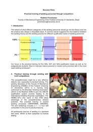
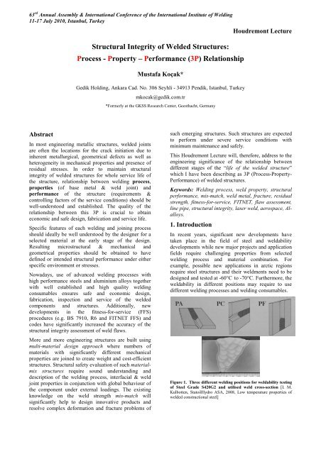
Figure 1. Three different welding positions for weldability testing<br />
of Steel Grade S420G2 and utilised weld cross-section [I. M.<br />
Kulbotten, StatoilHydro ASA, 2008, Low temperature properties of<br />
welded constructional steel]
An example to this case could be seen in Figure 1 where<br />
same steel is welded at different positions using<br />
accordingly different welding process and consumables.<br />
PA refers to submerged arc welding (SAW), PC and PF<br />
are gas shielded flux cored arc welding with different<br />
heat inputs. It is most probable that these different<br />
welding positions (process variations) may lead to<br />
different joint properties and hence welded structure<br />
depending on the loading conditions may differ at<br />
different points.<br />
Therefore, it is essential to consider weld joint<br />
performance an integral part of the welding process and<br />
local properties (strength, notch etc.). For example,<br />
welding process parameters and selected consumables<br />
and base metal grade of line pipes are of major<br />
importance for the integrity of pipelines. The use of<br />
fitness-for-service analysis at the design stage will<br />
enhance the accuracy of the decisions and hence will<br />
improve the productivity, safety of welded fabrication<br />
and integrity respectively.<br />
Weld joints usually exhibits heterogeneous properties<br />
across the joint. This particularly effects the<br />
performance of the structure. For this known reason<br />
weld strength mis-match has been a topic of research<br />
for same time. This paper gives special attention to this<br />
topic.<br />
2. Weld Strength Mis-match<br />
Structural weld joints, particularly bi-material<br />
(dissimilar) joints usually exhibit substantial mechanical<br />
heterogeneity with respect to elastic-plastic deformation<br />
and fracture properties. This heterogeneity is commonly<br />
called as „strength mis-match“ and expressed as yield<br />
strength mis-match;<br />
assisted cracking. In addition to this difficulty, there<br />
exists unintentional strength undermatching in high<br />
strength steel weldments. The weld joints may<br />
unknowingly be undermatched because the base metal<br />
has much higher yield strength than the SMYS<br />
(specified minimum yield strength). It should be noted<br />
that the undermatched welds can have a significant<br />
effect on the strength level, resistance to fracture and<br />
ductility of welded components. The undermatched<br />
welds are particularly sensitive if the welds operate<br />
under tension perpendicular to the weld seam. If the<br />
undermatched welds are loaded in a direction parallel to<br />
the weld length should present no problem, since the<br />
strain will not localise in the soft weld seam.<br />
Particularly, since early nineties, numerous<br />
investigations have been conducted by the author [e.g<br />
1-6] to describe the effects of mis-matching on the<br />
fracture behaviour and toughness. Two special<br />
international conferences, Mis-match 93 [7] and Mismatch<br />
96 [8] have provided international forum and<br />
showed the significant progress had been made in<br />
this field. For example, currently, unified method to<br />
perform defect assessments in mis-matched welds<br />
exists. In this context, recently developed fitness-forservice<br />
procedure FITNET has provided clear<br />
guidline for assessment for such welds. However,<br />
significant amount of work is still needed,<br />
particularly in the areas of high strength steel<br />
weldments, treatment of HAZ softening and highly<br />
undermatched Al-alloy weldments while extensive<br />
validation cases of proposed approaches as well as<br />
treatment of material-mix (multi-material) structures<br />
are still missing.<br />
M=σ YW /σ YB<br />
Over-Match (OM)<br />
Under-Match (UM)<br />
Where σ YW is the weld metal yield strength and σ YB is<br />
the base metal yield strength. It is referred to as<br />
„overmatching if M>1 and called as „undermatching“ if<br />
M YS W<br />
Under-Matched<br />
B<br />
YS W<br />
YS B < YS W<br />
Figure 2. Schematic description of crack tip plasticity due to<br />
weld strength mis-match. LBW: Laser Beam Welding, FSW:<br />
Friction Stir Welding<br />
2H
63 rd Annual Assembly & International Conference of the International Institute of Welding<br />
11-17 July <strong>2010</strong>, Istanbul, Turkey<br />
Houdremont Lecture<br />
Figure 2. Fracture path deviation into lower strength base metal<br />
of the centre cracked wide plate under tension. The weld metal<br />
exhibits strength overmatching.<br />
It is known that the essence of the strength mis-match<br />
lies on the crack tip plasticity development and effect of<br />
the strength difference between weld and base metals<br />
on the deformation pattern at the crack tip and ahead of<br />
the crack tip (uncracked ligament). Figure 2<br />
schematically showing the principal deformation<br />
patterns of the overmatching and undermatching cases<br />
with weld metal and HAZ cracked bodies as well as two<br />
major governing factors of M and 2H (weld width). The<br />
structural steels (up to some strength level) usually<br />
show overmatching while laser beam [9,11] and friction<br />
stir welded (FSW) high strength Al-alloys usually<br />
exhibit undermatching situations [4, 8]. Due to rapid<br />
cooling rate, LB welded ferritic steels and Ti-alloy<br />
show high hardness, and hence high degree of<br />
overmatching.<br />
3. Properties of Weldments<br />
3.1 Tensile Properties<br />
Welded joints have heterogeneous mechanical<br />
properties and also exhibit highly heterogeneous<br />
microstructural variations in a local region. Adequate<br />
tensile and fracture toughness testing techniques<br />
consequently should incorporate such highly<br />
heterogeneous mechanical/microstructural features. The<br />
micro-flat-tensile (MFT) test technique [6, 9-11] is<br />
extremely useful to measure tensile properties of HAZ<br />
of multi-pass welds and very thin weld regions such as<br />
laser beam (LB) and electron beam (EB) welds. During<br />
the tensile testing of weld joint, transverse welded<br />
specimens usually fail away from the weld joint, if weld<br />
metal exhibits high strength overmatching, as shown in<br />
Figure.4. The results of such tests will inevitably<br />
provide base metal strength values but with reduced<br />
ductility, due to the presence of high strength zone<br />
within the gauge length. Advanced testing techniques<br />
with the use of image analysis system, it is possible to<br />
monitor the evolution of the plasticity across the<br />
specimen. Figure 5b is illustrating heterogeneous plastic<br />
strain localisation process for the undermatched FSW<br />
containing flat tensile specimen.<br />
Figure 4. Typical strength overmatched flat tensile specimens<br />
failed away from the weld zone.<br />
Micro-hardness variation across the FSW welded 2024<br />
Al-alloy 20 mm thick plate is showing Figure 5a the<br />
heterogeneous nature of the weld joint. During the<br />
testing of flat tensile specimen, one surface of the<br />
specimen was monitored to determine the strain<br />
localisation and hence ductile failure location with<br />
respect to heterogeneous cross-section of the joint. The<br />
images shown in Figure 4b are illustrating and verifying<br />
the indications of the micro-hardness results. The<br />
micro-hardness results have revealed that the centre part<br />
(nugget) of the joint is not the region with lowest<br />
strength, whereas HAZ (or TMHAZ) regions,<br />
particularly retreating side of the joint may have lowest<br />
strength and hence failure location. Indeed, during the<br />
tensile testing of the specimens of the EU project<br />
WAFS) of joint failed due to localisation of the plastic<br />
strain. The reason for this heterogeneity of the joint<br />
with respect to advancing and retreating sides of the<br />
FSW process is due to the temperature distribution<br />
during the process.<br />
a)
(b)<br />
Figure 5. Microhardness and tensile testing of strength<br />
undermatched Al-alloy 2024 FSW joint.<br />
a) Micro-hardness distribution at different depths of the FSW<br />
weld joint of 2024 Al-alloy<br />
b) ARAMIS images of the FSW joint during the tensile testing of<br />
the joint. Images are showing at different stress levels<br />
corresponding strain distributions. [EU project WAFS]<br />
Figure 6 is showing the specimen extraction technique<br />
from EB welded material for determination of local<br />
tensile properties of the weld joint. The micro-flattensile<br />
specimens are 0.5 mm thick and 2.0 mm wide<br />
and most suitable for determination of mis-match level<br />
for HAZ regions of high strength steels where HAZ<br />
softening usually occur.<br />
Furthermore, this technique can be applied to determine<br />
the mechanical property gradient of the surface treated<br />
components which usually exhibit high degree of<br />
strength mis-match. Figure 7 is illustrating the specimen<br />
extraction of laser surface cladded (hard layer) heavy<br />
section cast material (CuAl10Ni5Fe5) to determine the<br />
property gradient of the surface layer and substrate in<br />
thickness direction. This novel testing technique<br />
provides all needed tensile properties and their<br />
variations, associated with microhardness gradient, as<br />
shown in Figure 8.<br />
Figure 6. Extraction of micro flat tensile specimens from EB weld<br />
[10]<br />
Furthermore, this technique was applied to determine<br />
the tensile property variation of bi-material (2024 and<br />
6056) FSW welds of aerospace Al-alloys. Figure 9 is<br />
showing the yield and tensile strength in combination of<br />
micro-hardness distributions across the FSW joint<br />
between two different Al-alloys.<br />
Strength mis-matching between weld metal and base<br />
metal is not always control the plastic deformation and<br />
hence fracture of the weld joint. The weld joints of the<br />
high strength steels may exhibit lower strength at the<br />
heat affected zones (HAZ softening) and this leads to<br />
strain localization under high external loading and<br />
hence show lower resistance to fracture at this location.<br />
An example for the HAZ softening is shown in Figure<br />
10<br />
Figure 7. Micro flat tensile specimens and standard round tensile<br />
specimen extracted from laser surface cladded thick section<br />
material<br />
Figure 8. Microhardness and yield strength (red solid symbols) variations obtained from laser claded (surface hard layer) cast material and<br />
principle illustration of the loading type of the micro-flat tensile specimens
63 rd Annual Assembly & International Conference of the International Institute of Welding<br />
11-17 July <strong>2010</strong>, Istanbul, Turkey<br />
Houdremont Lecture<br />
Figure 9. Distribution of the micro-hardness, yield strength and tensile strength values across the friction stir welded dissimilar aerospace<br />
grade Al-alloys (2024 and 6056) butt-joint. The tensile properties are determined by testing of 0.5 mm thick micro-flat tensile specimens. [EU<br />
project WAFS]<br />
Figure 10. Distribution of yield and tensile strengths across the APIX80 pipeline steel (14.0 mm thick) weld (5 layer) showing HAZ softening.<br />
The values were obtained by testing of 0.5 mm thick micro-flat-tensile specimens (46 of them) extracted across the weld joint at the GKSS.
. .<br />
In the absence of yield strength value (and full stressstrain<br />
curves) of narrow HAZ zone of high strength<br />
pipeline steel welds, a flaw assessment will use the base<br />
metal properties will then be potentially unsafe.<br />
Therefore, it is recommended to obtain full stress-strain<br />
curves of all regions of the weld joint if complex mismatch<br />
situation is of a concern, as demonstrated in<br />
Figure 10.<br />
3.2 Fracture Toughness Determination of Strength<br />
Mis-matched Welds<br />
Strength mis-match affects the constraint conditions<br />
near the crack tip, and hence effects of mis-match on<br />
the fracture toughness properties are to be expected.<br />
During the fracture toughness testing of very narrow<br />
weld metal zones (laser and electron beam welds, or<br />
HAZ regions) crack path deviation occurs towards<br />
lower strength regions as shown in Figure 11 below.<br />
Hence, the toughness value generated from such<br />
specimens will not represent “intrinsic fracture<br />
toughness” properties of the zone of interest. This<br />
situation is a consequence of the remote plasticity<br />
development in the neighbouring base metal, as<br />
illustrated in Figure 2 and hence obtained fracture<br />
toughness values are meaningless. It is obvious that<br />
plastically heterogeneous interfaces (both sides of the<br />
narrow fusion zone with much lower strength level than<br />
fusion zone) near to the crack tips experience high<br />
strain concentrations and this often leads to crack<br />
kinking out of the high strength but lower toughness<br />
region as illustrated in Figure 11.<br />
Figure 11. Two types of fracture path deviations into the lower<br />
strength base metal regions during the fracture toughness testing<br />
of highly overmatched laser beam welds of ferritic steels [12, Doc.<br />
X-F-078-98]<br />
homogeneous A specimen<br />
A<br />
R p0.2 =320Mpa<br />
homogeneous B specimen<br />
B<br />
R p0.2 =80Mpa<br />
B<br />
A<br />
R p0.2 =80Mpa<br />
8mm<br />
50mm<br />
overmatched specimen undermatched specimen<br />
a/W=0.5, Thickness=5mm<br />
CTOD (δ 5 ), mm<br />
0.8<br />
0.6<br />
0.4<br />
UM: M=0.25<br />
a/W=0.5<br />
2H/(W-a)=0.32<br />
CTOD (δ 5 ), mm<br />
0.8<br />
0.6<br />
0.4<br />
OM: M=4.0<br />
a/W=0.5<br />
2H/(W-a)=0.32<br />
0.2<br />
Homogeneous A<br />
Undermatching<br />
0.2<br />
Homogeneous B<br />
Overmatching<br />
0 0 1 2 3<br />
∆a, mm<br />
0 0 1 2 3<br />
∆a, mm<br />
Figure 12. CTOD δ5-R-curves for highly over- and undermatched model weldments to demonstrate the geometry independency of the local<br />
CTOD measurement technique. Here, homogeneous means all weld metal SENB specimen [8]
63 rd Annual Assembly & International Conference of the International Institute of Welding<br />
11-17 July <strong>2010</strong>, Istanbul, Turkey<br />
In this context, mis-match adjusted toughness<br />
evaluation methodology need to be used to<br />
compensate the mis-match induced constraint on<br />
toughness. Alternatively, fracture toughness can be<br />
obtained directly at the crack tip, using clip or noncontact<br />
displacement measurement/monitoring unit.<br />
One of the techniques in this field is the CTOD-δ5<br />
technique (known as GKSS method) and this uses<br />
direct crack tip opening displacement measurements<br />
as toughness measurement. This toughness<br />
determination technique does not require any mismatch<br />
adjustments. This was demonstrated by using<br />
model weldments (EB welded bi-material SENB<br />
specimens) in Figure 12. The unique R-curves<br />
indicate the fact that local CTOD is not being<br />
influenced with the mechanical properties of the<br />
neighbouring zones.<br />
Houdremont Lecture<br />
The strength level of the weld metal influences the<br />
toughness values of the HAZ. This was demonstrated<br />
by testing of HAZ notched SENB specimens with<br />
shallow and deep notched specimens with using<br />
different wires which produced three distinct levels of<br />
mis-match conditions for the same base metal. Figure<br />
13 is illustrating the effect of weld metal strength on the<br />
measured CTOD values for both lower (a/W=0.1) and<br />
higher constraint (a/W=0.5) specimens. Here, it should<br />
be noted that the local CTOD measurements were made<br />
with clip gauges, which enveloped both weld and<br />
HAZ+BM regions. Inevitably, obtained fracture<br />
toughness values exhibit “apparent HAZ toughness”<br />
values which do not represent intrinsic fracture<br />
toughness properties of the martensitic microstructure<br />
of the HAZ region.<br />
In order to investigate the interfacial fracture between<br />
two highly different metallic materials with respect to<br />
elastic and plastic properties, a bi-material model weld<br />
has been produced using ferritic and austenitic steels<br />
and diffusion bonding process. This project was studied<br />
together with EDF-France to improve understanding of<br />
strength mis-match effect on the fracture toughness.<br />
Figure 14 is showing a round tensile specimen after<br />
testing of a such bi-material specimen where complete<br />
plastic strain accumulated within the weaker austenitic<br />
material part. Figure 15 is presenting the yield strength<br />
properties obtained from testing of micro flat tensile<br />
specimens across the interface. These results are also<br />
compared with the testing of standard round tensile<br />
specimens, as shown in Figure 15.<br />
Figure 13. Effect of weld metal strength on HAZ fracture<br />
toughness for two notch depths [1, 8]<br />
Figure 14. Post-test view of the bi-material round tensile specimen<br />
between ferritic and austenitic steels joined using diffusion<br />
bonding process.<br />
600<br />
Rp0,2 (MPa)<br />
Ferrite<br />
500<br />
400<br />
Austenite<br />
300<br />
Micro Tensile - Part I<br />
Micro Tensile - Part II<br />
Micro Tensile - Average<br />
Round Tensile<br />
200<br />
100<br />
0<br />
Distance to the Interface (m m )<br />
-8 -7 -6 -5 -4 -3 -2 -1 0 1 2 3 4 5 6 7 8<br />
Figure 15. Yield strength values of bi-material joint between austenitic and ferritic steel. The results are generated with the testing of 0.5 mm<br />
thick micro-flat tensile specimens. Bulk material properties are compared with round specimens extracted away from the interface.
Fracture toughness properties of such bi-material<br />
interfaces were determined using SENB specimens<br />
notched at various locations at the vicinity of the bimaterial<br />
interface. The initial notch was located at the<br />
interface (I), ferrite (F) and austenite (A) materials with<br />
constant distance to the interface. Figure 16 is showing<br />
the load vs. CMOD curves obtained from various<br />
specimen types, which are schematically shown with<br />
obtained respective curve. The specimen with<br />
interfacial crack shows immediate effect of higher<br />
strength ferrite material by having higher load carrying<br />
capacity. However, most striking effect of lower<br />
strength material on the fracture toughness of ferrite<br />
material is to prevention (orange colour curve) of<br />
unstable fracture phenomena which is the intrinsic<br />
property of the ferrite (red curve). It appears that the<br />
critical stress state needed for a brittle or unstable crack<br />
initiation is not reached by relaxation of the crack tip<br />
stress by remote plasticity within the austenite.<br />
Accompanying numerical investigations of this bimaterial<br />
system was conducted in France has also<br />
materialised these results. These test results have shown<br />
significant effect of the material properties of<br />
neighbouring zone adjacent to the interface.<br />
Figure 17. Macro section of the sub-interface crack tip (located<br />
into the ferritic-F- steel side of the interface) and strong crack<br />
path deviation towards lower strength (but toughnes) austenitic-<br />
A- material. The figure is also schematically showing the<br />
development of heterogeneous plastic zone at the interface region.<br />
Unstable deformation behaviour of all-ferrite specimen<br />
(shown in red colour curve) becomes stable once<br />
specimen contains soft (lower strength) austenite<br />
material, as orange colour curve demonstrates.<br />
Figure 16. Load vs. CMOD curves of SENB specimens containing bi-material interface. Notch locations were varied, where blue colour SENB<br />
specimen (HoBP-F-7) representing all-ferrite homogeneous specimen while white coloured specimen (HoBP-A-4) refers to all austenite<br />
material.
63 rd Annual Assembly & International Conference of the International Institute of Welding<br />
11-17 July <strong>2010</strong>, Istanbul, Turkey<br />
An extensive development of plasticity at the lower<br />
strength (A) side of the bi-material specimen has<br />
inevitably occurred and crack growth took place taking<br />
into account of least resistance path of the interface<br />
region. Apparently, banded microstructural feature of<br />
the ferritic steel has provided easy crack path to develop<br />
a ductile crack towards lower strength material. These<br />
tests confirm that cracks tend to go into the lower<br />
strength material or zone due to localisation of the<br />
plastic deformation. Fracture toughness values obtained<br />
from such systems will not represent “intrinsic”<br />
material properties of the material where crack tip<br />
originally placed.<br />
Houdremont Lecture<br />
Figure 19. Effect of specimen thickness (B) on fracture toughness<br />
of 38 mm thick steel welded EBW process [Unpublished results<br />
from EU Project ASPOW]<br />
Figure 18. CTOD results for undermatched, matched and<br />
overmatched welds of X80 steel [58].<br />
Further implications of such investigations on model<br />
welds with respect to strength-undermatched systems<br />
are clearly visible. Weld joints of high strength Al-alloy<br />
welds and HAZ softened regions of pipeline steel welds<br />
will be potential failure locations due to the localization<br />
of plastic deformation.<br />
The work of M. Ohata and M. Toyoda [38] was<br />
conducted on the X-80 pipeline steel weldments using<br />
three different wires and analysing the fracture<br />
performance of these welds with surface cracked wide<br />
plates showed the effect of mis-match on the fracture<br />
performance of these welds. Figure 14 is showing the<br />
fracture toughness values for different strength mismatch<br />
conditions. Fracture toughness of the EB welds<br />
(highly overmatched) on 38 mm thick steel was<br />
determined using deep notched SENB specimen to<br />
investigate the effect of specimen thickness (B) on the<br />
fracture toughness of the EB weld fusion zone (FZ).<br />
In addition to the SENB specimens with full plate<br />
thickness of 38 mm, the specimens with 19mm, 9.5 mm<br />
and 4.75 mm thickness were prepared and tested with<br />
identical a/W ratio of 0.5. The results are presented in<br />
Figure 15. The results are showing clearly the effect of<br />
the specimen thickness (B) for a given weld width (2H)<br />
and uncracked ligament (W-a) on the so-called<br />
“apparent fracture toughness”. Although, crack tip was<br />
located at the identical microstructure, reduction of<br />
specimen thickness caused an increase of apparent<br />
toughness (and of scatter) of highly overmatched EB<br />
weld fusion zone. Reduction of the constraint (a<br />
decrease of B/2H or B/(W-a) of the overmatched SENB<br />
specimen, therefore, shows an increase of “apparent<br />
toughness’ which does not represent an “intrinsic<br />
fracture toughness” of the EB weld zone.<br />
3.3 Weld Strength Mis-matched Structures under<br />
Cyclic Loading<br />
Weld strength mis-match principally plays a significant<br />
role under elastic-plastic loading conditions where large<br />
plasticity at the crack tip interacts with different<br />
materials/regions with different mechanical properties.<br />
Once interaction occurs and neighbouring material<br />
influences the evolution of the crack tip stress/strain<br />
state, under external loading, one should expect an<br />
influence of mis-match on the deformation and/or<br />
failure behaviour of the welded component. Numerous<br />
investigations have been conducted to characterise the<br />
constrained plasticity and interface fracture toughness<br />
issues both under small and large-scale yielding<br />
conditions and some of these are reported in the<br />
proceedings of the Mis-match 93 and Mis-match 96<br />
International conferences.
Figure 20. Fatigue crack growth at the fusion line region of the<br />
laser welded Al-alloy which exhibits strong undermatching [24]<br />
Recent studies at the GKSS have focussed on the<br />
strength undermatched structures operating both under<br />
cyclic (constant and variable amplitude) and static<br />
loadings due to the increasingly use of higher strength<br />
materials. The evaluation of fatigue crack in laser beam<br />
and friction stir welded Al-alloy weldments exhibiting<br />
highly strength undermatching conditions have been<br />
investigated. Figure 16 is showing the fatigue crack<br />
growing at the interface (fusion line) between highly<br />
undermatched weld zone and base metal.<br />
Figure 17 a illustrates the fatigue testing of fillet weld<br />
(laser welded skin-stringer joints of airframes) where<br />
horizontal plate (i.e skin) was subjected to the cyclic<br />
loading, as arrows are indicating. When this welded<br />
configuration (with highly strength undermatched joint)<br />
is subjected to fatigue loading, a fatigue crack easily<br />
initiates at the weld toe and advances along the fusion<br />
line, almost parallel to the loading axis and turns into<br />
sheet thickness direction once reaches to the bottom of<br />
the fillet weld where angle of the weld changes. Figure<br />
17b reveals further effect of interface mis-match on the<br />
growing fatigue crack. It appears that as the plastic zone<br />
ahead of the fatigue crack in the soft weld zone touches<br />
the interface (very thin layer of precipitation free soft<br />
zone) with adjacent base metal with higher strength, the<br />
crack kinks to the interface which is not perpendicular<br />
to the loading axis. Continued cyclic loading causes<br />
micro-bifurcation within the soft interface region before<br />
penetrating back into the base metal region. These<br />
examples are clearly showing how strength<br />
heterogeneity both large scale and micro-level operate<br />
to control the advance of the damage and failure of the<br />
component. This kind of information can be utilised to<br />
design effective crack arresters/barriers to achieve<br />
fatigue resistant heterogeneous or bi-material systems.<br />
(a)<br />
(b)<br />
Figure 21. Fatigue crack growth features along the interface of<br />
the laser welded fillet welds of 6xxx series of aerospace Al-alloy, a)<br />
crack initiates at the weld toe and propagates along the fusion line<br />
towards bottom of the fillet weld, b) micrograph of a crack<br />
initiated and advanced within the soft weld, but once reaches to<br />
the interface turns into the much softer interface layer.<br />
Figure 22. Macro-section of the laser spot welded steel Sheets and<br />
strain distribution at the vicinity of the strength overmatched<br />
weld vicinity during the coach peel test [36]<br />
Recently developed advanced high strength steels<br />
(AHSS) are used in car body using resistance spot<br />
welding. This welding technology is being<br />
challenged with developments in laser beam welding.<br />
Laser spot welding for such applications create<br />
highly overmatched spot welds. Figure 18 is showing<br />
a cross section and FE simulation of such joints<br />
under peel testing conditions. Strength overmatch of<br />
weld and smaller weld volume in the lower sheet<br />
determines the failure location in the lower sheet.
63 rd Annual Assembly & International Conference of the International Institute of Welding<br />
11-17 July <strong>2010</strong>, Istanbul, Turkey<br />
Houdremont Lecture<br />
4. Performance of Welds<br />
4.1 Structural Integrity Assessment of Weld<br />
Strength Mis-matched Structures<br />
Structural integrity assessment of components<br />
containing flaw can be conducted to determine one of<br />
the following objectives [27];<br />
- to select suitable material for a given tolearable defect<br />
size, as specified in the design;<br />
- to find the defect tolerance of a welded structure;<br />
- to find if a known defect is acceptable; to determine<br />
or extend the life of a structure;<br />
- to determine cause of failure.<br />
Analysis<br />
Options<br />
Type of tensile<br />
data required<br />
Type of fracture toughness<br />
data required<br />
Other information<br />
0<br />
Basic<br />
YS or SMYS<br />
only<br />
None; Charpy energy only<br />
Relies on correlations; applicable to<br />
ferritic steels only<br />
1<br />
Standard<br />
YS and UTS<br />
Single-point fracture<br />
toughness data or tearing<br />
resistance curves<br />
Based on tensile properties of the weaker<br />
material (typically the PM) and the<br />
fracture toughness of the material in<br />
which the flaw is located<br />
2<br />
Mismatch<br />
YS and UTS of<br />
PM and WM<br />
Single-point fracture<br />
toughness data or tearing<br />
resistance curves<br />
Takes account of strength mismatch;<br />
typically worth applying only if M≥1.1<br />
or M
Assessment for Postulated or Real Flaw<br />
Material & Weld related<br />
input parameters:<br />
Component related<br />
input parameters:<br />
• Tensile data, Fracture<br />
W<br />
•Flaw size, Stress analysis,<br />
a<br />
FITNET FFS ANALYSIS for WELDS<br />
Mis-match ratio<br />
M=YS WM /YS BM<br />
Prediction of critical condition<br />
• Flaw Size<br />
• Stress Level<br />
• Material Property<br />
Figure 24. Flow chart of the Fracture Module of the FITNET FFS Procedure for assessment of the weld flaw.<br />
Defects in welded structures often occur within or<br />
near welds across which tensile properties<br />
significantly vary. As described in previous sections,<br />
this strength mis-match in tensile properties can<br />
affect the plastic deformation pattern of the defective<br />
component, and thus the crack driving force such as<br />
CTOD or J integral. Until research work was<br />
conducted within European project SINTAP [18, 37],<br />
existing defect assessment methods were restricted to<br />
the homogeneous structures. In principle, the<br />
methods for homogenous structures can be applied to<br />
welded structures, if the tensile properties of the<br />
weakest material are used; for instance, for<br />
overmatched welds (M>1), those of the base metal.<br />
However, such a simplified approach can lead to an<br />
unduly conservative result, and thus a FFS<br />
methodology specific to strength mismatched<br />
structures was needed to reduce excessive<br />
conservatism. For this very reason, the SINTAP<br />
Procedure [14, 18, 25, 37] introduced a novel flaw<br />
assessment route for strength mis-match welds.<br />
FITNET FFS Procedure [34, 35] takes over these<br />
routes (Options 2 and 3), Figure 18, for treatment of<br />
conventional multi-pass and advanced (laser and<br />
friction stir) welded structures [25, 31, 32]. The latter<br />
one particularly exhibits significant (up to 50%)<br />
strength undermatching in structural welds used in<br />
aluminium structures of automobile, marine and<br />
aerospace. Figure 20 illustrates the principle of the<br />
FITNET FFS procedure for weldments.<br />
4.2 Mis-match Limit Load<br />
The limit load of the welded structure is the most<br />
crucial parameter for the assessment of the strength<br />
mis-matched welded structures. The limit load of<br />
mis-matched structures differs from those of<br />
homogeneous all base metal or all weld metal<br />
structures or considerations. It lies between these two<br />
limits and controls the evolution of plastic<br />
deformation of the cracked body and hence of the<br />
crack driving force. In classical solid mechanics the<br />
limit load is defined as the maximum load a<br />
component of elastic-ideally plastic material is able<br />
to withstand, above this limit ligament yielding<br />
becomes unlimited. In contrast to this definition, real<br />
materials strain harden with the consequence that the<br />
applied load may increase beyond the value given by<br />
the non-hardening limit load. Sometimes strain<br />
hardening is roughly taken into account by replacing<br />
the yield strength of the material by an equivalent<br />
yield strength (flow strength) in the limit load<br />
equation. In the fitness-for-service (FFS) analysis<br />
procedure FITNET, numbers of limit load solutions,<br />
including newly developed [e.g 13, 15,] are given<br />
in Annex B (Vol II) [35]. The results and recent<br />
developments of SINTAP, BS7910, R6 sources are<br />
used to generate this Annex.<br />
Extensive validation works have been conducted<br />
during the development of the FITNET FFS<br />
Procedure. Some of these investigations can be found<br />
in [21-33]. Furthermore, series of collected case
63 rd Annual Assembly & International Conference of the International Institute of Welding<br />
11-17 July <strong>2010</strong>, Istanbul, Turkey<br />
studies used both during validation and training of<br />
young engineers (Hand outs and lecture notes for<br />
FITNET Training Seminars) and this volume will<br />
also be released soon.<br />
4.3 Weld Strength Mis-match in Steel Pipelines<br />
Extensive investigations have been conducted during<br />
last decades to develop steels, welding technologies<br />
and improvements of design and flaw assessment<br />
guidelines for oil and gas linepipes. These<br />
developments have played a significant role for safe<br />
and economic transportation of natural gas and oil as<br />
well as their field developments. Offshore pipelines<br />
in deep water and long distance gas transporation<br />
produced challenges to develop high strength and<br />
high toughness steels to reduce cost. Up to X120<br />
steel grades have been developed and weldability,<br />
strength mis-match and crack arrest issues were<br />
intensely investigated. The higher strength and<br />
toughness could be reached by the TMCP while<br />
maintaining the good weldability (keeping Ceq at a<br />
suitable level).<br />
It is known that for high strength steels, the potential<br />
for only slightly overmatching or even matching is<br />
more likely to occur than the lower strength steels.<br />
Therefore, whenever the seam weld or girth weld of<br />
the pipe may influence the limit state of the pipe,<br />
weld strength overmatching should be maintained to<br />
start with. This situation appears to be more difficult<br />
to fulfil for X120 (827 MPa) steel pipes and strength<br />
undermatching most likely to occur to satisfy the<br />
toughness and ductility requirements. The steel<br />
producers of X120 grade utilizes a different<br />
microstructural system which is different than<br />
typically used in X80 (quench and temper<br />
microstructure). This in turn may affect the crack<br />
arrest (propagating ductile fracture) behaviour of<br />
such steels and welds.<br />
The strength of linepipe is generally increasing to<br />
reduce the cost and hence the linepipe steel X100 has<br />
been developed by many steel manufacturers using<br />
basically steel chemistries of low C- high Mb, Mo,<br />
Nb (V) microalloyed system with Cu, Ni and Cr<br />
using TMCP technology. However, these steels show<br />
significant HAZ softening and insufficient<br />
overmatching weld metal. During the last decades,<br />
the Y/T (yield to tensile) ratio of pipeline steels has<br />
increased from about 0.80 to 0.9 and above. Today,<br />
pipeline steel standards (e.g API 5L and DIN 17172)<br />
specify a maximum Y/T ratio of 0.93 to ensure<br />
sufficient ductility.<br />
It is often reported that cross-weld tensile properties<br />
determined by the properties of HAZ and weld metal<br />
fractures. Even most of the burst tests reported to be<br />
failed in the weld joints of high strength steel pipes.<br />
It is obvious that designers of pipelines (especially<br />
for strain based applications) are unlikely select weld<br />
metal that is undermatched compared to the base<br />
metal. However, lower strength regions in girth weld<br />
applications can still occur, even when the weld<br />
Houdremont Lecture<br />
metal is overmatched. For example, root pass is often<br />
welded manually with an undermatched consumable<br />
to reduce the risk of hydrogen cracking and promote<br />
better tie-ins. Further, HAZ regions, can exhibit<br />
lower strength then either the weld metal and base<br />
material, as shown in Figure 21.<br />
These results have been presented during recent<br />
pipeline conferences (e.g. Pipe Dreamer’s<br />
Conference, 7-8 Nov. 2002, Yokohama, Japan and<br />
4th Pipeline Technology conference, 9-13 May 2004,<br />
Ostend, Belgium).<br />
It has been also shown [19] that internal pressure of<br />
pipelines can concentrate the strain into low-strength<br />
HAZ of girth welds and an elevation of strain in the<br />
HAZ may not be proportionally increase with the<br />
remote strain to failure. This and similar other<br />
investigations [e.g. 16, 20 see also proceedings of<br />
Pipe dreamers conference and Pipeline technology<br />
conference volumes] have revealed that the structural<br />
significance of local strain elevation topic needs<br />
further investigations.<br />
Figure 25. Hardness distribution across the weld joint of X100<br />
steel, showing HAZ softening (undermatching) while weld metal<br />
exhibit overmatching [16].<br />
Furthermore, high longitudinal strain is one of the most<br />
critical loading conditions experienced by pipeline girth<br />
welds. Such high longitudinal strain in onshore<br />
pipelines is often associated with soil movements<br />
(seismic activity, slope instability etc.). On the<br />
otherhand ofor offshore pipelines, high longitudinal<br />
strains occur during the pipe laying operation (reeling)<br />
and it can be as high as 2-3%. Presently, DNV Offshore<br />
Standard F101 provides substantial guideline for defect<br />
acceptance criteria for under longitidunal strain<br />
condition and this guideline suggest to use BS7910<br />
(Level 3) type of analysis (which is also stress based), if<br />
the accumulated strain is higher than 0.3%. Recently<br />
developed FITNET Fitness for Service Procedure does<br />
not provide a strain based analysis and it is planned to<br />
develop a section addressing to this topic including
analysis of higher grade steel pipes (higher Y/T ratio<br />
materials) and welds (beyond X80) and crack arrest<br />
issues of these steel linepipes.<br />
One of the open issues that need to be dealt with is the<br />
generation of low-constraint fracture toughness values<br />
of the welds and HAZ regions using SENT specimens.<br />
Currently, no solution is available to conduct mis-match<br />
corrected toughness (CTOD and J) testing procedure for<br />
such specimens. Particularly, testing of welds with HAZ<br />
softening (together with weld metal mis-match ratio)<br />
and inclusion of its effect on fracture toughness and<br />
crack driving force estimation (beyond the elastic strain<br />
range) is a complex issue and need further research.<br />
4.4 Weld Strength Undermatching: Welded Thinwalled<br />
Al-alloy Aerospace Structures<br />
Thin-walled components such as used in aerospace and<br />
ship structures are designed to satisfy the damage<br />
tolerance requirements of fatigue and residual strength.<br />
The residual strength of a homogeneous structure is<br />
basically a function of material properties (strength,<br />
toughness etc.), flaw and component geometries as well<br />
as the applied stress. The residual strength assessment<br />
route, therefore, is well established and successfully<br />
used for the riveted (differential) structures in the last<br />
decades. However, assessment of welded (integral)<br />
structures requires detailed information on the local<br />
weld joint (fusion or nugget area and heat affected<br />
zone) properties and weld geometry. This information is<br />
of particular importance if the weld joint exhibits<br />
mechanical heterogeneity (strength mismatch). Joining<br />
of aluminium alloys by friction stir (FSW) or laser<br />
beam welding (LBW) usually produces a weld joint<br />
area having significantly lower strength<br />
(undermatching) than the base metal and this needs to<br />
be taken into account during the structural integrity<br />
assessment. In such welded structures, a lower strength<br />
weld zone may lead to a plastic strain concentration in<br />
the weld joint if it is loaded beyond the yield stress of<br />
the weld material and, hence, to the development of<br />
higher constraint within the weld region due to this<br />
heterogeneous deformation behaviour. Therefore, this<br />
strength mismatch induced complexity needs to be<br />
considered when residual strength analysis is conducted<br />
for such structures. Most of the published validation<br />
cases of the FITNET FFS Procedure deal with strength<br />
overmatched welded thick-walled components where<br />
such welds are common for steel structures. There was<br />
a need to generate new experimental data on highly<br />
undermatched thin-walled structures to provide<br />
validation cases for the FITNET FFS Procedure [35]<br />
where welded structures with strength mismatch can be<br />
assessed. Recently, some validation cases [18, 22-25].<br />
were successfully undertaken with particular interest to<br />
structures welded with advanced joining techniques and<br />
containing strength mismatched welds. The recent<br />
studies, therefore, focussed to the application and<br />
validation of the FITNET FFS Procedure on thin-walled<br />
Al-alloy airframe structures where base metal and LBW<br />
and FSW welded large panel tests provide experimental<br />
data [20]. These investigations need to be extended to<br />
the improvement of damage tolerance performance of<br />
weld strength mis-matched components using so-called<br />
“local engineering” methods. These methods include<br />
modifications of stress state around the weld area by<br />
tailoring of the joint design, welding process and<br />
surface treatments.<br />
The use of adequate and precise input parameters<br />
(based on the experimental observations of the damage<br />
process in the undermatched weld area) is particularly<br />
essential to describe and predict the critical condition in<br />
such structures. The selection of strength and toughness<br />
values to be used in the assessment has significant<br />
implications on the outcome of the analysis and require<br />
new considerations to avoid excessive conservatism of<br />
the predictions.<br />
The treatment of the significantly strength<br />
undermatched thin-walled laser welded Al-alloys both<br />
in butt-joint and stiffened panel configurations have<br />
been investigated and Refs. [18-21] report the results. A<br />
large number of mis-match limit load solutions in the<br />
existing SINTAP procedure is being reviewed and<br />
extended (for example covering clad (bi-material)<br />
structures) and given in Annex B of the second volume<br />
of FITNET FFS.<br />
As an example, two panel results of the strength<br />
undermatched laser welded aerospace Al-alloys<br />
programme [18, 22-24] was selected to demonstrate the<br />
application of FITNET FFS Mis-match Option. Figures<br />
26 and 27 are showing both experimental results of the<br />
panels and comparison with the FITNET predictions<br />
where three different m-values (intends to quantify the<br />
constraint at the crack tip) are used to determine the<br />
sensitivity of the analysis to the m-values (where<br />
δ 5 =K J 2 /m R p0.2 E).<br />
The mis-match yield load and load carrying capacity<br />
level of the cracked panels provide information on the<br />
stress state in the uncracked ligament ahead of the<br />
crack. The failure of the undermatched panel occurred<br />
above the yield load indicating an elastic-plastic regime<br />
but it was far below the tensile strength (approx. 350<br />
kN) of the laser welded joint giving rise to failure<br />
caused by a critical crack tip condition (mis-matched<br />
induced) and not by plastic collapse.<br />
The variation of parameter m shows that for larger m,<br />
the predicted curve becomes stiffer, reaching its<br />
maximum at smaller CTOD values, Figure 27. For<br />
m=2.0, the FITNET prediction is in good agreement<br />
with the experimental failure load as well as the<br />
deformation behaviour. This result shows that strength<br />
undermatching indeed increases the crack tip constraint<br />
to the level of plane strain, although 2.0 mm thick panel<br />
under tension, if it was homogeneous, should operate<br />
under plane-stress condition.<br />
Furthermore, FITNET analysis carried out in [24] for a<br />
much more complex case of reinforced thin panels<br />
containing laser welded multiple stringers. In this case,
63 rd Annual Assembly & International Conference of the International Institute of Welding<br />
11-17 July <strong>2010</strong>, Istanbul, Turkey<br />
Al-alloy panels with three longitudinally laser welded<br />
stringers are tested (test 1 and test 2) and load vs.<br />
CTOD curves are predicted with FITNET FFS<br />
Procedure. Two analysis Options are used, that the<br />
predictions are in good agreement with experimental<br />
results while predictions are remaining at the<br />
conservative side, Figure 27.<br />
The Fracture Module provides a hierarchical assessment<br />
structure (Options) based on the quality of available<br />
input data. Using a higher assessment option ensures a<br />
decrease in conservatism due to an increase of data<br />
quality. Refining the stress analysis of the component<br />
and/or improving the sizing of the flaw under<br />
consideration can also achieve a decrease in<br />
conservatism. The use of Option 3, as shown in Figure<br />
28, proves that the higher analysis Option decreases the<br />
conservatism in predictions.<br />
Houdremont Lecture<br />
Figure 27. Comparison between FITNET FFS Fracture Module<br />
Option 2 (mis-match) predictions and experimentally obtained<br />
load vs. CTOD curves of the thin-walled panels described in Fig.<br />
5. The R-curve was used in the analysis was obtained from small<br />
C(T)50 type fracture toughness specimens [24]<br />
4.5 Current status of the FITNET procedure<br />
Figure 26. Load vs. CTOD curve of the center cracked 760 mm<br />
wide plate. The panel was 2.0 mm thick (weld joint area 2.6mm)<br />
aerospace grade Al-alloy 6013 and contained highly<br />
undermatched 3.0 mm wide laser weld. Furthermore, figure<br />
contains images of the plasticity development at the crack tip and<br />
within the strength undermatched weld. FITNET FFS Procedure<br />
was applied to predict the failure load (point 5) of this thin-walled<br />
and highly mis-matched weld panel under tension [24]<br />
The FITNET FFS procedure is currently available,<br />
Figure 9 to interested parties in the form of a final<br />
document, Revision MK8 [34, 35]. The ultimate aim<br />
remains to publish the procedure (Volumes I and II) as<br />
a CEN document, via a CEN workshop agreement<br />
(CWA 22). It is likely that the volume containing<br />
validation, case studies and tutorials will remain the<br />
intellectual property of the FITNET consortium, and<br />
will be published separately by them. In the meantime,<br />
plans are underway to adopt relevant parts of FITNET<br />
into a future edition of the BS 7910, the UK national<br />
procedure.<br />
Figure 28. FITNET FFS predictions (Option 1 and Option 3) of a<br />
residual strength of laser welded 3-stringer panel with large<br />
central crack (broken central stiffener) [24].
5. Final Remarks<br />
Extensive international efforts have been made to<br />
design and assess the primary welded engineering<br />
structures for safer operation provided framework for<br />
significant progress and numbers of sucess stories to<br />
develop. For this process-property-performance<br />
relationships have been established for various systems.<br />
Research should continue to develop technology and<br />
knowledge applicable to all industrial sectors operating<br />
load-bearing structures, which require safety to be<br />
properly inbuilt in the design and fabrication processes<br />
as well as structural health monitoring, quality<br />
inspections and maintenance to ensure the structural<br />
safety throughout their lifetime.<br />
On the other hand, engineering structures will<br />
increasingly be fabricated using “multi-material design”<br />
principles, which will use different materials with<br />
different mechanical properties to increase the structural<br />
efficiency and for cost and weight reduction purposes.<br />
This will expand the heterogeneous nature of the<br />
components with numbers of dissimilar joint interfaces.<br />
Treatment of defects and cracks in such components<br />
will require new approaches and methodologies. Long -<br />
term research is therefore, needed to develop and<br />
establish the structural safety principles of the hybrid<br />
components increasingly used in various manufacturing<br />
industries. Multi-material design principles should<br />
make use of the existing knowledge on the strength mismatch.<br />
6. Acknowledgements<br />
The author was worked about 25 years at the GKSS<br />
Research Center, Geesthacht, Germany. Hence, the<br />
materials used in this paper have been generated during<br />
these years at the GKSS. Author wish to acknowledge<br />
the valuable contribution of the former colleagues.<br />
References<br />
[1] M. Koçak, M. Es-souni, L. Chen and K.-H. Schwalbe,<br />
“Microstructure and weld metal matching effects on HAZ<br />
toughness”, Proc. of the 8th Int. Conf. OMAE-ASME, The<br />
Hauge, Netherlands, March 19-23, 1989, pp. 623-633.<br />
[2] M. Koçak, J. Knaack and K.-H. Schwalbe, “Fracture behaviour<br />
of undermatched weld joint”, Proc. of the 9th Int. Conf. OMAE-<br />
ASME, Houston, Texas, USA, Feb. 18-23, 1990, Vol. III-Part<br />
B, pp. 453-459.<br />
[3] E. Tschegg, HOK Kirchner and M. Koçak, “Cracks at the<br />
Ferrite-Austenite Interface“, Acta metall. Mater. 38, 469-478,<br />
1990.<br />
[4] B. Petrovski, M. Koçak and S. Sedmak, “Fracture behaviour of<br />
undermatched weld joint with short surface crack”, Proc. of the<br />
10th Int. Conf. OMAE-ASME, Stavanger, Norway, June 23-28,<br />
1991, pp. 101-107.<br />
[5] E. Tschegg, HOK Kirchner and M. Koçak, “Interfacial and Subinterfacial<br />
Cracks in the Copper-Ferrite System“, Engineering<br />
Fracture Mechanics 39, 739-750, 1991.<br />
[6] “Weld Mis-match Effect”, Proc. of the <strong>IIW</strong> Sub Commission X-<br />
F, Doc. X-F-015-94, 28-29 April 1994, IdS, Paris, ed. By M.<br />
Koçak.<br />
[7] Proceeding of the international conference Mis-matching of<br />
welds, ESIS 17 (Ed. by K.-H. Schwalbe and M. Koçak) 1994,<br />
MEP, London, UK.<br />
[8] Proceedings of the international conference on Mis-matching of<br />
interfaces and welds, Ed. by K.-H. Schwalbe and M. Koçak,<br />
1997, GKSS Research Center, Geesthacht, Germany.<br />
[9] G. Cam, S. Riekehr and M. Koçak, “Determination of<br />
mechanical properties of laser welded steel joints with<br />
microtensile specimens”, Proc. of the ASM International<br />
European Conference on Welding and Joining Science and<br />
Technology, 10-12 March 1997, Madrid, Spain, ASM Int., pp.<br />
63-79, also in Doc. X-F-055-97.<br />
[10] M. Koçak G. Cam, S. Riekehr et al, “Micro-tensile test<br />
technique for weldments”, Proc. of the <strong>IIW</strong> Sub Commission X-<br />
F, Weld Mis-match effect”, Doc. X-F-079-98, in Doc. X-F-084-<br />
98, Doc. X-1419-98, Sept. 1998, Hamburg, ed. by M. Koçak.<br />
[11] G. Cam, C. Yeni, S. Erim, V. Ventzke and M. Koçak,<br />
“Investigation into properties of laser welded similar and<br />
dissimilar steel joints”, Journal of Science and Technology of<br />
Welding and Joining, Vol. 3(No.3), 1998.<br />
[12] Weld Mis-match effect, Proc. of the <strong>IIW</strong> Sub Commission X-F,<br />
Doc. X-F-084-98, Doc. X-1419-98, Sept. 1998, Hamburg, ed.<br />
by M. Koçak.<br />
[13] S. Alexandrov and M. Koçak, “Limit load solutions for bilayer<br />
plates with through crack subject to tension”, Engineering<br />
Fracture Mechanics 64, 1999, pp. 507-511.<br />
[14] Y-J Kim, M. Koçak, R.A Ainsworth and U. Zerbst, “SINTAP<br />
defect assessment procedure for strength mis-matched<br />
structures“, Eng. Frac. Mech. 67, 2000, pp. 529-546.<br />
[15] A.K. Motarjemi and M. Koçak, “Tensile yield load solutions for<br />
centre cracked bilayer (clad) plates with and without repair<br />
welds”, Science and Technology of Welding and Joining 2002,<br />
Vol. 7, No. 5, pp. 299-305.<br />
[16] M. Hamada et al, “Tensile properties and deformation<br />
behaviour at the weld position of X100 line pipe steel”, Proc. of<br />
the Int. Conf. Pipe Dreamer’s Conference, 7-8 Nov. 2002,<br />
Yokohama, Japan, pp. 289.<br />
[17] S. Endo et al, “Advances in high-performance linepipes with<br />
respect to stregth and deformability”, Proc. of the Int. Conf.<br />
Pipe Dreamer’s Conference, 7-8 Nov. 2002, Yokohama, Japan,<br />
pp. 273.<br />
[18] E. Seib, M. Koçak and H. Assler, “Fracture Assessment of<br />
Welded Aerospace Al-alloys using SINTAP Route”, DVM-<br />
Bericht 236, Feb. 17-18, 2004, Cologne, Germany.<br />
[19] W. Mohr, “Weld area mis-match and pressure effects in strainbased<br />
design”, Proc. of the 4 th Int. Conf. on Pipeline<br />
Technology, 9-13 May 2004, Ostend, Belgium, Vol. 1, pp. 279.<br />
[20] N. Ishikawa, S. Endo, S. Igi, A. Glower, D. Horsley, M. Ohata<br />
and M. Toyoda, “Ductile fracture behaviour of girth welded<br />
joints and strain based design for high strength linepipes“,<br />
Proc. of the Int. Pipeline Technology Conf., Vol. I, pp. 81-97,<br />
9-13 May 2004, Ostend, Belgium.
63 rd Annual Assembly & International Conference of the International Institute of Welding<br />
11-17 July <strong>2010</strong>, Istanbul, Turkey<br />
Houdremont Lecture<br />
[21] M. Koçak., “Fitness for service analysis of structures using the<br />
FITNET procedure: an overview”, In: Offshore Mechanics and<br />
Arctic Engineering (OMAE 2005). Proc., 24th Int. Conf.,<br />
Halkidiki, Greece, 12-17 June 2005. Publ: New York, NY<br />
10016, USA; ASME; 2005.<br />
[22] E. Seib and M. Koçak, “Fracture Analysis of Strength<br />
Undermatched Welds of Thin-walled Aluminium Structures<br />
using FITNET Procedure”. In: Welding in the World,<br />
November/December 2005, pp. 58-69.<br />
[23] E. Seib and M. Koçak, “Fracture analysis of strength<br />
undermatched welds of thin-walled aluminium structures using<br />
FITNET Procedure”, <strong>IIW</strong>-1709-05, Welding in the World,<br />
49:(11/12), pp. 58-69, 2005.<br />
[24] E. Seib, “Residual strength analysis of LB and FSW aluminium<br />
panels for aerospace applications”, PhD thesis, Tech. Univ.<br />
TUHH, 2005.<br />
[34] FITNET Fitness-for-Service (FFS) – Procedure (Vol. 1), Eds.<br />
M. Koçak, S. Webster, J.J. Janosch, R.A. Ainsworth, R. Koers,<br />
2008, ISBN: 978-3-940923-00-4.<br />
[35] FITNET Fitness-for-Service (FFS) – Annex (Vol. 2), Eds. M.<br />
Koçak, I. Hadley, S. Szavai, Y. Tkach, N. Taylor, 2008, ISBN:<br />
978-3-940923-01-1.<br />
[36] S. Daneshpour, S. Riekehr, M. Koçak and C. Gerritsen,<br />
“Mechanical and fatigue behaviour of laser and resistance spot<br />
welds in advanced high strength steel”, Doc. X-1642-08<br />
[37] SINTAP: http://www.eurofitnet.org/sintap_index.html.<br />
[38] M. Ohata and M. Toyoda, “Fracture performance evaluation of<br />
strength mis-matched welds with surface notch“, <strong>IIW</strong> Doc. X-<br />
1421-98, 1998.<br />
[25] M. Koçak, E. Seib and A. Motarjemi, 2006, “Treatments of<br />
structural welds using FITNET fitness-for-service procedure:<br />
FITNET 06-013”, Proceedings of the International Conference<br />
on Fitness-for-service (FITNET 2006): 17-19 May, Shell<br />
Global Solutions, Amsterdam, The Netherlands (ISBN 978-3-<br />
00-021084-6).<br />
[26] I. Hadley and P. Moore, “Validation of fracture assessment<br />
procedures through full-scale testing: FITNET 06-018”,<br />
Proceedings of the International Conference on Fitness-forservice<br />
(FITNET 2006): 17-19 May, Shell Global Solutions,<br />
Amsterdam, The Netherlands (ISBN 978-3-00-021084-6).<br />
[27] M. Koçak, “FITNET fitness-for-service procedure: an<br />
overview”, FITNET 06-04, in Proceedings of the International<br />
Conference on Fitness-for-service (FITNET 2006): 17-19 May,<br />
Shell Global Solutions, Amsterdam, The Netherlands (ISBN<br />
978-3-00-021084-6).<br />
[28] E. Seib, V. M. Uz and M. Koçak, “Fracture analysis of thinwalled<br />
laser beam and friction stir welded Al-alloys using the<br />
FITNET procedure”, FITNET 06-019, Proceedings of the<br />
International Conference on Fitness-for-service (FITNET<br />
2006): 17-19 May, Shell Global Solutions, Amsterdam, The<br />
Netherlands (ISBN 978-3-00-021084-6).<br />
[29] M. Koçak, “FITNET fitness-for-service procedure: an<br />
overview”, International Institute of Welding, Welding in the<br />
World, vol.51, no.5-6. May-June 2007, pp. 94-105.<br />
[30] M. Koçak., “FITNET fitness-for-service procedure: an<br />
overview”, European Seminar on Pressure Equipment (ESOPE),<br />
Paris, pp. 9-11 Oct, 2007.<br />
[31] I. Hadley, “Validation of the European FITNET fitness-forservice<br />
procedure: incorporation of weld strength mismatch<br />
into fracture assessment (Options 2 and 3)”. TWI Industrial<br />
Members’ report 890/2007.<br />
[32] M. Koçak, S. Webster, J.J. Janosch, R.A. Ainsworth and R.<br />
Koers, “Fitness for Service Analysis of Structures using<br />
FITNET Procedure: An overview”, Proc. of the 9 th Int. Conf on<br />
Engineering Structural Integrity: Research, Development and<br />
Application, 15-19 Oct. 2007, Beijing, EMAS Publishing 2007,<br />
Vol. I, pp. 161-179.<br />
[33] I. Hadley, 2008, “Validation of the European FITNET fitnessfor-service<br />
procedure: Use of fracture assessment Option 4”,<br />
TWI Industrial Members’ report 893/2008.