Proceedings Template - WORD - International Journal of Computer ...
Proceedings Template - WORD - International Journal of Computer ...
Proceedings Template - WORD - International Journal of Computer ...

You also want an ePaper? Increase the reach of your titles
YUMPU automatically turns print PDFs into web optimized ePapers that Google loves.
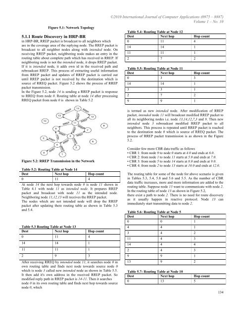
Figure 5.1: Network Topology<br />
5.1.1 Route Discovery in HRP-BR<br />
in HRP-BR, RREP packet is broadcast to all neighbors which<br />
are in the coverage area <strong>of</strong> the replying node. The RREP packet is<br />
broadcast to all neighbor nodes along with intended node. On<br />
receiving RREP packet, neighboring node makes an entry in the<br />
routing table about complete path which has received in RREP. If<br />
neighboring node is not the intended node, it drops RREP packet.<br />
If it is intended node, it adds own id in the received path and<br />
rebroadcast RREP. This process <strong>of</strong> extracting useful information<br />
from RREP packet and updates <strong>of</strong> RREP packet is carried out<br />
until RREP packet is not received by the destination which is<br />
source <strong>of</strong> RREQ packet. Figure 5.2 shows the process <strong>of</strong> RREP<br />
packet transmission.<br />
In the Figure 5.2, node 14 is sending a RREP packet is response<br />
to RREQ from node 0. Routing table at node 14 after processing<br />
RREQ packet from node 0 is shown in Table 5.2<br />
©2010 <strong>International</strong> <strong>Journal</strong> <strong>of</strong> <strong>Computer</strong> Applications (0975 – 8887)<br />
Volume 1 – No. 10<br />
Table 5.4: Routing Table at Node 12<br />
Dest Next hop Hop count<br />
0 11 4<br />
14 14 1<br />
11 11 1<br />
2 7 2<br />
Table 5.5: Routing Table at Node 11<br />
Dest Next hop Hop count<br />
0 3 3<br />
14 14 1<br />
3 3 1<br />
2 7 2<br />
9 9 1<br />
is termed as new intended node. After modification <strong>of</strong> RREP<br />
packet, intended node 11 will broadcast modified RREP packet to<br />
all its neighboring nodes i.e. node 13,14,12,7,3 and 9. Then new<br />
intended node 3 rebroadcast modified RREP packet to all<br />
neighbors. This process is repeated until RREP packet is reached<br />
to the destination node 0 which is source <strong>of</strong> RREQ packet. The<br />
process <strong>of</strong> RREP packet transmission is as shown in the Figure<br />
5.2.<br />
Figure 5.2: RREP Transmission in the Network<br />
Table 5.2: Routing Table at Node 14<br />
Dest Next hop Hop count<br />
0 11 4<br />
At node 14 the next hop towards node 0 is node 11 shown in<br />
Table 4.1 with node 11 as intended node. It prepares RREP<br />
packet and broadcast with node 11 as the intended node.<br />
Neighboring node 11,12,13 will receives the RREP packet.<br />
The nodes which are not intended node will drop the RREP<br />
packet after updating there routing table as shown in Table 5.3<br />
and 5.4.<br />
Table 5.3 Routing Table at Node 13<br />
Dest Next hop Hop count<br />
0 11 4<br />
14 14 1<br />
11 11 1<br />
2 9 3<br />
After receiving RREQ by intended node 11, it searches node 0 in<br />
own routing table and finds next node towards source node 0<br />
which is node 3 called new intended node as shown in Table 5.5.<br />
It then add it's own address in the received RREP packet. So<br />
modified reply path in RREP packet is 14-11. Then it searches<br />
node 0 in its own routing table and finds next hop towards source<br />
node 0, which<br />
Consider few more CBR data traffic as follows<br />
• CBR 1: from node 9 to node 0 starts at 4.0 and ends at 6.0.<br />
• CBR 2: from node 1 to node 11 starts at 5.0 and ends at 7.0.<br />
• CBR 3: from node 5 to node 14 starts at 8.0 and ends at 9.0.<br />
• CBR 4: from node 2 to node 13 starts at 10.0 and ends at 12.0.<br />
The routing table for some <strong>of</strong> the node for above scenario is given<br />
in Tables 5.3, 5.4, 5.8 and 5.6 and 5.5. As the number <strong>of</strong> CBR<br />
data traffic increases, more and more information are added to the<br />
routing table. Suppose node 13 want to communicate with node 2.<br />
In the routing table <strong>of</strong> node 13 as shown in Figure 5.2,<br />
there exist a path to node 2. There is no need for route discovery<br />
as it usually happen in reactive protocol. Node 13 can<br />
immediately start transmitting data to node 2.<br />
Table 5.6: Routing Table at Node 5<br />
Dest Next hop Hop count<br />
0 0 1<br />
4 4 1<br />
3 4 2<br />
11 4 3<br />
14 4 4<br />
2 4 3<br />
9 9 1<br />
13 9 2<br />
Table 5.7: Routing Table at Node 10<br />
Dest Next hop Hop count<br />
0 13 5<br />
134