Five Level Cascaded H-Bridge Multilevel Inverter Using ... - Ijeit.com
Five Level Cascaded H-Bridge Multilevel Inverter Using ... - Ijeit.com
Five Level Cascaded H-Bridge Multilevel Inverter Using ... - Ijeit.com

Create successful ePaper yourself
Turn your PDF publications into a flip-book with our unique Google optimized e-Paper software.
B.<br />
C.<br />
ISSN: 2277-3754<br />
ISO 9001:2008 Certified<br />
International Journal of Engineering and Innovative Technology (IJEIT)<br />
Volume 3, Issue 1, July 2013<br />
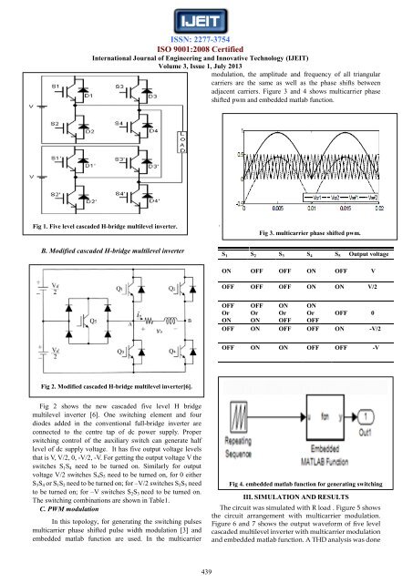
modulation, the amplitude and frequency of all triangular<br />
carriers are the same as well as the phase shifts between<br />
adjacent carriers. Figure 3 and 4 shows multicarrier phase<br />
shifted pwm and embedded matlab function.<br />
D.<br />
E.<br />
F.<br />
G.<br />
H.<br />
I.<br />
J.<br />
K.<br />
Fig 1. <strong>Five</strong> level cascaded H-bridge multilevel inverter.<br />
L.<br />
B. Modified cascaded H-bridge multilevel inverter<br />
.<br />
Fig 3. multicarrier phase shifted pwm.<br />
S 1 S 2 S 3 S 4 S 5 Output voltage<br />
ON OFF OFF ON OFF V<br />
OFF OFF OFF ON ON V/2<br />
OFF<br />
Or<br />
ON<br />
OFF<br />
Or<br />
ON<br />
ON<br />
Or<br />
OFF<br />
ON<br />
Or<br />
OFF<br />
OFF 0<br />
OFF ON OFF OFF ON -V/2<br />
OFF ON ON OFF OFF -V<br />
Fig 2. Modified cascaded H-bridge multilevel inverter[6].<br />
Fig 2 shows the new cascaded five level H bridge<br />
multilevel inverter [6]. One switching element and four<br />
diodes added in the conventional full-bridge inverter are<br />
connected to the centre tap of dc power supply. Proper<br />
switching control of the auxiliary switch can generate half<br />
level of dc supply voltage. It has five output voltage levels<br />
that is V, V/2, 0, -V/2, -V. For getting the output voltage V the<br />
switches S 1 S 4 need to be turned on. Similarly for output<br />
voltage V/2 switches S 4 S 5 need to be turned on, for 0 either<br />
S 3 S 4 or S 1 S 2 need to be turned on; for –V/2 switches S 2 S 5 need<br />
to be turned on; for –V switches S 2 S 3 need to be turned on.<br />
The switching <strong>com</strong>binations are shown in Table1.<br />
C. PWM modulation<br />
In this topology, for generating the switching pulses<br />
multicarrier phase shifted pulse width modulation [3] and<br />
embedded matlab function are used. In the multicarrier<br />
Fig 4. embedded matlab function for generating switching<br />
sequence.<br />
III. SIMULATION AND RESULTS<br />
The circuit was simulated with R load . Figure 5 shows<br />
the circuit arrangement with multicarrier modulation.<br />
Figure 6 and 7 shows the output waveform of five level<br />
cascaded multilevel inverter with multicarrier modulation<br />
and embedded matlab function. A THD analysis was done<br />
439