Five Level Cascaded H-Bridge Multilevel Inverter Using ... - Ijeit.com
Five Level Cascaded H-Bridge Multilevel Inverter Using ... - Ijeit.com
Five Level Cascaded H-Bridge Multilevel Inverter Using ... - Ijeit.com

Create successful ePaper yourself
Turn your PDF publications into a flip-book with our unique Google optimized e-Paper software.
ISSN: 2277-3754<br />
ISO 9001:2008 Certified<br />
International Journal of Engineering and Innovative Technology (IJEIT)<br />
Volume 3, Issue 1, July 2013<br />
<strong>Five</strong> <strong>Level</strong> <strong>Cascaded</strong> H-<strong>Bridge</strong> <strong>Multilevel</strong><br />
<strong>Inverter</strong> <strong>Using</strong> Multicarrier Pulse Width<br />
Modulation Technique<br />
Divya Subramanian, Rebiya Rasheed<br />
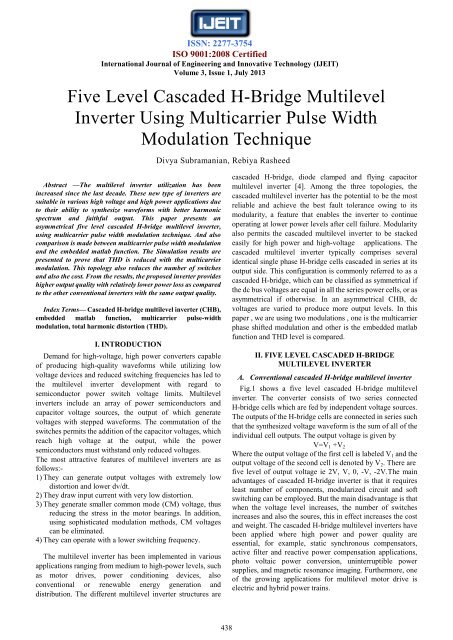
Abstract —The multilevel inverter utilization has been<br />
increased since the last decade. These new type of inverters are<br />
suitable in various high voltage and high power applications due<br />
to their ability to synthesize waveforms with better harmonic<br />
spectrum and faithful output. This paper presents an<br />
asymmetrical five level cascaded H-bridge multilevel inverter,<br />
using multicarrier pulse width modulation technique. And also<br />
<strong>com</strong>parison is made between multicarrier pulse width modulation<br />
and the embedded matlab function. The Simulation results are<br />
presented to prove that THD is reduced with the multicarrier<br />
modulation. This topology also reduces the number of switches<br />
and also the cost. From the results, the proposed inverter provides<br />
higher output quality with relatively lower power loss as <strong>com</strong>pared<br />
to the other conventional inverters with the same output quality.<br />
Index Terms— <strong>Cascaded</strong> H-bridge multilevel inverter (CHB),<br />
embedded matlab function, multicarrier pulse-width<br />
modulation, total harmonic distortion (THD).<br />
I. INTRODUCTION<br />
Demand for high-voltage, high power converters capable<br />
of producing high-quality waveforms while utilizing low<br />
voltage devices and reduced switching frequencies has led to<br />
the multilevel inverter development with regard to<br />
semiconductor power switch voltage limits. <strong>Multilevel</strong><br />
inverters include an array of power semiconductors and<br />
capacitor voltage sources, the output of which generate<br />
voltages with stepped waveforms. The <strong>com</strong>mutation of the<br />
switches permits the addition of the capacitor voltages, which<br />
reach high voltage at the output, while the power<br />
semiconductors must withstand only reduced voltages.<br />
The most attractive features of multilevel inverters are as<br />
follows:-<br />
1) They can generate output voltages with extremely low<br />
distortion and lower dv/dt.<br />
2) They draw input current with very low distortion.<br />
3) They generate smaller <strong>com</strong>mon mode (CM) voltage, thus<br />
reducing the stress in the motor bearings. In addition,<br />
using sophisticated modulation methods, CM voltages<br />
can be eliminated.<br />
4) They can operate with a lower switching frequency.<br />
The multilevel inverter has been implemented in various<br />
applications ranging from medium to high-power levels, such<br />
as motor drives, power conditioning devices, also<br />
conventional or renewable energy generation and<br />
distribution. The different multilevel inverter structures are<br />
cascaded H-bridge, diode clamped and flying capacitor<br />
multilevel inverter [4]. Among the three topologies, the<br />
cascaded multilevel inverter has the potential to be the most<br />
reliable and achieve the best fault tolerance owing to its<br />
modularity, a feature that enables the inverter to continue<br />
operating at lower power levels after cell failure. Modularity<br />
also permits the cascaded multilevel inverter to be stacked<br />
easily for high power and high-voltage applications. The<br />
cascaded multilevel inverter typically <strong>com</strong>prises several<br />
identical single phase H-bridge cells cascaded in series at its<br />
output side. This configuration is <strong>com</strong>monly referred to as a<br />
cascaded H-bridge, which can be classified as symmetrical if<br />
the dc bus voltages are equal in all the series power cells, or as<br />
asymmetrical if otherwise. In an asymmetrical CHB, dc<br />
voltages are varied to produce more output levels. In this<br />
paper , we are using two modulations , one is the multicarrier<br />
phase shifted modulation and other is the embedded matlab<br />
function and THD level is <strong>com</strong>pared.<br />
II. FIVE LEVEL CASCADED H-BRIDGE<br />
MULTILEVEL INVERTER<br />
A. Conventional cascaded H-bridge multilevel inverter<br />
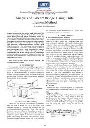
Fig.1 shows a five level cascaded H-bridge multilevel<br />
inverter. The converter consists of two series connected<br />
H-bridge cells which are fed by independent voltage sources.<br />
The outputs of the H-bridge cells are connected in series such<br />
that the synthesized voltage waveform is the sum of all of the<br />
individual cell outputs. The output voltage is given by<br />
V=V 1 +V 2<br />
Where the output voltage of the first cell is labeled V 1 and the<br />
output voltage of the second cell is denoted by V 2 . There are<br />
five level of output voltage ie 2V, V, 0, -V, -2V.The main<br />
advantages of cascaded H-bridge inverter is that it requires<br />
least number of <strong>com</strong>ponents, modularized circuit and soft<br />
switching can be employed. But the main disadvantage is that<br />
when the voltage level increases, the number of switches<br />
increases and also the soures, this in effect increases the cost<br />
and weight. The cascaded H-bridge multilevel inverters have<br />
been applied where high power and power quality are<br />
essential, for example, static synchronous <strong>com</strong>pensators,<br />
active filter and reactive power <strong>com</strong>pensation applications,<br />
photo voltaic power conversion, uninterruptible power<br />
supplies, and magnetic resonance imaging. Furthermore, one<br />
of the growing applications for multilevel motor drive is<br />
electric and hybrid power trains.<br />
438
B.<br />
C.<br />
ISSN: 2277-3754<br />
ISO 9001:2008 Certified<br />
International Journal of Engineering and Innovative Technology (IJEIT)<br />
Volume 3, Issue 1, July 2013<br />
modulation, the amplitude and frequency of all triangular<br />
carriers are the same as well as the phase shifts between<br />
adjacent carriers. Figure 3 and 4 shows multicarrier phase<br />
shifted pwm and embedded matlab function.<br />
D.<br />
E.<br />
F.<br />
G.<br />
H.<br />
I.<br />
J.<br />
K.<br />
Fig 1. <strong>Five</strong> level cascaded H-bridge multilevel inverter.<br />
L.<br />
B. Modified cascaded H-bridge multilevel inverter<br />
.<br />
Fig 3. multicarrier phase shifted pwm.<br />
S 1 S 2 S 3 S 4 S 5 Output voltage<br />
ON OFF OFF ON OFF V<br />
OFF OFF OFF ON ON V/2<br />
OFF<br />
Or<br />
ON<br />
OFF<br />
Or<br />
ON<br />
ON<br />
Or<br />
OFF<br />
ON<br />
Or<br />
OFF<br />
OFF 0<br />
OFF ON OFF OFF ON -V/2<br />
OFF ON ON OFF OFF -V<br />
Fig 2. Modified cascaded H-bridge multilevel inverter[6].<br />
Fig 2 shows the new cascaded five level H bridge<br />
multilevel inverter [6]. One switching element and four<br />
diodes added in the conventional full-bridge inverter are<br />
connected to the centre tap of dc power supply. Proper<br />
switching control of the auxiliary switch can generate half<br />
level of dc supply voltage. It has five output voltage levels<br />
that is V, V/2, 0, -V/2, -V. For getting the output voltage V the<br />
switches S 1 S 4 need to be turned on. Similarly for output<br />
voltage V/2 switches S 4 S 5 need to be turned on, for 0 either<br />
S 3 S 4 or S 1 S 2 need to be turned on; for –V/2 switches S 2 S 5 need<br />
to be turned on; for –V switches S 2 S 3 need to be turned on.<br />
The switching <strong>com</strong>binations are shown in Table1.<br />
C. PWM modulation<br />
In this topology, for generating the switching pulses<br />
multicarrier phase shifted pulse width modulation [3] and<br />
embedded matlab function are used. In the multicarrier<br />
Fig 4. embedded matlab function for generating switching<br />
sequence.<br />
III. SIMULATION AND RESULTS<br />
The circuit was simulated with R load . Figure 5 shows<br />
the circuit arrangement with multicarrier modulation.<br />
Figure 6 and 7 shows the output waveform of five level<br />
cascaded multilevel inverter with multicarrier modulation<br />
and embedded matlab function. A THD analysis was done<br />
439
ISSN: 2277-3754<br />
ISO 9001:2008 Certified<br />
International Journal of Engineering and Innovative Technology (IJEIT)<br />
Volume 3, Issue 1, July 2013<br />
and the result obtained is as shown in figure 8 and 9. A<br />
<strong>com</strong>parison of the multicarrier modulation and<br />
embedded matlab function is presented in table 2.<br />
TABLE 2: COMPARISON OF THD VALUES<br />
Parameters<br />
Multicarrier<br />
modulation<br />
Embedded<br />
matlab function<br />
THD (%) 28.83 30.05<br />
Fig 8. <strong>Five</strong> level cascaded H-bridge multilevel<br />
inverter with multicarrier modulation,<br />
THD=28.83%.<br />
Fig 5 <strong>Five</strong> level cascaded H-bridge multilevel<br />
inverter.<br />
Fig 9. <strong>Five</strong> level cascaded H-bridge multilevel inverter with<br />
embedded matlab function, THD=30.05%.<br />
Fig 6 <strong>Five</strong> level cascaded H-bridge multilevel inverter,<br />
output voltage waveform using multicarrier modulation.<br />
Fig 7 <strong>Five</strong> level cascaded H-bridge multilevel inverter, output<br />
voltage and current waveform using embedded matlab function<br />
IV. CONCLUSION<br />
In this paper, a five level cascaded H-bridge multilevel with<br />
multicarrier pulse width modulation and embedded matlab<br />
function, is presented. The simulation results show that<br />
the total harmonic distortion is low for multicarrier<br />
modulation method. The total harmonic distortion can<br />
be further reduced by using filter circuit. This circuit<br />
also reduces the number of switches and sources.<br />
ACKNOWLEDGMENT<br />
Fore mostly, I would like to express my sincere gratitude to<br />
our Principal: Dr K. S.M Panicker, for his guidance. I am also<br />
thankful to our HOD Dr.Pailo Paul for imparting fundamental<br />
idea, which helped me a lot for my project. I am extremely<br />
thankful to my guide Mrs.Rebiya Rasheed for her guidance<br />
and suggestions; I would also like to thank all my teachers and<br />
my husband Mr.Veneesh C.S who gave their full support and<br />
encouragement for doing this project. I owe my deepest<br />
gratitude to them.<br />
440
ISSN: 2277-3754<br />
ISO 9001:2008 Certified<br />
International Journal of Engineering and Innovative Technology (IJEIT)<br />
REFERENCES<br />
Volume 3, Issue 1, July 2013<br />
[1] Nasrudin Abd. Rahim, Mohamad Fathi Mohamad Elias, Wooi<br />
Ping Hew, IEEE transaction. Industry Electronics, “Design of<br />
filter to reduce harmonic distortion in industrial power<br />
system”, Vol. 60, No: 8, 2943-2956, August 2013.<br />
[2] J. Selvaraj and N. A. Rahim, "<strong>Multilevel</strong> <strong>Inverter</strong> For<br />
Grid-Connected PV System Employing Digital PI Controller,"<br />
IEEE Trans. Ind.Electron., vol. 56, pp. 149-158, 2009.<br />
[3] Naderi and A. Rahmati, "Phase-Shifted Carrier PWM<br />
Technique for General <strong>Cascaded</strong> <strong>Inverter</strong>s," IEEE Trans.<br />
Power Electron. vol. 23, pp. 1257-1269, 2008.<br />
[4] J. Rodriguez, J.-S. Lai, and F. Z. Peng, ―<strong>Multilevel</strong> inverters:<br />
A survey of topologies, controls, and applications,‖ IEEE<br />
Trans. Ind. Electron., vol. 49, no. 4, pp. 724–738, Aug. 2002.<br />
[5] M. Malinowski, K. Gopakumar, J. Rodriguez, and M. A. Pérez,<br />
―A Survey on cascaded multilevel inverters,‖ IEEE Trans.<br />
Ind. Electron., vol. 57, no. 7, pp. 2197-2206, July 2010.<br />
[6] S. J. Park, F. S. Kang, M. H. Lee, and C. U. Kim, ―A new<br />
single-phase five-level PWM inverter employing a deadbeat<br />
control scheme,‖ IEEE Trans. Power Electron., vol. 18, no. 18,<br />
pp. 831–843, May 2003.<br />
[7] N. A. Rahim, and J. Selvaraj, ―Multistring five-level inverter<br />
with novel PWM control scheme for PV application,‖ IEEE<br />
Trans. Ind. Electron., vol. 57, no. 6, pp. 2111-2123, June 2010.<br />
441