Arduino Based Photovore Robot - International Journal of Scientific ...
Arduino Based Photovore Robot - International Journal of Scientific ...
Arduino Based Photovore Robot - International Journal of Scientific ...

Create successful ePaper yourself
Turn your PDF publications into a flip-book with our unique Google optimized e-Paper software.
<strong>International</strong> <strong>Journal</strong> <strong>of</strong> <strong>Scientific</strong> & Engineering Research, Volume 4, Issue 4, April-2013 1003<br />
ISSN 2229-5518<br />
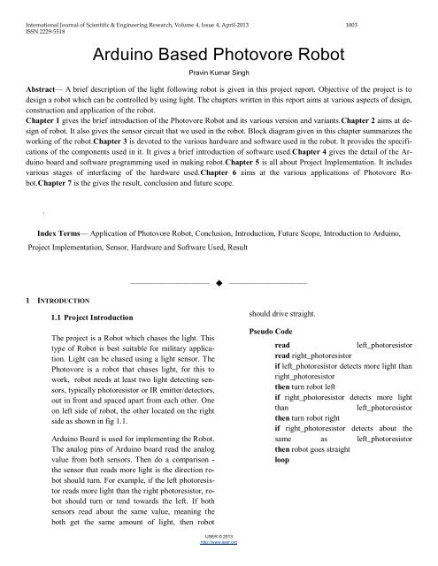
<strong>Arduino</strong> <strong>Based</strong> <strong>Photovore</strong> <strong>Robot</strong><br />
Pravin Kumar Singh<br />
Abstract— A brief description <strong>of</strong> the light following robot is given in this project report. Objective <strong>of</strong> the project is to<br />
design a robot which can be controlled by using light. The chapters written in this report aims at various aspects <strong>of</strong> design,<br />
construction and application <strong>of</strong> the robot.<br />
Chapter 1 gives the brief introduction <strong>of</strong> the <strong>Photovore</strong> <strong>Robot</strong> and its various version and variants.Chapter 2 aims at design<br />
<strong>of</strong> robot. It also gives the sensor circuit that we used in the robot. Block diagram given in this chapter summarizes the<br />
working <strong>of</strong> the robot.Chapter 3 is devoted to the various hardware and s<strong>of</strong>tware used in the robot. It provides the specifications<br />
<strong>of</strong> the components used in it. It gives a brief introduction <strong>of</strong> s<strong>of</strong>tware used.Chapter 4 gives the detail <strong>of</strong> the <strong>Arduino</strong><br />
board and s<strong>of</strong>tware programming used in making robot.Chapter 5 is all about Project Implementation. It includes<br />
various stages <strong>of</strong> interfacing <strong>of</strong> the hardware used.Chapter 6 aims at the various applications <strong>of</strong> <strong>Photovore</strong> <strong>Robot</strong>.Chapter<br />
7 is the gives the result, conclusion and future scope.<br />
.<br />
Index Terms— Application <strong>of</strong> <strong>Photovore</strong> <strong>Robot</strong>, Conclusion, Introduction, Future Scope, Introduction to <strong>Arduino</strong>,<br />
Project Implementation, Sensor, Hardware and S<strong>of</strong>tware Used, Result<br />
—————————— ——————————<br />
1 INTRODUCTION<br />
1.1 Project Introduction<br />
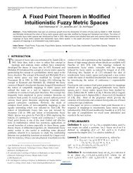
The project is a <strong>Robot</strong> which chases the light. This<br />
type <strong>of</strong> <strong>Robot</strong> is best suitable for military application.<br />
Light can be chased using a light sensor. The<br />
<strong>Photovore</strong> is a robot that chases light, for this to<br />
work, robot needs at least two light detecting sensors,<br />
typically photoresistor or IR emitter/detectors,<br />
out in front and spaced apart from each other. One<br />
on left side <strong>of</strong> robot, the other located on the right<br />
side as shown in fig 1.1.<br />
<strong>Arduino</strong> Board is used for implementing the <strong>Robot</strong>.<br />
The analog pins <strong>of</strong> <strong>Arduino</strong> board read the analog<br />
value from both sensors. Then do a comparison -<br />
the sensor that reads more light is the direction robot<br />
should turn. For example, if the left photoresistor<br />
reads more light than the right photoresistor, robot<br />
should turn or tend towards the left. If both<br />
sensors read about the same value, meaning the<br />
both get the same amount <strong>of</strong> light, then robot<br />
should drive straight.<br />
Pseudo Code<br />
read<br />
left_photoresistor<br />
read right_photoresistor<br />
if left_photoresistor detects more light than<br />
right_photoresistor<br />
then turn robot left<br />
if right_photoresistor detects more light<br />
than<br />
left_photoresistor<br />
then turn robot right<br />
if right_photoresistor detects about the<br />
same as left_photoresistor<br />
then robot goes straight<br />
loop<br />
IJSER © 2013<br />
http://www.ijser.org
<strong>International</strong> <strong>Journal</strong> <strong>of</strong> <strong>Scientific</strong> & Engineering Research, Volume 4, Issue 4, April-2013 1004<br />
ISSN 2229-5518<br />
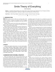
1.4 <strong>Photovore</strong>, Split Brain Approach<br />
This algorithm works without comparison <strong>of</strong> photoresistor<br />
values. Instead, just command the right motor based on<br />
light from the left sensor, and the left motor with only data<br />
from the right sensor. You can also get interesting variations<br />
by reversing the sensors for a cross-brain algorithm<br />
shown in fig 1.3.1.<br />
1.2 Object Avoidance<br />
Fig. 1.1.1 Light detection by sensor<br />
By using the same exact code, and same exact robot, by<br />
doing a small modification we can give <strong>Photovore</strong> the ability<br />
to avoid objects. By bending photoresistor downwards,<br />
and close to the ground, depending on the lighting, objects<br />
will all cast shadows onto the ground. Avoiding darkness,<br />
your <strong>Photovore</strong> robot is naturally an object avoider. Of<br />
course if the lighting shines directly onto an object, or if we<br />
have dark floors with white walls, it might not work so<br />
well. But its easy and it will work... For making a line following<br />
robot, make a <strong>Photovore</strong>, point the photoresistor<br />
towards the ground, and space the photoresistor so that the<br />
distance is less than the width <strong>of</strong> the white line. Exactly<br />
same algorithm can be used.<br />
1.3 <strong>Photovore</strong> Algorithm Improved<br />
This algorithm does the same as the original, but instead <strong>of</strong><br />
case-based it works under a more advanced Fuzzy Logic<br />
control algorithm. Our robot will no longer just have the<br />
three modes <strong>of</strong> turn left, turn right, and go forward.<br />
Pseudo code:<br />
Readleft_photoresistor<br />
read right_photoresistor<br />
right_motor=(right_photoresistorleft_photoresistor)<br />
* arbitrary_constant<br />
loop<br />
Pseudo code:<br />
1.5 Photophobe<br />
Readleft_photoresistor<br />
read right_photoresistor<br />
moveleft_wheel_speed=right_photoresistor<br />
*arbitrary_constant<br />
moveright_wheel_speed=<br />
left_photoresistor * arbitrary_constant<br />
loop<br />
Fig 1.4.1 Split brain approach<br />
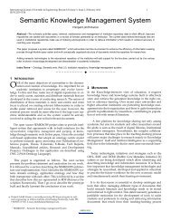
The Photophobe robot is a robot that runs away from light<br />
instead <strong>of</strong> chases light. There are two ways to do this. The<br />
first is simply to reverse the left and right photoresistor, so<br />
that the left sensor is on the right side, and the right sensor<br />
is on the left side. With no changes <strong>of</strong> code, it will avoid<br />
light as shown in the fig 1.5.1.<br />
IJSER © 2013<br />
http://www.ijser.org
<strong>International</strong> <strong>Journal</strong> <strong>of</strong> <strong>Scientific</strong> & Engineering Research, Volume 4, Issue 4, April-2013 1005<br />
ISSN 2229-5518<br />
Fig 1.5.1 Photophobe schematic<br />
readleft_photoresistor<br />
read right_photoresistor<br />
if left_photoresistor detects more light than<br />
right_photoresistor<br />
then turn robot right<br />
if right_photoresistor detects more light<br />
thanleft_photoresistor<br />
then turn robot left<br />
if right_photoresistor detects about the same<br />
asleft_photoresistor<br />
then robot goes straight<br />
loop<br />
The solar panels used today are mostly stationary and do<br />
not have the ability to grasp all the energy <strong>of</strong> the sun because<br />
<strong>of</strong> its inability to shift its position according to the<br />
movement <strong>of</strong> the sun. Because <strong>of</strong> the still stature <strong>of</strong> the<br />
harnessing methods used today it may not be able to receive<br />
the best part <strong>of</strong> the energy which is hitting the surface<br />
<strong>of</strong> the earth. The machine which has been designed (<strong>Photovore</strong>)<br />
for this particular job has the ability <strong>of</strong> detecting the<br />
presence <strong>of</strong> light in an area and following the path illuminated<br />
by it. This is a really good application <strong>of</strong> an LDR<br />
(light dependent resistor) since it involves the detection <strong>of</strong><br />
light with the help <strong>of</strong> the LDR and the intelligent independent<br />
behavior <strong>of</strong> the machine based on the reception <strong>of</strong> solar<br />
energy.<br />
2 SENSOR<br />
2.1 Sensor Schematic<br />
The sensor that we used in our project is Light Dependant<br />
Resistor (LDR).It is made up <strong>of</strong> Cadmium Selenide (CdS).<br />
CdS is mainly used as a pigment. CdS and Cadmium Selenide<br />
are used in manufacturing <strong>of</strong> photoresistor (light dependent<br />
resistors) sensitive to visible and near infrared<br />
light. The photoresistor is shown in the fig. 2.1.1<br />
1.6 Project Overview<br />
The project uses <strong>Arduino</strong> as the controlling element. It uses<br />
Light Dependent Resistor (LDR).When light comes in the<br />
path <strong>of</strong> sensor then sensor gives +5V to arduino board. This<br />
+5v is detected then arduino board decides to run the robot<br />
by taking left or right turn. If the sensor gives 0v to arduino<br />
board that means there is no light present in it path so it<br />
would be stop until any light is detected.<br />
The two light detector resister are fitted on front <strong>of</strong> robot.<br />
The connection can be given from main circuit to sensor<br />
using simple connecting wires.<br />
Two motors namely right motors and left motors are connected<br />
to driver IC (L293D). L293D is interface with the<br />
arduino board. <strong>Arduino</strong> board sends logic 0& logic1 as per<br />
the programming to driver IC which moves motor left, right<br />
and forward direction.<br />
IJSER © 2013<br />
http://www.ijser.org<br />
Fig. 2.1.1 Internal structure <strong>of</strong> photoresistor<br />
In thin-film form, CdS can be combined with other layers<br />
for use in certain types <strong>of</strong> solar cells. CdS was also one <strong>of</strong><br />
the first semiconductor materials to be used for thin film<br />
Transistors (TFTs). However interest in compound semiconductors<br />
for TFTs largely waned after the emergence <strong>of</strong><br />
amorphous silicon technology in the late 1970s.<br />
2.1.1 Sensor Behavior<br />
It exhibits photoconductivity. It can also be referred as photoconductor.<br />
Its resistance decreases with increasing light<br />
intensity and vice versa. In bright light its resistance can go<br />
down to few ohm.IN dark, its resistance goes in the range
<strong>International</strong> <strong>Journal</strong> <strong>of</strong> <strong>Scientific</strong> & Engineering Research, Volume 4, Issue 4, April-2013 1006<br />
ISSN 2229-5518<br />
<strong>of</strong> mega ohms.<br />
2.1.2. Sensor Circuit<br />
To use them as a sensor, we need to measure the voltage<br />
drop across the resistor with the analog port <strong>of</strong> <strong>Arduino</strong><br />
board (because a change in resistance means a change in<br />
voltage). There are two ways to implement photoresistor:<br />
Voltage Increases with Light<br />
To choose resistor values, solve this equation:<br />
(R*Vin)/(R+Rphoto) = Vout<br />
Fig.2.1.2 a Voltage divider circuit with light<br />
There are three steps to determining what resistor<br />
we should use for R. To do this, we first need to get<br />
out a multi-meter and measure the resistance across<br />
the photoresistor in two situations. The first situation<br />
is the darkest light my robot photoresistor will<br />
see.<br />
The second situation is for the brightest light my<br />
robot will see. Now all we need to do is multiply<br />
both resistance values, then find the square root <strong>of</strong><br />
the total. This is the resistor you should use.<br />
Resistor = sqrt(R_dark*R_bright)<br />
The first photoresistor that we used gave the fol<br />
lowing value:<br />
R photo = 4 KΩ<br />
R dark = 0.8M Ω<br />
R1 = √4 K ohm×0.8M ohm =<br />
5.65KΩ<br />
The second photoresistor that we used gave the<br />
following value:<br />
R photo = 18 KΩ<br />
R dark = 1.8M Ω<br />
R1 = √18 K ohm×1.8M ohm = 5.692KΩ<br />
2.1.3. Sensor Working<br />
Voltage Decreases with Light<br />
To choose resistor we solved this equation<br />
(Rphoto*Vin)/(Rphoto+R) = Vout<br />
A photoresistor is made <strong>of</strong> a high resistance<br />
semiconductor. If light falling on the device<br />
is <strong>of</strong> high enough frequency, photons absorbed<br />
by the semiconductor give bound electrons enough<br />
energy to jump into the conduction band. The resulting<br />
free electron (and its hole partner) conduct<br />
electricity, thereby lowering resistance.<br />
Fig2.1.2.b Measuring resistance in dark<br />
Solving the Equations to<br />
mine Resistance, R:<br />
IJSER © 2013<br />
http://www.ijser.org<br />
A photoelectric device can be either intrinsic or<br />
extrinsic. An intrinsic semiconductor has its<br />
own charge carriers and is not an efficient semiconductor,<br />
e.g. silicon. In intrinsic devices the only<br />
available electrons are in the valence band, and<br />
hence the photon must have enough energy to excite<br />
the electron across the entire band gap. Extrinsic<br />
devices have impurities, also called dopants,<br />
added whose ground state energy is closer to the conduction<br />
band; since the electrons do not have as far to jump,
<strong>International</strong> <strong>Journal</strong> <strong>of</strong> <strong>Scientific</strong> & Engineering Research, Volume 4, Issue 4, April-2013 1007<br />
ISSN 2229-5518<br />
lower energy photons (i.e., longer wavelengths and lower<br />
frequencies) are sufficient to trigger the device. If a sample<br />
<strong>of</strong> silicon has some <strong>of</strong> its atoms replaced by phosphorus<br />
atoms (impurities), there will be extra electrons available<br />
for conduction. This is an example <strong>of</strong> an extrinsic semiconductor.<br />
Photoresistor are basically photocells.<br />
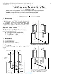
2.2 Block Diagram <strong>of</strong> <strong>Photovore</strong> <strong>Robot</strong>:<br />
Following block diagram shows the working <strong>of</strong> robot<br />
<strong>Arduino</strong> board has 28-pin DIP MCU. It could have any <strong>of</strong><br />
the three MCU chips:<br />
ATmega8 or 8L– 8K ROM, 512B RAM<br />
ATmega168 – 16K ROM, 1024B RAM<br />
ATmega328 – 32K ROM, 512B RAM<br />
All have same number <strong>of</strong> Input /Output Lines - 14 Digital<br />
I/O Lines + 6 Analog Inputs.<br />
The more information <strong>of</strong> ATmega8 is given in the Appendix<br />
A. The board is shown in the fig 3.2.1<br />
Fig 2.2.1 Block diagram <strong>of</strong> <strong>Photovore</strong> <strong>Robot</strong><br />
The block diagram shown above shows the working <strong>of</strong><br />
<strong>Photovore</strong> robot. There are two sensors on the right and left<br />
side <strong>of</strong> the robot placed in front <strong>of</strong> the motor. Both the sensors<br />
are connected to the input pin <strong>of</strong> the <strong>Arduino</strong> board.<br />
The output <strong>of</strong> is taken from the PWM pin <strong>of</strong> the <strong>Arduino</strong>.<br />
This output goes to motor driver which drives the motor.<br />
3.Hardware and S<strong>of</strong>tware Used<br />
3.1. Photoresistors<br />
It has been used as sensor. The purpose <strong>of</strong> two photoresistor<br />
is used for left and right movement <strong>of</strong> the robot. Some<br />
<strong>of</strong> the photoresistors are shown in the fig.3.1<br />
Fig.3.2.1. <strong>Arduino</strong> board<br />
3.3. Motor<br />
Two 12V DC motors are used. The motor has the following<br />
specifications:<br />
It is a geared motor<br />
RPM <strong>of</strong> motor is 200<br />
Fig.3.3.1.Motor<br />
Fig.3.1.1.Photoresistor<br />
3.2. The <strong>Arduino</strong> Board<br />
The <strong>Arduino</strong> board that is used Severino.<br />
IJSER © 2013<br />
http://www.ijser.org<br />
3.4. The Motor Driver<br />
The motor driver shield is used to drive the dc motor. We<br />
cannot get sufficient current from the pin <strong>of</strong> MCU to drive<br />
the motor. So we need a driver. It not only amplifies the<br />
current but also it helps in clockwise and anticlockwise<br />
movement <strong>of</strong> motor. It can drive two dc motor at a time. It<br />
uses motor driver IC L293D IC. For more information
<strong>International</strong> <strong>Journal</strong> <strong>of</strong> <strong>Scientific</strong> & Engineering Research, Volume 4, Issue 4, April-2013 1008<br />
ISSN 2229-5518<br />
about L293D refer to Appendix B. The motor driver is<br />
shown in the fig.3.4.1.<br />
3.5 Battery<br />
Fig.3.4.1 Motor driver<br />
For power supply we have used 12 V dc battery. The battery<br />
is shown in the fig.3.5.1<br />
Its specifications are given below:<br />
It is a rechargeable maintenance free battery<br />
It is sealed lead acid battery<br />
It is a 12v dc battery with current rating 1.2 amp.<br />
For charging current limit should be 0.36 amp.<br />
It is designed to introduce programming to artists and other<br />
newcomers unfamiliar with s<strong>of</strong>tware development<br />
It includes a code editor with features such as syntax highlighting,<br />
brace matching, and automatic indentation, and is<br />
also capable <strong>of</strong> compiling and uploading programs to the<br />
board with a single click. There is typically no need to edit<br />
Makefiles or run programs on the command line. The<br />
<strong>Arduino</strong> IDE comes with a C / C++ library called "Wiring"<br />
(from the project <strong>of</strong> the same name), which makes many<br />
common input/output operations much easier. <strong>Arduino</strong> programs<br />
are written in C/C++, although users only need to<br />
define two functions in order to make a runnable program:<br />
setup() – a function run once at the start <strong>of</strong> a program<br />
which can be used for initializing settings, and<br />
loop () – a function called repeatedly until the board is<br />
powered <strong>of</strong>f.<br />
Fig.3.5.1 Battery<br />
3.6 S<strong>of</strong>tware<br />
The <strong>Arduino</strong> IDE is a cross-platform application written<br />
in Java which is derived from the IDE made for the<br />
Processing programming language and the Wiring project.<br />
IJSER © 2013<br />
http://www.ijser.org
<strong>International</strong> <strong>Journal</strong> <strong>of</strong> <strong>Scientific</strong> & Engineering Research, Volume 4, Issue 4, April-2013 1009<br />
ISSN 2229-5518<br />
NB: Versions <strong>of</strong> the IDE prior to 1.0 saved sketches with<br />
the extension .pde. It is possible to open these files with<br />
version 1.0, you will be prompted to save the sketch with<br />
the .ino extension on save.<br />
Verify<br />
Checks your code for errors.<br />
Upload<br />
Compiles code and uploads it to the <strong>Arduino</strong> I/O<br />
board. See uploading below for details.<br />
Note: If you are using an external programmer, you<br />
can hold down the "shift" key on your computer<br />
when using this icon. The text will change to "Upload<br />
using Programmer"<br />
New<br />
Creates a new sketch.<br />
Open<br />
Presents a menu <strong>of</strong> all the sketches in your sketchbook.<br />
Clicking one will open it within the current<br />
window.<br />
Fig 3.6.1 Snapshot <strong>of</strong> <strong>Arduino</strong> IDE<br />
The toolbar buttons allow you to verify and upload programs,<br />
create, open, and save sketches, and open the serial<br />
monitor:<br />
————————————————<br />
Pravin kumar singh has completed masters degree program in electronics&communication<br />
from DAVV University,Indore, India, MOB-<br />
09717807313. E-mail: pravinsinghsrinet@mail.com<br />
Note: due to a bug in Java, this menu doesn't scroll;<br />
if you need to open a sketch late in the list, use the<br />
File | Sketchbook menu instead.<br />
Save<br />
Saves your sketch.<br />
SerialMonitor<br />
Opens the serial monitor.<br />
Additional commands are found within the five menus:<br />
File, Edit, Sketch, Tools, Help. The menus are context<br />
sensitive which means only those items relevant to the<br />
work currently being carried out are available.<br />
4 Introduction to <strong>Arduino</strong><br />
4.1<strong>Arduino</strong><br />
<strong>Arduino</strong> is a tool for making computers that can sense and<br />
control more <strong>of</strong> the physical world than your desktop computer.<br />
It's an open-source physical computing platform<br />
IJSER © 2013<br />
http://www.ijser.org
<strong>International</strong> <strong>Journal</strong> <strong>of</strong> <strong>Scientific</strong> & Engineering Research, Volume 4, Issue 4, April-2013 1010<br />
ISSN 2229-5518<br />
based on a simple microcontroller board, and a development<br />
environment for writing s<strong>of</strong>tware for the board.<br />
<strong>Arduino</strong> can be used to develop interactive objects, taking<br />
inputs from a variety <strong>of</strong> switches or sensors, and controlling<br />
a variety <strong>of</strong> lights, motors, and other physical outputs. <strong>Arduino</strong><br />
projects can be stand-alone, or they can be communicate<br />
with s<strong>of</strong>tware running on your computer (e.g. Flash,<br />
Processing, MaxMSP.) The boards can be assembled by<br />
hand or purchased preassembled; the open-source IDE can<br />
be downloaded for free.<br />
The <strong>Arduino</strong> programming language is an implementation<br />
<strong>of</strong> Wiring, a similar physical computing plateform, which is<br />
based on the Processing multimedia programming environment.<br />
4.2 <strong>Arduino</strong> Advantages<br />
There are many other microcontrollers and microcontroller<br />
platforms available for physical computing. Parallax Basic<br />
Stamp, Netmedia's BX-24, Phidgets, MIT's Handyboard,<br />
and many others <strong>of</strong>fer similar functionality. All <strong>of</strong> these<br />
tools take the messy details <strong>of</strong> microcontroller programming<br />
and wrap it up in an easy-to-use package. <strong>Arduino</strong><br />
also simplifies the process <strong>of</strong> working with microcontrollers,<br />
but it <strong>of</strong>fers some advantage for teachers, students, and<br />
interested amateurs over other systems:<br />
‣ Inexpensive - <strong>Arduino</strong> boards are relatively inexpensive<br />
compared to other microcontroller platforms.<br />
The least expensive version <strong>of</strong> the <strong>Arduino</strong><br />
module can be assembled by hand, and even the<br />
pre-assembled <strong>Arduino</strong> modules cost less than $50<br />
‣ Cross-platform - The <strong>Arduino</strong> s<strong>of</strong>tware runs on<br />
Windows, Macintosh OSX, and Linux operating<br />
systems. Most microcontroller systems are limited<br />
to Windows.<br />
‣ Simple, clear programming environment - The <strong>Arduino</strong><br />
programming environment is easy-to-use for<br />
beginners, yet flexible enough for advanced users<br />
to take advantage <strong>of</strong> as well. For teachers, it's conveniently<br />
based on the environment will be familiar<br />
with the look and feel <strong>of</strong> <strong>Arduino</strong><br />
‣ Open source and extensible s<strong>of</strong>tware- The <strong>Arduino</strong><br />
s<strong>of</strong>tware and is published as open source tools,<br />
available for extension by experienced programmers.<br />
The language can be expanded through C++<br />
libraries, and people wanting to understand the<br />
technical details can make the leap from <strong>Arduino</strong> to<br />
the AVR C programming language on which it's<br />
based. Similarly, you can add AVR-C code directly<br />
into your <strong>Arduino</strong> programs if you want to.<br />
‣ Open source and extensible hardware - The <strong>Arduino</strong><br />
is based on Atmel's ATMEGA8 and AT-<br />
MEGA168 microcontrollers. The plans for the<br />
modules are published under a Creative Commons<br />
license, so experienced circuit designers can make<br />
their own version <strong>of</strong> the module, extending it and<br />
improving it. Even relatively inexperienced users<br />
can build the breadboard version <strong>of</strong> the module in<br />
order to understand how it works and save money.<br />
4.3 <strong>Arduino</strong> Development Environment<br />
The <strong>Arduino</strong> development environment contains a text editor<br />
for writing code, a message area, a text console, a<br />
toolbar with buttons for common functions, and a series <strong>of</strong><br />
menus. It connects to the <strong>Arduino</strong> hardware to upload programs<br />
and communicate with them. S<strong>of</strong>tware written using<br />
<strong>Arduino</strong> are called sketches. These sketches are written in<br />
the text editor. Sketches are saved with the file extension<br />
.into. It has features for cutting/pasting and for searching/replacing<br />
text. The message area gives feedback while<br />
saving and exporting and also displays errors. The console<br />
displays text output by the <strong>Arduino</strong> environment including<br />
complete error messages and other information. The bottom<br />
right hand corner <strong>of</strong> the window displays the current board<br />
and serial port.<br />
5. Project Implementation<br />
5.1 Connection <strong>of</strong> Motor Driver and <strong>Arduino</strong> Board<br />
Interfacing <strong>of</strong> motor driver with arduino board. Below table<br />
shows the connection <strong>of</strong> respective pin <strong>of</strong> motor driver with<br />
the arduino board . In the fig module 3 is the motor driver<br />
and module 4 is the arduino board.<br />
IJSER © 2013<br />
http://www.ijser.org
<strong>International</strong> <strong>Journal</strong> <strong>of</strong> <strong>Scientific</strong> & Engineering Research, Volume 4, Issue 4, April-2013 1011<br />
ISSN 2229-5518<br />
Motor Driver<br />
+9V<br />
+5V<br />
Gnd<br />
IN1<br />
IN2<br />
IN3<br />
IN4<br />
<strong>Arduino</strong> Board<br />
+9V<br />
+5V<br />
+Gnd<br />
PWM pin 9<br />
digital pin 2<br />
PWM pin 10<br />
digital pin 1<br />
Table 5.1.1 Connection <strong>of</strong> motor driver with arduino<br />
board<br />
5.2 Connection <strong>of</strong> Motor<br />
Now connect the motor pin to the motor driver. The left<br />
motor connected to the pin <strong>of</strong> left motor driver and the right<br />
motor connected to the right pin <strong>of</strong> motor driver. The module<br />
2 is the motor.<br />
5.3. Sensor Interfacing<br />
The fig 5.2.1 shows the interfacing <strong>of</strong> sensor with the arduino<br />
board. There are three terminals in the sensor viz.<br />
Ground, Power supply and output. Sensors are interfaced in<br />
a way such that it controls the motor.Left sensor controls<br />
the right motor and right sensor<br />
controls the left motor.<br />
In the above fig module 5 is the sensor. The interfacing <strong>of</strong><br />
these two is as follows.<br />
Table 5.3.1. Connection <strong>of</strong> sensor with the <strong>Arduino</strong> board<br />
Sensor<br />
+5V<br />
Gnd<br />
Left sensor<br />
Right sensor<br />
<strong>Arduino</strong> Board<br />
+5V<br />
Gnd<br />
analog pin 1<br />
analog pin 0<br />
Fig 5.4.1 Connection <strong>of</strong> power supply and final assembly<br />
The module 1 is power supply. The power supply connected<br />
to the arduino board. In the Fig 5.4.1 the final assembly<br />
is shown.<br />
5.4. Power Supply connection and Final Assembly<br />
IJSER © 2013<br />
http://www.ijser.org
<strong>International</strong> <strong>Journal</strong> <strong>of</strong> <strong>Scientific</strong> & Engineering Research, Volume 4, Issue 4, April-2013 1012<br />
ISSN 2229-5518<br />
5.5 Source Code<br />
Following source code is used for controlling the robot.<br />
/*<br />
program for <strong>Photovore</strong> robot<br />
The circuit:<br />
* Left sensor attached to analog input 1<br />
* Right sensor attached to analog input 0<br />
* One terminal (either one) to ground<br />
* The other terminal to +5V<br />
* Motor wires connected to RIGHT Motor pins on<br />
L293D Board<br />
* Pin D10 - PWM giving signal to IN1 <strong>of</strong> L293D<br />
Board<br />
* Pin D9 - PWM giving signal to IN3 <strong>of</strong> L293D<br />
Board<br />
*/<br />
FWD direction: pin 10 = 1, pin 9 =0<br />
STOP: pin 10 = 0, pin 9 =0<br />
//define then motor driver pin:<br />
#define IN3 9<br />
#define IN4 1<br />
#define IN1 10<br />
#define IN2 2<br />
#define sensor_left 0<br />
#define sensor_right 1<br />
int sensorValue_left=0;<br />
int sensorValue_right=0;// variable to store the value<br />
coming from the sensor<br />
const int threshold = 1023; //define the threshold<br />
void setup()// run once, when the sketch starts<br />
{<br />
//declaration <strong>of</strong> output pin<br />
pinMode(IN1, OUTPUT);<br />
pinMode(IN2 , OUTPUT);<br />
pinMode(IN3, OUTPUT);<br />
pinMode(IN4 , OUTPUT);<br />
}<br />
void loop() {<br />
// read the value from the sensor right:<br />
sensorValue_right = analogRead(sensor_right);<br />
if(sensorValue_right >= threshold)<br />
{<br />
//turn robot right:<br />
}<br />
analogWrite(IN1,sensorValue_right/4);<br />
analogWrite(IN2,0);<br />
sensorValue_left = analogRead(sensor_left);<br />
IJSER © 2013<br />
http://www.ijser.org<br />
// read the value from the sensor left:
<strong>International</strong> <strong>Journal</strong> <strong>of</strong> <strong>Scientific</strong> & Engineering Research, Volume 4, Issue 4, April-2013 1013<br />
ISSN 2229-5518<br />
if (sensorValue_left >= threshold)<br />
{<br />
// turn the robot left:<br />
}<br />
else {<br />
analogWrite(IN3,sensorValue_left/4);<br />
analogWrite(IN4,0);<br />
// move the robot straight:<br />
}<br />
analogWrite(IN1,sensorValue_right);<br />
}<br />
analogWrite(IN2,0);<br />
analogWrite(IN3,sensorValue_left);<br />
analogWrite(IN4,0);<br />
6 Application <strong>of</strong> <strong>Photovore</strong> <strong>Robot</strong><br />
6.1. Smoke detector is a device that detects smoke, typically<br />
as an indicator <strong>of</strong> fire. Commercial, industrial, and<br />
mass residential devices issue a signal to a fire alarm system<br />
while household detectors, known as smoke alarms,<br />
generally issue a local audible or visual alarm from the detector<br />
itself.This home smoke detector circuit warns the<br />
user against fire accidents. It relies on the smoke that is<br />
produced in the event <strong>of</strong> a fire and passes between a bulb<br />
and an LDR, the amount <strong>of</strong> light falling on the LDR decreases.<br />
This type <strong>of</strong> circuit is called optical smoke detector.<br />
Do not use it as a home smoke detector it’s jus for electronic<br />
projects.<br />
This causes the resistance <strong>of</strong> LDR to increase and the voltage<br />
at the base <strong>of</strong> the transistor is pulled high due to which<br />
the supply to (COB) chip on board is completed. The sensitivity<br />
<strong>of</strong> the smoke detector depends on the distance between<br />
bulb and LDR as well as setting <strong>of</strong> preset VR1.thus<br />
by placing the bulb and the LDR at appropriate distances;<br />
one may vary presetVR1to get optimum sensitivity.<br />
IJSER © 2013<br />
http://www.ijser.org<br />
6.2. Laser Computer Tomography Scanner<br />
A laser CT scanner (Fig.5.2.1) based on the principle <strong>of</strong> a<br />
first generation X-ray CT was constructed. This scanner<br />
consisted <strong>of</strong> an aquarium, a turntable with angular graduation,<br />
a red diode laser (~633 nm) as light source, light dependent<br />
resistors (LDR) in series with a resistor as detectors.<br />
A Pentium PC controlled the translate-rotate motion<br />
and also served as the data acquisition system. The aquarium<br />
<strong>of</strong> size 26 x 26 x 20 cm3 was fabricated using Perspex<br />
with wall thickness <strong>of</strong> 3 mm on the laser transmission<br />
sides. The turntable fixed in the aquarium was rotated using<br />
a 4-pole stepper motor. Reduction gears were used such<br />
that the turntable rotated 0.35◦ for each pulse sent to the<br />
stepper motor.<br />
The linear motion <strong>of</strong> the source and the detector was<br />
achieved with two parallel ‘gear and belt ‘arrangements<br />
driven by a single DC motor. The DC motor used for the<br />
linear motion and the stepper motor for the rotational motion<br />
were driven by the PC through the parallel port. The<br />
laser beam was tilted to a small angle (~ 5◦) to avoid reflected<br />
light falling on the detector. The position <strong>of</strong> the detector<br />
was determined by a 10-turn 20K linear potentiometer.<br />
A regulated 10 Volt DC was applied to the potentiometer<br />
and the LDR. The change in resistance was measured as<br />
the variation in the voltage and fed to the PC through a DT<br />
9812 ADC<br />
6.3. Pulse Oximeters<br />
Pulse oximetry is a non-invasive method allowing the<br />
monitoring <strong>of</strong> the oxygenation <strong>of</strong> a patient's hemoglobin.<br />
A sensor is placed on a thin part <strong>of</strong> the patient's body, usually<br />
a fingertip or earlobe, or in the case <strong>of</strong> an infant, across<br />
a foot. Light <strong>of</strong> two different wavelengths is passed through<br />
the patient to a photodetector. The changing absorbance at<br />
each <strong>of</strong> the wavelengths is measured, allowing determination<br />
<strong>of</strong> the absorbances due to the pulsing arterial blood<br />
alone, excluding venous blood, skin, bone, muscle, fat, and<br />
(in most cases) nail polish. With NIRS it is possible to<br />
measure both oxygenated and deoxygenated hemoglobin on<br />
a peripheral scale (possible on both brain and muscle)
<strong>International</strong> <strong>Journal</strong> <strong>of</strong> <strong>Scientific</strong> & Engineering Research, Volume 4, Issue 4, April-2013 1014<br />
ISSN 2229-5518<br />
This method does not require a thin section <strong>of</strong> the patient's<br />
body and is therefore well suited to more universal application<br />
such as the feet, forehead and chest.<br />
A blood-oxygen monitor displays the percentage <strong>of</strong> arterial<br />
hemoglobin in the oxyhemoglobin configuration. Acceptable<br />
normal ranges for patients without COPD with a hypoxic<br />
drive problem are from 95 to 99 percent, those with a<br />
hypoxic drive problem would expect values to be between<br />
88 to 94 percent, values <strong>of</strong> 100 percent can indicate carbon<br />
monoxide poisoning. For a patient breathing room air, at<br />
not far above sea level, an estimate <strong>of</strong> arterial pO 2 can be<br />
made from the blood-oxygen monitor SpO 2 reading.<br />
Pulse oximetry is a particularly convenient noninvasive<br />
measurement method. Typically it utilizes a pair <strong>of</strong> small<br />
light-emitting diodes (LEDs) facing a photodiode through a<br />
translucent part <strong>of</strong> the patient's body, usually a fingertip or<br />
an earlobe. One LED is red, with wavelength <strong>of</strong> 660 nm,<br />
and the other is infrared, 905, 910, or 940 nm. Absorption<br />
at these wavelengths differs significantly between oxyhemoglobin<br />
and its deoxygenated form; therefore, the<br />
oxy/deoxyhemoglobin ratio can be calculated from the ratio<br />
<strong>of</strong> the absorption <strong>of</strong> the red and infrared light. The absorbance<br />
<strong>of</strong> oxyhemoglobin and deoxyhemoglobin is the same<br />
isosbestic point for the wavelengths <strong>of</strong> 590 and 805 nm;<br />
earlier equipment used these wavelengths for correction <strong>of</strong><br />
hemoglobin concentration.<br />
The monitored signal bounces in time with the heart beat<br />
because the arterial blood vessels expand and contract with<br />
each heartbeat. By examining only the varying part <strong>of</strong> the<br />
absorption spectrum (essentially, subtracting minimum absorption<br />
from peak absorption), a monitor can ignore other<br />
tissues or nail polish, (though black nail polish tends to distort<br />
readings and discern only the absorption caused by arterial<br />
blood. Thus, detecting a pulse is essential to the operation<br />
<strong>of</strong> a pulse oximeter and it will not function if there is<br />
none.<br />
6.4 Energy Detection<br />
It can be used in detecting maximum energy received from<br />
the sun. If the solar plate is kept in the one direction whole<br />
day it cannot get maximum intensity <strong>of</strong> the sunlight. So<br />
<strong>Photovore</strong> robot can be used to detect maximum intensity<br />
and it will also change its direction. Hence solar plate can<br />
get maximum intensity whole day.<br />
7.Result, Conclusion & Future Scope<br />
7.1 Result<br />
The photovore is a robot which primarily focuses on the<br />
need for detection <strong>of</strong> the most easily available source <strong>of</strong><br />
energy in our planet. The machine has the capability <strong>of</strong> detecting<br />
the presence <strong>of</strong> solar energy in a particular area and<br />
follows it. The device is totally autonomous and it requires<br />
no human interference or attention.<br />
7.2 Conclusion<br />
The <strong>Photovore</strong> robot has fulfilled all its objectives that<br />
were planned at the time <strong>of</strong> planning.<br />
7.3 Future Scope<br />
This robot may find its application at various situations.<br />
Some <strong>of</strong> the applications are discussed in CHAPTER<br />
6.There are various scope <strong>of</strong> improvement in it. It can be<br />
upgraded to color sensor.<br />
8. Acknowledgments<br />
I would express my deep gratitude to the initiator and the<br />
guide <strong>of</strong> my Project Ms. Kirti Panwar who suggested the<br />
project and guided throughout the course <strong>of</strong> the project. She<br />
was always there to favor and motivate us whenever it was<br />
needed. i would also like thanks to my friend Mr.Mukund<br />
Kumar who worked as a coauthor during all the project.<br />
9.References<br />
1.http://www.robotplatform.com/electronics/photoresistor/p<br />
hotoresistor.html<br />
2.http://www.society<strong>of</strong>robots.com/<br />
3.http://www.arduino.cc/<br />
4.http://www.engineersgarage.com/microcontroller/8051pr<br />
ojects<br />
5.http://www.atmel.com/<br />
6.http://sbolt.home.xs4all.nl/e-fotovoor_prestaties.html<br />
7.http://www.scribd.com/doc/63071973/<strong>Photovore</strong>-<strong>Robot</strong><br />
8.http://www.azom.com/article.aspx?ArticleID=5816<br />
9.http://www.sccs.swarthmore.edu/users/06/adem/engin/e7<br />
2/lab7/<br />
10.http://www.faadooengineers.com/index.php<br />
11. http://www.faadooengineers.com/threads/5219-Relaycoordination-seminar-report-pdf-download.<br />
IJSER © 2013<br />
http://www.ijser.org
<strong>International</strong> <strong>Journal</strong> <strong>of</strong> <strong>Scientific</strong> & Engineering Research, Volume 4, Issue 4, April-2013 1015<br />
ISSN 2229-5518<br />
IJSER © 2013<br />
http://www.ijser.org