Impact Testing of Power LOC Enclosure Part# PL-CII ... - iLECSYS
Impact Testing of Power LOC Enclosure Part# PL-CII ... - iLECSYS
Impact Testing of Power LOC Enclosure Part# PL-CII ... - iLECSYS

Create successful ePaper yourself
Turn your PDF publications into a flip-book with our unique Google optimized e-Paper software.
<strong>Impact</strong> <strong>Testing</strong> <strong>of</strong> <strong>Power</strong> <strong>LOC</strong> <strong>Enclosure</strong><br />
<strong>Part#</strong> <strong>PL</strong>-<strong>CII</strong>/3SW-ESP<br />
PA05/04990<br />
Customer Network Rail Order No: PA05/04990 <strong>iLECSYS</strong> internal<br />
Job description Class 2 <strong>Power</strong> <strong>LOC</strong>, Glass Filled Polycarbonate<br />
Ref: ILS100005<br />
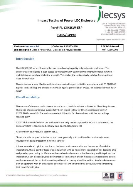
Introduction<br />
The <strong>iLECSYS</strong> FSP series <strong>of</strong> assemblies are based on high quality polycarbonate enclosures. The<br />
enclosures are designed & type tested to withstand very severe environmental conditions while<br />
maintaining an excellent dielectric strength. This makes the units entirely suitable for an outdoor<br />
Class II installation.<br />
The enclosures are certified to withstand mechanical impact to IK09 in accordance with BS EN62262<br />
& prior to machining, the enclosures have an ingress protection <strong>of</strong> IP66/67 in accordance with BS EN<br />
60529.<br />
ClassII suitability.<br />
The nature <strong>of</strong> the non-conductive enclosure is such that it is an ideal solution for Class II equipment.<br />
The range <strong>of</strong> enclosures have successfully been tested to 8kV for 60s in accordance with EN<br />
62208:2003 clause 9.9. The enclosure on test did not in fact break down until the test voltage<br />
reached 18kV.<br />
<strong>iLECSYS</strong> ltd are satisfied that the enclosure is the only realistic option for a Class II solution as, the<br />
enclosure itself is constructed entirely from an insulating material.<br />
As defined in BS7671:2008, section 416.1.<br />
“Paint, varnish, lacquer or similar products are generally not considered to provide adequate<br />
insulation for basic protection in normal service”.<br />
It is our considered opinion that due to the harsh environment that are the nature <strong>of</strong> trackside<br />
installations, that a paint or lacquer coating which MAY be fine on first installation will degrade, chip<br />
and possibly peel during its lifetime and would seriously compromise the safety and integrity <strong>of</strong> the<br />
installation. Such a coating would be impractical to maintain and in most cases impossible to detect<br />
any breakdown <strong>of</strong> the protective coating with only a cursory visual inspection. Any breakdown may<br />
only be apparent with an electrical hi-potential test which would be a difficult & time consuming<br />
task to perform in situe.
Image<br />
<strong>Part#</strong> <strong>PL</strong>-<strong>CII</strong>/3SW-ESP
<strong>Impact</strong> resistance & durability<br />
In order to substantiate the claims made by the enclosure manufacturer, a series <strong>of</strong> mechanical tests<br />
were performed on a completed unit. One <strong>of</strong> the main terminal covers was attacked with various<br />
tools to simulate vandalism or, careless use <strong>of</strong> tools during maintenance activities. The<br />
polycarbonate was very difficult to damage and a determined effort had to be made in order to<br />
cause noticeable damage to the assembly.<br />
Prior to damage<br />
The <strong>PL</strong>-<strong>CII</strong>/3SW-ESP assembly serial#01-000487 prior to damage, with incoming terminal cover<br />
removed to allow connection <strong>of</strong> test probes. The impact testing was carried out on the RH ‘Outgoing<br />
Terminals’ compartment cover shown.
Case 1 – Light Damage<br />
The cover was deliberately scratched with the metal blade <strong>of</strong> a 3mm electrician’s<br />
screwdriver (pictured). The effort required to make the scratch was far greater than damage<br />
that might occur from a simple ‘slip <strong>of</strong> the hand’ or a dropped tool. The scratch produced is<br />
less than 1mm deep and does not penetrate the enclosure.<br />
<br />
<br />
<br />
<br />
IP rating unaffected.<br />
Structural integrity <strong>of</strong> the assembly is maintained.<br />
Maintenance unnecessary.<br />
Class II integrity unaffected.
<strong>Testing</strong> 1.<br />
The damaged cover was surrounded in aluminium foil & the assembly was subjected to an insulation<br />
resistance test at 1000VDC. The addition <strong>of</strong> the foil was to make sure the scratch was connected to<br />
the test probe. The test was successful, the insulation reading being measured at >1000M Ohms.
<strong>Testing</strong> 2.<br />
The damaged cover was surrounded in aluminium foil and a second piece <strong>of</strong> foil was put on the<br />
inside <strong>of</strong> the cover. The assembly was subjected to an insulation resistance test at 1000VDC. The<br />
addition <strong>of</strong> the foil was to make sure the area adjacent to the scratch was connected to the test<br />
probes. The test was successful, the insulation reading being measured at >1000M Ohms.
Case 2 – Deeper & wider gouge.<br />
The cover was scratched further & deliberately gouged with the metal blade <strong>of</strong> a 3mm<br />
electrician’s screwdriver and the blade <strong>of</strong> a 100mm chisel. A 6lb club hammer was used in<br />
conjunction with the chisel to deepen & widen the scratch. Multiple scratch damage was<br />
created; the scratches were <strong>of</strong> varying depths up to and exceeding 1mm in depth but, not<br />
penetrating the enclosure.<br />
<br />
<br />
<br />
<br />
IP rating unaffected.<br />
Structural integrity <strong>of</strong> the assembly is maintained.<br />
Maintenance unnecessary.<br />
Class II integrity unaffected.
<strong>Testing</strong> 3, Tools Used – Deeper & wider gouge.<br />
The damaged cover was surrounded in aluminium foil and a second piece <strong>of</strong> foil was put on the<br />
inside <strong>of</strong> the cover. The assembly was subjected to an insulation resistance test at 1000VDC. The<br />
addition <strong>of</strong> the foil was to make sure the area adjacent to the scratch was connected to the test<br />
probes. The test was successful, the insulation reading being measured at >1000M Ohms.
<strong>Testing</strong> 4.<br />
The damaged cover was again surrounded in aluminium foil and a second piece <strong>of</strong> foil was put on<br />
the inside <strong>of</strong> the cover. The assembly was subjected to an insulation resistance test at 1000VDC. The<br />
addition <strong>of</strong> the foil was to make sure the area adjacent to the scratch was connected to the test<br />
probes. The test was again successful, the insulation reading being measured at >1000M Ohms.
Case 3 – Deliberate damage – non penetrating.<br />
The cover was attacked in the same area with the previous tools, plus, a woodsaw and the<br />
edge <strong>of</strong> a triangular engineers file. The damage continued until a definite scar appeared on<br />
the inside <strong>of</strong> the cover. The gouge was repeatedly scraped, hammered and struck so that<br />
the damage depth was far in excess <strong>of</strong> 1mm and on the limit <strong>of</strong> penetration.<br />
<br />
<br />
<br />
<br />
IP rating unaffected.<br />
Structural integrity <strong>of</strong> the assembly is maintained.<br />
Maintenance unnecessary.<br />
Class II integrity unaffected.
Depth <strong>of</strong> damage<br />
The depth <strong>of</strong> the damage varies but, was measured in excess <strong>of</strong> 1mm.
Inside <strong>of</strong> enclosure<br />
It can be observed in the above picture that the damage is almost penetrating the cover and<br />
has left a noticeable scar on the polycarbonate.
<strong>Testing</strong> 5<br />
The damaged cover was surrounded in aluminium foil & the assembly was subjected to an insulation<br />
resistance test at 1000VDC. The addition <strong>of</strong> the foil was to make sure the deepest scratch was<br />
connected to the test probe. The test was successful, the insulation reading being measured at<br />
>1000M Ohms.
<strong>Testing</strong> 6<br />
The damaged cover was again surrounded in aluminium foil and a second piece <strong>of</strong> foil was put on<br />
the inside <strong>of</strong> the cover. The assembly was subjected to an insulation resistance test at 1000VDC. The<br />
object <strong>of</strong> the test was to make sure the probes were applied to the scarred area <strong>of</strong> polycarbonate.<br />
The test was successful, the insulation reading being measured at >1000M Ohms.
Case 4 – Deliberate penetration.<br />
The images demonstrate the level <strong>of</strong> force required to penetrate the enclosure. It took more than<br />
twenty five blows on the already damaged area to fully penetrate the cover.
Tools used<br />
The images above show that a definite split has been created in the polycarbonate cover.
Conclusions<br />
Despite the crack in the cover, the unit still passed both electrical tests. In reality, <strong>iLECSYS</strong> would<br />
recommend replacement <strong>of</strong> the cover. This level <strong>of</strong> damage would not compromise the Class II<br />
properties <strong>of</strong> the assembly but, would affect the IP rating and allow water to ingress in extreme<br />
circumstances such as flooding or direct driving rain.<br />
It is extremely difficult to damage the polycarbonate enclosures. The material is strong yet, not<br />
brittle. Even repeated blows with a hammer will not cause the cover to chip, crack or shatter.<br />
<strong>iLECSYS</strong> have the utmost confidence in the polycarbonate solution. A metallic enclosure would dent<br />
and deform making the assembly compartment impossible to seal. An added paint or lacquer<br />
coating would chip and/or crack, compromising the safety and Class II integrity <strong>of</strong> the enclosure.<br />
<strong>iLECSYS</strong> are confident that the product will withstand normal service for many, many years and it<br />
has been proved that only deliberate & wilful attempts to damage the enclosure can cause any<br />
lasting damage. The solution <strong>of</strong>fered is suitable for the most extreme & arduous installations and is<br />
almost immune to accidental damage. We conclude that only deliberate vandalism can damage the<br />
product to any real extent.<br />
For any further information, please contact the undersigned.<br />
Sincerely,<br />
Mr. Adrian C. Dante.<br />
Electrical Project Manager – Rail<br />
Adrian Dante│ Electrical Projects │ <strong>iLECSYS</strong> │ Address: Unit 4, Tring Industrial Estate, Upper Icknield<br />
Way, Tring, Hertfordshire, HP23 4JX<br />
Phone: 08444 770 990 │ Main Office: 01442 828 387 │ Fax: 01442 828 399<br />
Email: adrian@ilecsys.co.uk │ Website: www.ilecsys.co.uk │ Company Registration: 03426701<br />
<strong>iLECSYS</strong> would like to remind you that it has Intellectual Property Rights in its designs, many <strong>of</strong> which<br />
have been registered and/or Patents applied for. Drawings sent with this email may not be copied,<br />
altered or distributed to any other parties without the prior written consent <strong>of</strong> <strong>iLECSYS</strong>. <strong>iLECSYS</strong> will<br />
take the matter very seriously if its confidential IPR is misused or compromised in any way