Aerodynamic Design of Unmanned and Scaled Supersonic ...
Aerodynamic Design of Unmanned and Scaled Supersonic ...
Aerodynamic Design of Unmanned and Scaled Supersonic ...
You also want an ePaper? Increase the reach of your titles
YUMPU automatically turns print PDFs into web optimized ePapers that Google loves.
European Congress on Computational Methods in Applied Sciences <strong>and</strong> Engineering<br />
ECCOMAS 2004<br />
P. Neittaanmäki, T. Rossi, S. Korotov, E. Oñate, J. Périaux, <strong>and</strong> D. Knörzer (eds.)<br />
Jyväskylä, 24—28 July 2004<br />
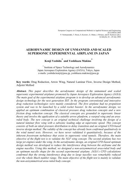
AERODYNAMIC DESIGN OF UNMANNED AND SCALED<br />
SUPERSONIC EXPERIMENTAL AIRPLANE IN JAPAN<br />
Kenji Yoshida * <strong>and</strong> Yoshikazu Makino *<br />
* Institute <strong>of</strong> Space Technology <strong>and</strong> <strong>Aerodynamic</strong>s<br />
Japan Aerospace Exploration Agency (JAXA), Tokyo, Japan<br />
e-mails: yoshida.kenji@jaxa.jp, yoshikazu.makino@jaxa.jp<br />
Key words: Drag Reduction, Arrow Wing, Natural Laminar Flow, Inverse <strong>Design</strong> Method,<br />
Adjoint Method<br />
Abstract. This paper describes the aerodynamic design <strong>of</strong> the unmanned <strong>and</strong> scaled<br />
supersonic experimental airplanes promoted by Japan Aerospace Exploration Agency (JAXA).<br />
The main goal <strong>of</strong> the experimental airplane program is to develop an advanced aerodynamic<br />
design technology for the next generation SST. In the program conventional <strong>and</strong> innovative<br />
drag reduction technologies were mainly considered. The first airplane had no propulsion<br />
system <strong>and</strong> was to be launched by a solid rocket booster. In the aerodynamic design, we<br />
applied an optimum combination <strong>of</strong> classical pressure drag reduction concepts <strong>and</strong> a new<br />
friction drag reduction concept. The classical concepts are grounded in supersonic linear<br />
theory <strong>and</strong> involve the application <strong>of</strong> a suitable arrow planform, a warped wing <strong>and</strong> an arearuled<br />
body. The new concept is an original technical challenge involving the design <strong>of</strong> a<br />
natural laminar flow wing with a subsonic leading edge at supersonic speed. This concept<br />
consists <strong>of</strong> both an ideal pressure distribution to delay transition <strong>and</strong> an original CFD-based<br />
inverse design method. The validity <strong>of</strong> the concept has already been confirmed qualitatively in<br />
the wind tunnel tests. However, we have never validated it quantitatively, because <strong>of</strong> the<br />
inherent freestream turbulence that exists in supersonic wind tunnels. Therefore, the main<br />
objective <strong>of</strong> the flight test is to validate the NLF wing concept. The second airplane has two<br />
large jet engines under the wing. In the aerodynamic design, an original CFD-based optimum<br />
design method was developed to reduce the interference drag between the airframe <strong>and</strong> the<br />
engine nacelles. Using this method, we designed a non-axisymmetrical area-ruled body <strong>and</strong><br />
an optimum nacelle shape for the second experimental airplane. JAXA’s CFD calculations<br />
confirmed that the strong interference drag due to large nacelles was remarkably reduced<br />
over the whole Mach number range. The main objective <strong>of</strong> the flight test is mainly to validate<br />
the non-axisymmetrical area-ruled body concept.<br />
1
K. Yoshida <strong>and</strong> Y. Makino<br />
1 INTRODUCTION<br />
After the development <strong>of</strong> the Concord, the U.S.A. <strong>and</strong> Europe investigated several<br />
advanced technologies for the challenge <strong>of</strong> realizing the development <strong>of</strong> the next generation<br />
SST. In general, the challenge can be undertaken within the framework <strong>of</strong> an international<br />
collaboration. We at Japan have to advance our technology level in order to join the<br />
collaboration <strong>and</strong> support the development.<br />
Japan Aerospace Exploration Agency (JAXA) is promoting the National EXperimental<br />
<strong>Supersonic</strong> Transport (NEXST) program. This program was initiated in 1997 <strong>and</strong> will last<br />
until 2005. It consists <strong>of</strong> fundamental research activity <strong>and</strong> flight test program. The main<br />
objectives <strong>of</strong> the fundamental research activity are to advance present technologies in Japan<br />
<strong>and</strong> to create some innovative technologies for the next generation SST in the future. Since<br />
Japan has high advanced capability in CFD technology, the principal goal is focused on<br />
developing a CFD-based optimum aerodynamic design technology.<br />
In the flight test program, we have designed <strong>and</strong> developed two kinds <strong>of</strong> unmanned <strong>and</strong><br />
scaled experimental airplanes. The main objective <strong>of</strong> the first airplane is mainly to validate<br />
supersonic drag reduction technology by the flight test <strong>of</strong> a pure aerodynamic configuration<br />
without any propulsion system. The main objective <strong>of</strong> the second airplane is to validate the<br />
CFD-based optimum design technology by the flight test <strong>of</strong> a more complicated configuration<br />
with two engines <strong>and</strong> nacelles under the wing.<br />
The first airplane is called “NEXST-1”<br />
airplane <strong>and</strong> will be launched by a solid rocket<br />
booster (see Figure1). The aerodynamic design<br />
<strong>of</strong> the airplane was undertaken in the following<br />
two steps: i) applying the well-known clasical<br />
drag reduction concepts for reducing pressure<br />
drag, <strong>and</strong> ii) designing an original supersonic<br />
natural laminar flow (NLF) wing concept for<br />
reducing friction drag. The final aerodynamic<br />
design <strong>and</strong> production <strong>of</strong> the NEXST-1 airplane<br />
is already completed. The flight test plan is<br />
summarized in Figure 1. The aerodynamic<br />
forces, surface pressures <strong>and</strong> transition data will<br />
Woomera<br />
Separation<br />
Launch<br />
α-sweep at M=2 <strong>and</strong> low<br />
18,000 m<br />
15,000 m<br />
be measured at two α sweep tests. In its production, the severe roughness criterion <strong>of</strong><br />
maximum height within 1 µ m was required for the successful transition measurement.<br />
The second airplane is called “NEXST-2” <strong>and</strong> is a jet-powered vehicle. In the aerodynamic<br />
design <strong>of</strong> the NEXST-2 airplane, first <strong>of</strong> all, the following basic design concepts were<br />
applied: an arrow planform with slightly higher aspect ratio than the NEXST-1 airplane, a<br />
modified warped wing with two embedded nacelles, an NLF wing at inboard, a supersonic<br />
leading edge at outboard. Secondly, an original non-axisymmetrical area-ruled body with an<br />
optimum nacelle configuration was designed using a CFD-based optimum design method<br />
developed in JAXA. This concept was utilized in reducing the interference drag between the<br />
airframe <strong>and</strong> two large nacelles. The basic aerodynamic design <strong>of</strong> the NEXST-2 airplane was<br />
11,000 m<br />
α-sweep at M=2 <strong>and</strong> high<br />
Recovery<br />
Figure 1. Flight test plan <strong>of</strong> NEXST-1 airplane<br />
2
K. Yoshida <strong>and</strong> Y. Makino<br />
completed in the middle <strong>of</strong> 2003. The aim <strong>of</strong> the<br />
flight test will be to ensure the practicality <strong>of</strong><br />
applying the design method to real aircraft<br />
design. The flight test plan <strong>of</strong> the NEXST-2<br />
airplane is summarized in Figure 2. Several<br />
technical data will be measured at supersonic<br />
<strong>and</strong> subsonic flight.<br />
The first flight test <strong>of</strong> the NEXST-1 airplane<br />
was conducted on the 14 th <strong>of</strong> July in 2002.<br />
Unfortunately the test was a failure, because <strong>of</strong><br />
unexpected early separation <strong>of</strong> the booster due<br />
to an electric short on the firing system <strong>of</strong><br />
separation bolts. The failure resulted in the<br />
M=0.8 at H=12 km<br />
NEXST-2 program being frozen until the success <strong>of</strong> the flight test <strong>of</strong> the NEXST-1 airplane.<br />
Since then, we have improved <strong>and</strong> redesigned the whole system. The next flight test is<br />
scheduled for the end <strong>of</strong> 2004. We really do our best to realize the successful fight test <strong>of</strong> the<br />
NEXST-1 airplane.<br />
Present paper describes details <strong>of</strong> the aerodynamic design <strong>of</strong> both experimental airplanes.<br />
2 AERODYNAMIC DESIGN OF NEXST-1 AIRPLANE<br />
In general, we have the following st<strong>and</strong>points in the aerodynamic design <strong>of</strong> the advanced<br />
SST: reducing supersonic drag, reducing sonic boom, improving subsonic aerodynamic<br />
performance, compromising aerodynamics <strong>and</strong> structures, <strong>and</strong> suppressing aerodynamic noise.<br />
However as the first step <strong>of</strong> developing these advanced technologies, we mainly focused on<br />
improving lift-to-drag ratio (L/D) at supersonic <strong>and</strong> subsonic speed in the flight test program,<br />
because improving L/D is the most key technology in all development <strong>of</strong> SST. Furthermore,<br />
reducing sonic boom <strong>and</strong> improving take-<strong>of</strong>f/l<strong>and</strong>ing performance with high lift device are<br />
also important. Therefore, they are investigated as fundamental reserach activities.<br />
In the aerodynamic design <strong>of</strong> the NEXST-1 airplane, main target was placed on reducing<br />
supersonic drag only, because this configuration is clean – that is, it is an aerodynamically<br />
pure shape. Therefore, we can obtain the optimum effect <strong>of</strong> combining several drag reduction<br />
concepts. In the NEXST program, we developed advanced aerodynamic design technology<br />
according to the following philosophy: to design mathematically along the logical process<br />
without any empirical parameters <strong>and</strong> to incorporate some innovative technologies.<br />
To design the NEXST-1 airplane, first <strong>of</strong> all, we had to specify some typical requirements<br />
on an expected real SST aircraft such as fuselage length, volume, tail shape <strong>and</strong> position. We<br />
selected the following dimensions, referring the study [1] <strong>of</strong> JADC (Japan Aircraft<br />
Development Corporation) <strong>and</strong> other foreign papers: M=2 (cruise Mach number), C L =0.1<br />
(cruise lift coefficient), H=15km (flight altitude), S=9000 ft 2 (wing area), L=300 ft (fuselage<br />
length), V=30000 ft 3 (fuselage volume for 300Pax) <strong>and</strong> scaled tail configurations <strong>of</strong> the<br />
Concorde. Then, we selected a scale ratio <strong>of</strong> 11% <strong>of</strong> the real SST aircraft dimensions above.<br />
However, tail cone length <strong>of</strong> the scaled fuselage was slightly extended to keep the<br />
fire-on<br />
take-<strong>of</strong>f<br />
M=1.7 at H=15 km<br />
Test region<br />
separation<br />
data-link<br />
l<strong>and</strong>ing<br />
engine cut-<strong>of</strong>f<br />
X-38 scaled<br />
model<br />
Figure 2. Flight test plan <strong>of</strong> NEXST-2 airplane<br />
3
K. Yoshida <strong>and</strong> Y. Makino<br />
requirement <strong>of</strong> volume capacity for parachute system used in a recovery phase <strong>of</strong> the flight<br />
test. Therefore, the tail shape <strong>of</strong> the scaled airplane is not similar as the real SST aircraft.<br />
2.1 <strong>Design</strong> Concepts<br />
<strong>Supersonic</strong> drag generally consists <strong>of</strong> pressure drag <strong>and</strong> friction drag. The pressure drag is<br />
also divided into lift-dependent drag <strong>and</strong> wave drag due to volume. Furthermore, the liftdependent<br />
drag is composed by vortex drag <strong>and</strong> wave drag due to lift. This drag breakdown is<br />
based on supersonic linear theory [2].<br />
We summarized our design concepts<br />
incorporated in the aerodynamic design <strong>of</strong> the<br />
NEXST-1 airplane in Figure 3. They are i)<br />
Arrow Planform, ii) Warped Wing, iii) Arearuled<br />
Body <strong>and</strong> iv) <strong>Supersonic</strong> NLF Wing. The<br />
concepts <strong>of</strong> i), ii) <strong>and</strong> iii) are well known to be<br />
effective in reducing lift-dependent drag by i),<br />
ii) <strong>and</strong> wave drag due to volume by iii). They<br />
are based on supersonic linear theory <strong>and</strong> their<br />
design procedures were already derived in the<br />
development <strong>of</strong> the Concorde. The concept <strong>of</strong><br />
iv) was originally developed in this program [3].<br />
1. Arrow planform<br />
・AR=2.2(S=10.12 m 2 )<br />
2. Warped Wing<br />
3. Area-ruled body<br />
<strong>Design</strong> point : C L =0.1 @ M=2.0<br />
11.5 m<br />
4. <strong>Supersonic</strong><br />
NLF wing<br />
Recovery system<br />
Figure 3. <strong>Design</strong> concepts <strong>of</strong> NEXST-1<br />
airplane<br />
1) Arrow Planform Concept<br />
In general, a higher aspect ratio is also aerodynamically desirable at supersonic speed.<br />
Furthermore, there is an optimum slenderness ratio in supersonic linear theory [2]. The<br />
slenderness ratio (s/l) <strong>of</strong> a wing planform is defined as a ratio <strong>of</strong> its semi-span length (s) to its<br />
maximum streamwise length (l). However, the planform with such an optimum slenderness<br />
ratio usually has a highly swept leading edge. A higher aspect ratio <strong>and</strong> a highly swept leading<br />
edge generally lead to some structural penalties. Therefore, we need to compromise both the<br />
increase <strong>of</strong> aspect ratio <strong>and</strong> the optimum slenderness ratio, to design a practical wing under<br />
some structural constraints. Arrow planform with subsonic leading edge is well known to be<br />
very effective in compromising. Therefore, the first principle for reducing supersonic drag is<br />
to select an arrow planform with a suitable s/l near the optimum one taking account <strong>of</strong><br />
stractural constraints.<br />
2) Warped Wing<br />
To reduce the lift-dependent drag, one <strong>of</strong> the best ways is to adopt an ideal combination <strong>of</strong><br />
camber <strong>and</strong> twist distribution to realize an optimum load distribution. Such a cambered <strong>and</strong><br />
twisted surface is usually called “warped surface”. Carlson et al developed a numerical<br />
method for estimating drag <strong>and</strong> designing a warped surface in 1974 [4]. They expressed an<br />
optimum load as a combination <strong>of</strong> several prescribed elementary loads, <strong>and</strong> optimized their<br />
combination coefficients by applying variational principle. As a result <strong>of</strong> the optimization,<br />
they obtained an optimum camber <strong>and</strong> twist distribution to realize the lowest lift-dependent<br />
4.72 m<br />
4
K. Yoshida <strong>and</strong> Y. Makino<br />
drag under the limitation <strong>of</strong> design condition <strong>and</strong> planform constraints.<br />
The key point <strong>of</strong> warp design is to suppress theoretical infinite load at leading edge. This<br />
usually leads to a certain leading edge droop to achieve an attached flow condition, because<br />
leading edge separation vortex is induced by local high angle <strong>of</strong> attack due to highly swept<br />
leading edge. This is the second principle for reducing supersonic drag.<br />
3) Area-Ruled Body<br />
According to the supersonic slender body theory [5], wave drag due to volume <strong>of</strong> a<br />
complete aircraft is generally related to so-called supersonic cross sectional area distribution.<br />
This area means the projection <strong>of</strong> oblique cross sectional area <strong>of</strong> airplane cut by Mach cone<br />
on a plane vertical to streamwise direction. The optimum axisymmetric body with the lowest<br />
wave drag due to volume was already derived using this formulation. It was called “Sears-<br />
Haack body”. If a wing <strong>and</strong> tails <strong>of</strong> a complete aircraft are specified, we suppose that fuselage<br />
geometry should be improved to adjust total supersonic area distribution to that <strong>of</strong> Sears-<br />
Haack body. It is very effective to reduce the wave drag due to total volume <strong>of</strong> the aircraft.<br />
This improved fuselage is generally called area-ruled body. This rule is the third principle <strong>of</strong><br />
reducing supersonic drag, especially interference drag between wings, tails <strong>and</strong> fuselage [5].<br />
4) Natural Laminar Flow Wing<br />
It is well expected that an aerodynamic optimum combination <strong>of</strong> the pressure drag<br />
reduction concepts mentioned above has large effect in reducing supersonic cruise drag.<br />
However, it is not easy to obtain the maximum gain <strong>of</strong> drag reduction effect, because we must<br />
consider several constraints that are not included in linear theory. Therefore, any other drag<br />
reduction concept is necessary to improve the L/D <strong>of</strong> a future advanced SST.<br />
Reducing friction drag is one <strong>of</strong> the c<strong>and</strong>idates. A laminar airfoil design concept is usually<br />
based on suppressing Tollmien-Schlichting (T-S) wave instability. For a low aspect ratio wing<br />
with highly swept leading edge, transition due to cross-flow (C-F) instability is dominant at<br />
forward part <strong>of</strong> the wing. First <strong>of</strong> all, an optimum pressure distribution must be found for<br />
suppressing the C-F instability. The key point is to reduce the region generating cross-flow.<br />
Cross-flow is produced by chordwise pressure gradient. At the front part <strong>of</strong> the wing, there is<br />
always severe acceleration. Therefore, it is very effective to set narrow acceleration region.<br />
This leads to a pressure distribution with steep gradient at front.<br />
Since the T-S instability becomes dominant after mid-chord <strong>of</strong> the wing, gradual<br />
acceleration is effective to suppress the T-S instability. Fortunately, most <strong>of</strong> SST planforms<br />
have supersonic trailing edge <strong>and</strong> require no recovery <strong>of</strong> trailing edge pressure. As a result, it<br />
was found that pressure distribution <strong>of</strong> the NLF wing had to have steep acceleration at front<br />
<strong>and</strong> gradual acceleration from the front to the trailing edge. At the first step <strong>of</strong> the NLF wing<br />
design, we already found an optimum pressure distribution to delay transition [6], using a<br />
practical transition prediction method (SALLY code [7]) based on e N method [8].<br />
As the next step, we must solve a so-called inverse design problem to achieve this pressure<br />
distribution. Therefore, we developed an original CFD-based inverse method [9]. This inverse<br />
method consists <strong>of</strong> iteration loop for the following two routines: i) flow estimation using a<br />
CFD code, <strong>and</strong> ii) modifying the geometry based on the difference between target <strong>and</strong> each<br />
5
K. Yoshida <strong>and</strong> Y. Makino<br />
estimated pressure distribution using supersonic linear theory. The supersonic NLF wing<br />
design is the forth principle for reducing supersonic drag.<br />
2.2 <strong>Design</strong> Process <strong>and</strong> Results<br />
Our aerodynamic design process consisted <strong>of</strong> two phases [3]. At the first phase, we<br />
designed a baseline configuration using a supersonic linear theory, namely lifting surface<br />
theory <strong>and</strong> slender body theory. In this phase, the NLF wing design concept was not included.<br />
At the second phase, we conducted some refinements <strong>of</strong> the baseline configuration using a<br />
JAXA’s CFD (Navier-Stokes) code. Then we improved a lift-to-drag ratio (L/D) applying the<br />
NLF wing concept. <strong>Design</strong> results at each process are described in the following sections.<br />
1) 1 st <strong>Design</strong> Phase<br />
(a) Planform design<br />
In general, parameters characterizing arrow planform are wing area (S), aspect ratio (AR),<br />
slenderness ratio (s/l), taper ratio (λ), leading edge sweep angle (Λ LE ), trailing edge sweep<br />
angle (Λ TE ), <strong>and</strong> spanwise kink position (ε). In our planform study, some <strong>of</strong> those parameters<br />
were determined referring to the typical arrow planform proposed by Douglas. It was shown<br />
in Figure 4 as “H7-Baseline”. Among those parameters, we supposed major parameters were<br />
AR, s/l, Λ LE,i (for inner wing), Λ TE,o (for outer wing) <strong>and</strong> ε T (for trailing edge). Here Λ TE =0°<br />
was set for inner wing. The range <strong>of</strong> s/l was selected near the optimum value, which was<br />
about 0.3 in this cruise Mach number. On the other h<strong>and</strong>, AR was taken from 1.8 to 2.2,<br />
considering moderate balance between aerodynamics <strong>and</strong> structure.<br />
First <strong>of</strong> all, according to these assumptions, ninety-nine planform c<strong>and</strong>idates were designed<br />
without any aerodynamic consideration. Second, the lift-dependent drag characteristics <strong>of</strong><br />
those planforms were estimated using a lifting surface theory [4] as a flat plate condition. One<br />
<strong>of</strong> the criteria selecting an optimum planform was to pick up the planform with lower drag<br />
characteristics than Douglas’s one. As another criterion, we chose the planform with lower<br />
derivative <strong>of</strong> the drag to Mach number at design point. Finally eight planforms shown in<br />
Figure 4 were selected for the next step.<br />
(b) Warp design<br />
<strong>Supersonic</strong> Lifting Surface Theory<br />
NEXST-1 Warped Configuration: Geometry<br />
Carlson's Optimum<br />
(Carlson’s method)<br />
For each eight planform, each warped surface<br />
Lift-dependent drag<br />
was designed, <strong>and</strong> each lift-dependent drag at<br />
4<br />
2<br />
0<br />
-2<br />
-4<br />
design point was estimated using Carlson's method<br />
-6<br />
-8<br />
[4]. As shown in Figure 4, we finally selected the<br />
0 50 100 150 x(ft<br />
planform indicated as “H8-1st Baseline” with<br />
AR=2.2 <strong>and</strong> Λ LE =66/61.2 degrees (inner/outer<br />
wing).<br />
However, in order to design a complete warped<br />
wing, chordwise <strong>and</strong> spanwise thickness<br />
distributions are necessary. The spanwise thickness Figure 4. Planform <strong>and</strong> Warp <strong>Design</strong> Results<br />
ratio distribution was determined referring to<br />
typical thickness ratio distribution <strong>of</strong> a foreign second generation SST configuration rather<br />
8*z(ft)<br />
6
K. Yoshida <strong>and</strong> Y. Makino<br />
than that <strong>of</strong> Concorde. It has thickness ratio <strong>of</strong> 3.7% near wing root to keep enough space <strong>of</strong><br />
l<strong>and</strong>ing gear <strong>and</strong> 3% at outer wing to satisfy structural constraints [3]. The second generation<br />
SST’s <strong>and</strong> Concorde’s spanwise thickness ratio distributions were shown in Figure 5. On the<br />
other h<strong>and</strong>, we applied the chordwise thickness distribution <strong>of</strong> NACA 4-digit series, because<br />
it has simple analytical formulation. Figure 4 also indicates each airfoil shape <strong>of</strong> the designed<br />
warped wing.<br />
(c) Area-ruled body design<br />
Spanwise (t/c) max Distribution<br />
0.06<br />
Before applying area-ruled body design,<br />
horizontal/vertical tail locations <strong>and</strong> wing location<br />
0.05<br />
were determined by referring to similar foreign<br />
0.04<br />
SST configurations. As an initial fuselage<br />
0.03<br />
configuration, we assumed a straight cylindrical<br />
fuselage except nose <strong>and</strong> tail cones to have the<br />
requirement <strong>of</strong> fuselage volume constraint.<br />
According to the design procedure mentioned<br />
above, a supersonic cross sectional area<br />
distribution <strong>of</strong> the area-ruled body was estimated.<br />
Figure 6 shows all components <strong>of</strong> the supersonic<br />
area distributions. The area <strong>of</strong> Sears-Haack body<br />
was estimated under the condition <strong>of</strong> the same<br />
volume as the initial fuselage with wing <strong>and</strong> tails.<br />
The area distribution <strong>of</strong> the area-ruled body was<br />
calculated by subtracting the area <strong>of</strong> wing <strong>and</strong><br />
tails from the area <strong>of</strong> Sears-Haack body. Finally<br />
the area-ruled body configuration was determined<br />
from the estimated area distribution with<br />
axisymmetrical body approximation. This wingbody-tails<br />
configuration was called “1st<br />
Configuration” [3].<br />
(t/c)max<br />
0.02<br />
0.01<br />
0<br />
NEXST-1<br />
Boeing 2nd Generation Type SST Type<br />
Concorde Type<br />
0 0.2 0.4 0.6 0.8 1 y/s<br />
Figure 5. Spanwise thickness ratio distribution<br />
Area(m 2 )<br />
0.6<br />
0.2<br />
<strong>Supersonic</strong> Area Distribution: NEXST-1<br />
M des =2.0<br />
(t/c) Boeing Type<br />
0.4<br />
Sears-Haack Body<br />
Area-Rule Body<br />
Straight Body<br />
Wing<br />
V-Tail<br />
H-Tail<br />
0<br />
0 5 10 x(m)<br />
Figure 6. <strong>Supersonic</strong> cross sectional area<br />
2) 2 nd <strong>Design</strong> Phase<br />
(a) CFD analysis <strong>of</strong> 1st Configuration<br />
At the first step <strong>of</strong> this phase, we analyzed the aerodynamic characteristics <strong>of</strong> the “1st<br />
Configuration” using a CFD (Navier-Stokes) code [10] developed by JAXA under the full<br />
turbulent condition. We found the following major differences [3, 11]: i) loss <strong>of</strong> total lift at<br />
the same angle <strong>of</strong> attack, ii) increment <strong>of</strong> minimum drag, <strong>and</strong> iii) loss <strong>of</strong> lift at minimum drag<br />
condition. The differences were mainly originated in the influence <strong>of</strong> wing thickness <strong>and</strong> body,<br />
especially strong interference <strong>of</strong> an area-ruled body with static pressure on upper surface,<br />
because they were not included in linear theory. The difference <strong>of</strong> (ii) <strong>and</strong> (iii) means the loss<br />
<strong>of</strong> warp effect. The main reason was based on the load deficit near leading edge, compared<br />
with the optimum load designed by Carlson method.<br />
(b) Refinement by quasi-inverse design<br />
To improve the drag characteristics <strong>of</strong> the “1st Configuration”, we modified the camber<br />
7
K. Yoshida <strong>and</strong> Y. Makino<br />
near leading edge. This refinement was performed by removing the load deficit near the<br />
leading edge. We used a simple quasi-inverse method for this purpose. This inverse method<br />
was formulated by two dimensional supersonic linear theory <strong>and</strong> applied to wing section<br />
every 5% semispan location [3, 11]. The target load distribution was re-calculated to treat the<br />
effect <strong>of</strong> body on warped surface using Middleton <strong>and</strong> Lundry’s method [12], which was an<br />
extension <strong>of</strong> the Carlson’s method. Furthermore, the chordwise thickness distribution was<br />
replaced with the distribution <strong>of</strong> NACA 66-series airfoil, which was one <strong>of</strong> laminar airfoils at<br />
low speed, because it was found to have also better transition characteristics in supersonic<br />
flows [6]. The re-designed configuration was called “2nd Configuration”.<br />
(c) Application <strong>of</strong> natural laminar flow wing design<br />
In designing the NLF wing, we originally<br />
developed a complete three-dimensional inverse<br />
method to achieve the optimum pressure<br />
distribution [6]. It consists <strong>of</strong> both CFD analysis<br />
<strong>and</strong> geometry modification procedure. The<br />
governing equation <strong>of</strong> the modification procedure is<br />
based on supersonic lifting surface theory. A panel<br />
method was used to solve the equation [9].<br />
Figure 7 shows a flowchart <strong>of</strong> the inverse design<br />
procedure. The target pressure distribution on upper<br />
surface was the optimum pressure distribution for<br />
the NLF wing. The target pressure distribution on<br />
lower surface was estimated by subtracting the<br />
optimum load distribution by the Middleton <strong>and</strong><br />
1. Target upper Cp<br />
C p<br />
Transition analysis<br />
by e N method<br />
2. Optimum load<br />
ΔC p<br />
Warp <strong>Design</strong><br />
by Carlson Method<br />
C p<br />
3. Target Cp<br />
4. Inverse Method (NS<br />
+Lifting Surface Th.)<br />
5. <strong>Design</strong>ed Geometry<br />
final<br />
initial<br />
Figure 7. NLF Wing <strong>Design</strong> Procedure<br />
Lundry’s method from the target pressure distribution on upper surface. In addition, the “2nd<br />
Configuration” was used as an initial configuration.<br />
First <strong>of</strong> all, pressure distribution on the wing surface <strong>of</strong> the initial configuration was<br />
estimated using a JAXA’s CFD solver with turbulent flow condition. Secondly, the pressure<br />
difference between the estimated <strong>and</strong> the optimum pressure distributions was calculated.<br />
Thirdly, the increment <strong>of</strong> geometry was estimated using the pressure difference <strong>and</strong> the<br />
inverse method. Fourthly, the wing section geometries at 14 spanwise stations were modified<br />
by adding the increment to the initial configuration. Finally, new wing geometry with<br />
fuselage was re-defined by smoothing process using a three-dimensional geometry generation<br />
s<strong>of</strong>tware CATIA. These steps composed one iteration loop. Since we spent most <strong>of</strong> time for<br />
the smoothing process in one iteration loop, it was required about one week for one iteration<br />
including CFD analysis.<br />
According to the design procedure, we conducted this iteration loop [3, 11]. In each<br />
iteration loop, we experienced thicker modification at inboard wing <strong>and</strong> thinner modification<br />
at outboard wing. Such modification was not corresponding to the prescribed spanwise<br />
thickness ratio distribution. This meant that our NLF wing design method was not well-posed.<br />
Exactly speaking, our target pressure distribution was not satisfied with both warp condition<br />
<strong>and</strong> prescribed spanwise thickness ratio distribution. Although the target pressure distribution<br />
should be improved to solve this problem mathematically, it is not easy to find other desirable<br />
8
K. Yoshida <strong>and</strong> Y. Makino<br />
pressure distribution to delay transition satisfying the conditions mentioned above.<br />
Therefore, as an approximation, we adjusted the maximum thickness <strong>of</strong> the modified wing<br />
geometry to the prescribed maximum thickness at the smoothing process by CATIA. The “3rd<br />
Configuration” was designed after six iterations even though no complete convergence was<br />
obtained. However, desirable transition characteristics were not obtained using the SALLY<br />
code. The main reason was originated in the resolution <strong>of</strong> CFD analysis near the leading edge.<br />
Therefore, in the re-design phase, the resolution was improved to realize the pressure gradient<br />
almost same as that <strong>of</strong> the target one in accelerated region. Furthermore, we kept the<br />
prescribed thickness ratio at outboard wing because <strong>of</strong> severe structural design requirements.<br />
However, we did not adjust the maximum thickness <strong>of</strong> the modified geometry at inboard wing<br />
to approach the convergence. Finally, we selected the modified wing configuration after ten<br />
iterations as the “4th Configuration”. Consequently, the “4th Configuration” had the<br />
improvement <strong>of</strong> the pressure gradient near leading edge as we already expected. The<br />
transition analysis <strong>of</strong> the “4th Configuration” by the SALLY code indicated desirable<br />
transition characteristics.<br />
The wing section geometry <strong>of</strong> the “4th Configuration” was shown in Figure 8 <strong>and</strong> its<br />
spanwise thickness ratio distribution was also shown in Figure 5. No adjustment <strong>of</strong> its<br />
maximum thickness to the prescribed one was reflected in thicker distribution at inboard wing<br />
region. And this led to a remarkable deviation from the exact supersonic area distribution due<br />
to the Sears-Haack body. Naturally, it meant an<br />
increase <strong>of</strong> wave drag due to volume. However, we<br />
recognized the validation <strong>of</strong> the NLF wing concept<br />
was more valuable than the validation <strong>of</strong> high L/D<br />
in flight test.<br />
The SALLY code is formulated in the<br />
framework <strong>of</strong> incompressible stability theory.<br />
Therefore, in the analysis <strong>of</strong> the supersonic NLF<br />
wing, we can not predict transition location<br />
quantitatively, including little database for<br />
transition criteria on the so-called N value.<br />
Furthermore, any codes based on compressible<br />
stability theory are not available in Japan.<br />
Therefore, at least, to solve the formulation<br />
problem, we developed an original<br />
compressible e N code, which was called<br />
LSTAB code [13]. And we also tried to<br />
develop a reliable transition database on the<br />
critical N value for onset <strong>of</strong> transition in<br />
supersonic flow.<br />
Transition characteristics <strong>of</strong> the “4th<br />
Configuration” were estimated using the<br />
LSTAB code as shown in Figures 9. Here we<br />
assumed N=14 as the criterion <strong>of</strong> transition,<br />
Y/L<br />
0.0<br />
-0.1<br />
8*z/l<br />
8*(z/L)<br />
0<br />
-0.01<br />
-0.02<br />
-0.03<br />
NEXST-1: NLF Wing<br />
0.3 0.4 0.5 0.6 0.7 x/L<br />
x/l<br />
Figure 8. <strong>Design</strong>ed NLF Wing Geometry<br />
M=2.0, H=15km, N TR. =14<br />
-0.2<br />
α=0.0°<br />
α=1.0°<br />
α=1.5°<br />
-0.3 α=2.0°<br />
α=2.5°<br />
α=3.0°<br />
DP<br />
-0.4<br />
Estimated turbulent region<br />
HF<br />
TC influenced Cp(UPACS: by AS2-grid, the attachmentline<br />
LBL(Kaups-Cebeci), contaminationLSTAB(Path B)<br />
X/L<br />
TBL condition),<br />
Preston<br />
-0.5<br />
0.0 0.1 0.2 0.3 0.4 0.5 0.6 0.7 0.8 0.9 1.0<br />
Figure 9. Estimated transition locations at H=15km<br />
9
K. Yoshida <strong>and</strong> Y. Makino<br />
referring to the NASA’s test results at “Low Disturbance <strong>Supersonic</strong> Tunnel” [14]. As shown<br />
in Figure 9, we predicted larger laminar region on upper surface at both design angle <strong>of</strong> attack<br />
2 degrees <strong>and</strong> at slightly high angle <strong>of</strong> attack 3 degrees at flight test conditions, than that <strong>of</strong> a<br />
usual SST wing. Therefore, the “4th Configuration” was selected as the final configuration <strong>of</strong><br />
the NEXST-1 airplane.<br />
Furthermore, there is a possibility <strong>of</strong> transition due to attachment-line contamination in<br />
flight test. It originates in turbulent boundary layer on fuselage surface. According to Poll’s<br />
criterion [15], the transition due to attachment-line contamination was predicted at small<br />
spanwise region <strong>of</strong> inner wing as shown in Figure 9. The validity <strong>of</strong> the prediction will be<br />
judged by the measurement <strong>of</strong> transition<br />
locations using the following techniques:<br />
hot-film (HF), dynamic pressure transducer<br />
(DP), thermo-couple (TC), <strong>and</strong> Preston tube.<br />
2.3 Evaluation <strong>of</strong> Present <strong>Aerodynamic</strong><br />
<strong>Design</strong> Technique<br />
We evaluated the effectiveness <strong>of</strong><br />
applying present aerodynamic design<br />
technology developed for the NEXST-1<br />
airplane. The principal results were<br />
summarized in Table 1 <strong>and</strong> Figure 10 [16].<br />
In the table, total drag was approximated by<br />
the following expression:<br />
2<br />
C = C + C + K C − C + ∆C<br />
D<br />
Df<br />
Dw<br />
Mdes=2, CLdes=0.1 Concorde NEXST-1 Real 2nd SST<br />
1. Pressure Drag Estimation by JAXA-CFD code<br />
K 0.526 0.429<br />
CL0 (CFD) 0.0171 0.0067<br />
CDi’=K(CLdes-CL0) 2 0.003615 0.003734<br />
CDw’=CDw+ΔCDi 0.004859 0.004063 0.003625 (dB, lTail↓)<br />
CDp(=CDi’+CDw’) 0.008474 0.007797 (8.0%↓) 0.007359 (13.2%↓)<br />
2. Friction Drag Estimation by JAXA-CFD code with correction<br />
ReMAC(H=15 km) 174×10 6 22×10 6 202×10 6<br />
Laminarization 0%(Turb.) 0%(Turb.) 60%(up.) 0%(Turb.) 30%(up.)<br />
CDf 0.003393 0.005807 0.004990 0.003626 0.003336<br />
(71.1%↑) (47.1%↑) (6.9%↑) (1.7%↓)<br />
3. Lift-to-Drag Ratio Estimation<br />
CD0(=CDf+CDw’) 0.008252 0.009870 0.009053 0.007251 0.006961<br />
CD(CD0+CDi’) 0.011867 0.013604<br />
(24%↑)<br />
0.012787<br />
(7.8%↑)<br />
0.010985<br />
(7.4%↓)<br />
0.010695<br />
(9.9%↓)<br />
L/D 8.427 7.351<br />
(12.8%↓)<br />
7.820<br />
(7.2%↓)<br />
9.103<br />
(8.0%↑)<br />
9.350<br />
(11.0%↑)<br />
Table 1. Comparison <strong>of</strong> estimated L/D characteristics<br />
(<br />
Ldes L0<br />
)<br />
Di<br />
≡ CD0<br />
+ C′<br />
Di<br />
( 1)<br />
2<br />
+ C + ∆C<br />
, C′<br />
= K( C − C ) , C ≡ C′<br />
+ ∆C<br />
( 2)<br />
where CD0<br />
= CDf<br />
Dw Di Di Ldes L0<br />
Di Di Di<br />
Here C Df , C Dw <strong>and</strong> C Di are friction drag, wave drag due to volume <strong>and</strong> lift-dependent drag<br />
respectively.<br />
In the application <strong>of</strong> the NLF wing<br />
C L<br />
Polar curve at M=2 <strong>and</strong> H=15km<br />
design technique, we also assumed 60%<br />
0.15<br />
laminarization on upper surface for the<br />
0.1<br />
NEXST-1 airplane <strong>and</strong> 30% laminarization<br />
C Ldes. =0.1<br />
W/T(8.5% 風 試 模 型 )<br />
for a real second generation SST<br />
○:W/T(8.5%Model)<br />
CFD( 実 験 機 )<br />
0.05<br />
▲:NEXST-1<br />
configuration. The 60% laminarization was<br />
CFD( 想 定 実 機 )<br />
■:Real 2nd SST<br />
◆:Concorde-like<br />
CFD(コンコルド:<br />
without<br />
推 進 系<br />
nacelle<br />
無 し)<br />
almost confirmed in our design study<br />
--- : Concorde-like CFD(コンコルド: with 推 進 nacelle 系 有 り)<br />
0<br />
mentioned above. The 30% laminarization 0.006 0.008 0.01 0.012 0.014 0.016 0.018 0.02 0.022 0.024<br />
was also predicted if we used a new<br />
C D<br />
optimum pressure distribution for the NLF<br />
-0.05<br />
wing design at high Reynolds number<br />
condition. It was derived in our fundamental<br />
Figure 10. Comparison <strong>of</strong> estimated polar curves<br />
L/D=9.4<br />
NLF effect<br />
L/D=9.1<br />
L/D=8.4<br />
L/D=7.4<br />
research activity. Furthermore, as mentioned above, since the tail cone length (l Tail ) <strong>and</strong> the<br />
diameter <strong>of</strong> fuselage (d B ) <strong>of</strong> the NEXST-1 airplane were not similar scale to the real second<br />
10
K. Yoshida <strong>and</strong> Y. Makino<br />
generation SST, we used an original<br />
configuration for evaluating the real second<br />
generation SST.<br />
Consequently, we can obtain that the<br />
improvement <strong>of</strong> the L/D <strong>of</strong> a real large SST by<br />
applying present aerodynamic design technique<br />
is about 11% at cruise condition, compared with<br />
the L/D <strong>of</strong> Concorde (see Table 1). Figure 10<br />
shows estimated drag polar curves <strong>of</strong> some<br />
configurations. We can see a remarkable<br />
improvement on the real second generation SST.<br />
Here “Concorde” in the Table 1 dose not mean<br />
the exact Concorde configuration. It<br />
ONERA-S2MA : IR Image:M=2, Re MAC =4.7×10 6 (P 0 =0.6 bar)<br />
Flow<br />
23.3% model<br />
Hot-film sensors<br />
IR camera<br />
Transition line<br />
<strong>Design</strong> Point:α=2°<br />
Transition line<br />
Off-<strong>Design</strong> Point:α=-1°<br />
Figure 11. Transition test <strong>of</strong> NEXST-1 at ONERA<br />
corresponds to a Concorde-like configuration without nacelle, which was designed by JAXA<br />
according to the design philosophy described in other technical papers.<br />
2.4 Wind Tunnel Tests<br />
To complete the aerodynamic design <strong>of</strong> the NEXST-1 airplane, several wind tunnel tests<br />
were conducted <strong>and</strong> the detailed results are summarized in reference [17]. In this section, the<br />
principal results on confirming the NLF wing design concept are summarized below.<br />
In general, it is not easy to conduct any transition measurement tests at usual blow-downtype<br />
supersonic wind tunnels, because <strong>of</strong> the not-so-small freestream turbulence. However,<br />
we estimated relatively lower freestream turbulence level due to continuous flow than that <strong>of</strong><br />
any blow-down-type supersonic tunnels. Therefore, we conducted the transition measurement<br />
test at the supersonic closed-circuit-type tunnel <strong>of</strong> ONERA. It was called “S2MA” <strong>and</strong> had<br />
the largest test section among several tunnels available for us. We used a wing-body<br />
configuration test model with 23.3% scale <strong>of</strong> the NEXST-1 airplane (see Figure 11).<br />
The infra-red (IR) image technique as well as multi-element hot-film sensors was utilized<br />
in detecting transition location. The total pressure fluctuation measured by JAXA was about<br />
0.29% using an unsteady pressure transducer placed on the model. Even though this value<br />
was not so small, we clearly confirmed the rearward movement <strong>of</strong> the transition location at<br />
the design point condition (angle <strong>of</strong> attack 2.0 degrees) as shown in Figure 11 [18]. However,<br />
the amount <strong>of</strong> the transition movement was not the same as the predicted result by our<br />
LSTAB code because <strong>of</strong> the freestream turbulence. Therefore, we are expecting that complete<br />
validation will be conducted in the flight test.<br />
3 AERODYNAMIC DESIGN OF NEXST-2 AIRPLANE<br />
The jet-powered experimental airplane (NEXST-2 airplane) program is the second step <strong>of</strong><br />
developing advanced design technologies. In the aerodynamic design <strong>of</strong> the NEXST-2<br />
airplane, the main target was placed on reducing both supersonic <strong>and</strong> subsonic drag. We<br />
selected the YJ-69 by Teledyne as a c<strong>and</strong>idate engine for the NEXST-2 airplane, because <strong>of</strong><br />
the limitation <strong>of</strong> cost <strong>and</strong> availability [19]. However, it had larger maximum diameter than<br />
11
K. Yoshida <strong>and</strong> Y. Makino<br />
that <strong>of</strong> fuselage. Therefore, we can not validate high L/D characteristics in flight tests because<br />
<strong>of</strong> strong interference drag between the airframe <strong>and</strong> two nacelles.<br />
In general, reducing such interference drag is the most important target in a practical<br />
aerodynamic design. Therefore, we developed an original CFD-based optimum design system<br />
for reducing the interference drag <strong>and</strong> the nacelle drag. It consists <strong>of</strong> both a JAXA’s Euler<br />
solver with an overset grid method for calculating flow characteristics <strong>and</strong> an adjoint method<br />
for analyzing sensitivity <strong>of</strong> objective function with respect to design parameters [20, 21]. It is<br />
well known that the adjoint method is very effective comparing with the finite difference<br />
sensitivity calculation using CFD.<br />
Furthermore, we selected the decreased design Mach number <strong>of</strong> 1.7 because <strong>of</strong> reducing<br />
supersonic drag <strong>and</strong> the limitation <strong>of</strong> the engine performance. The dimensions <strong>of</strong> the NEXST-<br />
2 airplane were similar to the NEXST-1 airplane. In our flight test plan, the NEXST-2<br />
airplane must be accelerated from subsonic to supersonic speed using own two jet engines.<br />
Therefore, it is necessary to suppress the rapid increase <strong>of</strong> drag near the sonic, that is, M=1.0.<br />
Finally, it is very important to design an optimum intake. JAXA conducted a lot <strong>of</strong> wind<br />
tunnel tests on supersonic intakes <strong>and</strong> developed some useful design tools including a CFDbased<br />
analysis code. Their research activities are summarized in references [22, 23, 24].<br />
3.1 <strong>Design</strong> Concepts<br />
The design concepts incorporated in the<br />
aerodynamic design <strong>of</strong> the NEXST-2 airplane<br />
are summarized in Figure 12. They are an arrow<br />
planform with a little higher aspect ratio, a<br />
warped wing with supersonic leading edge at<br />
outer wing, an NLF wing at inner wing only, a<br />
non-axisymmetrical area-ruled body <strong>and</strong> an<br />
optimum nacelle. Two latter concepts were<br />
achieved using our CFD-based optimum design<br />
system. In particular, the non-axisymmetrical<br />
area-ruled body concept was very effective to<br />
reduce interference drag due to large nacelle<br />
<strong>Design</strong> point : C L =0.1 @ M=1.7<br />
<strong>Supersonic</strong> L.E.(Λ LE =42°)<br />
Subsonic L.E.(Λ LE =66°)<br />
Non-linear <strong>and</strong><br />
non-axisymmetrical<br />
area-ruled body<br />
Carlson’s warp<br />
NLF wing (inner)<br />
2.5th Configuration<br />
Arrow planform<br />
・AR=2.4<br />
・S=10.12 m 2<br />
under the wing, because the lower geometry <strong>of</strong> fuselage was dominant in controlling the<br />
interference drag.<br />
The remarkable difference <strong>of</strong> the aerodynamic design between the NEXST-1 <strong>and</strong> the<br />
NEXST-2 airplane was to consider intake, diverter <strong>and</strong> internal flow <strong>of</strong> nacelle. The intake<br />
<strong>and</strong> nozzle <strong>of</strong> the NEXST-2 airplane were designed using CFD analysis <strong>and</strong> experimental<br />
study by JAXA’s propulsion design team. They found that an original intake shape <strong>of</strong> external<br />
compression type <strong>and</strong> a convergence <strong>and</strong> divergence (CD) nozzle were very effective. The<br />
diverter was also designed by both the propulsion <strong>and</strong> aerodynamic teams using the CATIA<br />
system in the process <strong>of</strong> trial <strong>and</strong> error. Tail configurations <strong>and</strong> positions were changed to<br />
satisfy flight controllability. In particular, the areas <strong>of</strong> horizontal tail <strong>and</strong> vertical tail wings<br />
were set to 1.3 times <strong>of</strong> the areas <strong>of</strong> the NEXST-1 airplane.<br />
Finally, we had to improve the precision <strong>of</strong> analyzing the flowfield around the NEXST-2<br />
YJ-69<br />
12 m<br />
Optimum<br />
nacelle<br />
4.93 m<br />
1.3×S NEXST-1<br />
CD nozzle<br />
Figure 12. <strong>Design</strong> concepts <strong>of</strong> NEXST-2 airplane<br />
12
K. Yoshida <strong>and</strong> Y. Makino<br />
airplane. The main part <strong>of</strong> the improvement was based on how to simulate the operation<br />
condition <strong>of</strong> engine, that is, how to estimate inflow into the intake <strong>and</strong> outflow from the<br />
nozzle as precisely as possible. In general, we <strong>of</strong>ten analyzed the flowfield around the<br />
airplane using the so-called flow–through-nacelle condition as an approximation. To validate<br />
this approximation was one <strong>of</strong> the targets <strong>of</strong> developing advanced design technologies.<br />
1) Concepts related to the aerodynamic design <strong>of</strong> NEXST-1 airplane<br />
In order to improve subsonic aerodynamics, a higher aspect ratio wing was desired after<br />
designing the NEXST-1 airplane. Keeping the same kink position <strong>of</strong> both leading <strong>and</strong> trailing<br />
edges for simplicity, we selected a modified arrow planform with the aspect ratio <strong>of</strong> 2.4 with<br />
0.2 higher than that <strong>of</strong> the NEXST-1 airplane. However, the increment <strong>of</strong> the aspect ratio led<br />
to reducing the swept angle <strong>of</strong> outer wing. Therefore, the outer wing had a supersonic leading<br />
edge <strong>and</strong> every section had a pointed leading edge to reduce the pr<strong>of</strong>ile drag.<br />
A warped wing was designed according to the same design procedure as the NEXST-1<br />
airplane without nacelle condition. The NLF wing design was applied at inner wing only<br />
because the outer wing section had a pointed leading edge. The shpae <strong>of</strong> the target pressue<br />
distribution was the same as that <strong>of</strong> the NEXST-1 airplane, but the pressre level was different.<br />
In general, it is difficult to incorporate any influence <strong>of</strong> shock waves due to the nacelles into<br />
the target pressure distribution. Therefore, the design C L for warp design was specified by<br />
removing the increment due to compression lift generated by two nacelles from the total lift.<br />
JAXA’s CFD calculatons estrimated that the increment <strong>of</strong> compression lift was about 0.06 at<br />
the total lift <strong>of</strong> C L =0.1. Therefore, the NLF wing design was conducted at low lift condition,<br />
that is, C L =0.04 without nacelles. In the design process, geometry modification was also<br />
performed for the simple configuration without nacelles, but CFD analysis for estimating flow<br />
characteristics was conducted for a complete configuration with nacelles.<br />
2) New design concepts<br />
An axisymmetrical area-ruled body for the NEXST-2 airplane was also designed by the<br />
same design procedure as the NEXST-1 airplane under the the following constraints:<br />
minimum diameter, minimum volume <strong>and</strong> maximum length. These constraints made it<br />
difficult to apply the exact area-ruled body concept based on linear theory because <strong>of</strong> the<br />
existence <strong>of</strong> two large engine nacelles. In addition, the design concept besed on linear theory<br />
can not treat the influence <strong>of</strong> shock <strong>and</strong> expansinon waves due to intake <strong>and</strong> nacelle. Therfore,<br />
the area-ruled body concept need to be exp<strong>and</strong>ed to include any nonlinear effects.<br />
The key point <strong>of</strong> the non-axisymmetrical area-ruled body concept is to optimize the upper<br />
<strong>and</strong> lower geometries <strong>of</strong> fuselage independently, using a certain mathematical fomulation <strong>of</strong><br />
two kinds <strong>of</strong> radial distributions as design variables. And total pressure drag was chosen as an<br />
objective function. In addition, the overset grid method is also very useful in optimizing a<br />
complicated wing-body configuration with such large nacelles. The optimum configuration<br />
designed using our CFD-based optimization method was storngly influenced by the initial<br />
configurtion. We designed the initial configuration using present aerodyanimc design<br />
technique <strong>of</strong> the NEXST-1 airplane.<br />
In the develpment phase <strong>of</strong> the method, we designed a non-axisymmetrical optimum area-<br />
13
K. Yoshida <strong>and</strong> Y. Makino<br />
ruled body for the “0-2nd Configuration” which<br />
was defined in the conceptual design phase<br />
described in the following section as a test case [20].<br />
Figure 13 shows the designed fuselage<br />
configuration, compared with the area-ruled body<br />
based on linear theory <strong>of</strong> the “0-2nd Configuration”.<br />
The influence <strong>of</strong> the nacelle under the wing leads to<br />
the non-axisymmetrical feature on the fuselage<br />
geometry. Therefore, this concept is very effective<br />
to reduce the interference drag <strong>of</strong> such a<br />
complicated configuration with relatively twin large<br />
nacelles.<br />
We also investigated an optimum nacelle<br />
configuration using the optimum design system. Since the design space <strong>of</strong> the nacelle was<br />
relatively small, that is the forward part <strong>and</strong> total length <strong>of</strong> the nacelle had to be fixed, we can<br />
not obtain remarkable drag reduction effect for the optimum designed nacelle configuration.<br />
However, comparing the initial nacelle <strong>and</strong> the optimum nacelle, we found some important<br />
knowledge <strong>of</strong> reducing the drag. Furthermore, we investigated the effect on the nacelle<br />
position, that is, streamwise station <strong>and</strong> spacing <strong>of</strong> two nacelles. We found the optimum<br />
spacing <strong>of</strong> the nacelles [21].<br />
Consequently, it was difficult to reduce the interference drag between the airframe <strong>and</strong><br />
nacelles drastically even though applying the CFD-based optimum design method because <strong>of</strong><br />
relatively large nacelle configuration. In genral, the principle to reduce the interference drag<br />
was to decrease the cross sectional area <strong>of</strong> total configuration. One <strong>of</strong> the best ways was to<br />
embed the nacelles into the wing under the limitaiton <strong>of</strong> structural design constraints.<br />
3.2 <strong>Design</strong> Process <strong>and</strong> Results<br />
Our aerodynamic design process consisted <strong>of</strong> two phases. The first phase was the<br />
conceptual design phase. The main objective was to compromise aerodynamic performance<br />
with some constraints required in developing a practical aircraft such as wing position,<br />
aerodynamic tail-volume, intake geometry, front part <strong>of</strong> nacelle configuration, <strong>and</strong> embedded<br />
nacelle configuration. The next design phase was aerodynamic optimum design phase. We<br />
focused on the non-axisymmetrical area-ruled body design, including the optimum nacelle<br />
design. In addition, the non-axisymmetrical area-ruled body concept has large possibility to<br />
be extended for reducing sonic boom. This is investigated in our fundamental research<br />
activity [25]. <strong>Design</strong> results at each process are described in the following sections.<br />
1) Conceptual design phase<br />
We designed a fundamental configuration with two large nacelles as a first step. This<br />
configuration had a simple straight body with a Karman ogive cone <strong>and</strong> a warped wing by<br />
Carlson’s method. The planform was selected considering drag characteristics using Carlson’s<br />
method according to the same selection rule as the NEXST-1 airplane. The remarkable<br />
difference was to adopt supersonic leading edge at outer wing as stated above. This<br />
Fuselage radius<br />
Linear area-ruled Body<br />
Non-linear optimized<br />
area-ruled Body<br />
(r/L)<br />
0.03<br />
0.02<br />
0.01<br />
0.00<br />
0.0<br />
0.2<br />
Initial<br />
Upper<br />
Side<br />
Lower<br />
0.4<br />
x<br />
0.6<br />
Axisymmetric<br />
*0-2nd Configuration<br />
Non-axisymmetric<br />
ΔC Dp<br />
=-0.0006@M=1.7<br />
Figure 13. Comparison <strong>of</strong> optimum arearuled<br />
body design<br />
0.8<br />
1.0 x/L<br />
14
K. Yoshida <strong>and</strong> Y. Makino<br />
configuration was called “0-1st Configuration” <strong>of</strong><br />
the NEXST-2 airplane.<br />
Figure 14 shows a wind tunnel test model for<br />
the “0-1st Configuration”. It had a flow-plug just<br />
after two nacelles <strong>and</strong> several total pressure<br />
measurement tubes placed near exit station <strong>of</strong> the<br />
nacelle. We were able to control the inflow<br />
entering into the intake by changing the plug<br />
position. We obtained useful experimental data<br />
using this model, as mentioned later.<br />
In the conceptual design phase, the “0-1st<br />
Configuration” was the start point. As the next<br />
step, we designed from the “0-2nd Configuration” to “0-8th Configuration” considering an<br />
area-ruled body concept based on linear theory, some improvements <strong>of</strong> nacelle configuration<br />
<strong>and</strong> its position, optimization <strong>of</strong> intake geometry, <strong>and</strong> aerodynamic tail-volume. This design<br />
process was not straight-forward but a process <strong>of</strong> trial <strong>and</strong> error approach in reducing<br />
aerodynamic drag within several constraints required in practice.<br />
2) <strong>Aerodynamic</strong> optimum design phase<br />
(a) Baseline configuration design<br />
The “0-8th Configuration” was only designed from the aerodynamic viewpoint. To<br />
develop a practical experimental airplane, it was necessary to compromise the following<br />
fields: airframe aerodynamics, structural constraints, flight dynamics, intake aerodynamics,<br />
<strong>and</strong> propulsion system performance. As the first step, we designed the “1st Configuration”<br />
using present CFD-based aerodynamic design method, maintaining several practical design<br />
constraints required by industries.<br />
In the aerodynamic design <strong>of</strong> the “1st Configuration”, the NLF wing design at inner wing<br />
was conducted using the CFD-based inverse design method <strong>and</strong> a modified target pressure<br />
distribution. Figure 15 shows the estimated laminar region using our compressible e N code. In<br />
this estimation, we selected the transition criterion<br />
<strong>of</strong> N=10 as a reference. This lower criterion than<br />
the N=14 for the NEXST-1 airplane was assumed<br />
by taking account <strong>of</strong> the influence <strong>of</strong> embedded<br />
nacelle on the upper surface such as acoustic<br />
disturbance.<br />
Two nacelle configurations <strong>and</strong> their positions<br />
were optimized under the design condition <strong>of</strong><br />
intake <strong>and</strong> diverter, using the CFD-based<br />
optimum design method [21]. In addition, a nonaxisymmetrical<br />
area-ruled body was designed<br />
using the same method [20]. However, we did not<br />
obtain the remarkable drag reduction effect <strong>of</strong> the<br />
concept. We considered that present small<br />
Flow-plug<br />
Figure 14. W/T model for “0-1st” Configuration<br />
<strong>of</strong> NEXST-2 airplane<br />
y/l<br />
0.5<br />
0.4<br />
0.3<br />
0.2<br />
0.1<br />
0<br />
-0.1<br />
NEXST-2: Estimated Transition Position<br />
M=1.7 , α=0.5°, H=15km<br />
Wb0803aGeometry contours<br />
Estimated laminar region<br />
N=2 4 6 8 10<br />
0 0.2 0.4 0.6 0.8 1 x/<br />
Figure 15. Transition Analysis on NEXST-2<br />
(1st Configuration)<br />
15
K. Yoshida <strong>and</strong> Y. Makino<br />
reduction was dominated in selecting the initial configuration, that is, the “0-8th<br />
Configuration”.<br />
(b) Improved configuration design<br />
After investigating the “1st Configuration” from several technical viewpoints by the<br />
industries, new requirements for its flight tests were specified as follows: 0.5m extension <strong>of</strong><br />
fuselage, more fuel capacity, increase <strong>of</strong> thickness ratio from t/c=3% to 5% at outer wing,<br />
about 2 inches larger diameter <strong>of</strong> the fuselage, about 0.1m size-up <strong>of</strong> the nacelle diameter, <strong>and</strong><br />
keeping the clearance <strong>of</strong> 0.015m between the nacelle <strong>and</strong> lower surface <strong>of</strong> the wing at front <strong>of</strong><br />
the diverter. Furthermore, the pressure drag <strong>of</strong> the NEXST-2 airplane near the sonic speed had<br />
to be drastically reduced, compared with the drag characteristics <strong>of</strong> the “1st Configuration”.<br />
Therefore, reducing the drag at the whole Mach number range was the most important target<br />
in the improved design phase.<br />
In the aerodynamic design <strong>of</strong> an improved configuration, first <strong>of</strong> all, previous NLF wing<br />
was adopted without any modification. And the optimum design <strong>of</strong> nacelle shape <strong>and</strong> position<br />
was performed according to the usual approach. The optimization <strong>of</strong> nacelle position was<br />
carefully conducted, <strong>and</strong> an optimum solution was obtained. On the other h<strong>and</strong>, although an<br />
optimum nacelle shape was certainly found, it was limited by lower bound <strong>of</strong> the structural<br />
constraints. However, the comparison <strong>of</strong> the optimum shape with the initial shape provided us<br />
important aerodynamic insight to modify the shape. Therefore, as for the nacelle shape, we<br />
modified the optimum shape using the CATIA system according to the aerodynamic insight<br />
under the relaxed structural constraints. Figure 16 shows the principal result for optimizing<br />
the nacelle shape.<br />
As the first attempt <strong>of</strong> improving the<br />
fuselage <strong>of</strong> the “1st Configuration”, the<br />
non-axisymmetrical fuselage design<br />
concept was applied to design the rear part<br />
<strong>of</strong> the configuration, taking account <strong>of</strong> the<br />
influence <strong>of</strong> the horizontal tail. In this<br />
design process, the initial configuration<br />
was the “1st Configuration”. Consequently,<br />
we defined the combination <strong>of</strong> the<br />
designed fuselage, the CATIA-based<br />
optimum nacelle <strong>and</strong> the NLF wing. This<br />
combination was the “2nd Configuration”.<br />
Furthermore, to reduce interference<br />
drag near the sonic speed, a new optimum<br />
(a) Initial (b) Optimized (c) CATIA Final<br />
Non-axisymmetrical Area-ruled ruled body <strong>Design</strong><br />
non-axisymmetrical area-ruled body was designed again using the different initial<br />
configuration. We considered the initial configuration with similar area distribution to that <strong>of</strong><br />
the “0-7th Configuration”, because we found the “0-7th Configuration” had a potential to<br />
reduce interference drag near low supersonic speed, that is, M=1.2. Figure 16 also shows<br />
design variables on the optimum design procedure <strong>and</strong> the designed non-axisymmetrical arearuled<br />
body. The designed configuration was called the “2.5th Configuration”. Finally,<br />
R_upper<br />
Initial<br />
R_lower<br />
Optimum <strong>Design</strong> <strong>of</strong> Nacelle shape<br />
R_side_upper<br />
R_side_lower<br />
<strong>Design</strong> variables<br />
Side View<br />
Top View<br />
Initial<br />
Optimized<br />
Wing Upper<br />
Wing Lower<br />
Figure 16. CFD-based optimum design <strong>of</strong> NEXST-2<br />
16
K. Yoshida <strong>and</strong> Y. Makino<br />
minimum pressure drag characteristics were<br />
estimated over the whole Mach number range as<br />
shown in Figure 17. We made best use <strong>of</strong> the nonaxisymmetrical<br />
area-ruled body concept <strong>and</strong><br />
obtained remarkable improvement in aerodynamic<br />
performance. Consequently, the “2.5th<br />
Configuration” was selected as the final<br />
aerodynamic configuration for the NEXST-2<br />
airplane.<br />
2.0th Configuration<br />
2.5th Configuration<br />
3.3 Wind Tunnel Tests<br />
Figure 17. Minimum pressure drag <strong>of</strong> NEXST-2<br />
To underst<strong>and</strong> the strong airframe/nacelle<br />
interference completely, <strong>and</strong> to develop the reliable <strong>and</strong> effective database for supersonic<br />
intake, several wind tunnel tests were conducted [22-24, 26-27]. In this section, principal<br />
results on fundamental research activity except intake tests are summarized below.<br />
1) CFD validation tests <strong>of</strong> the airframe/nacelle<br />
interference configuration model<br />
The test model <strong>of</strong> the “0-8th Configuration” with<br />
flow-through-nacelle was used to conduct the CFD<br />
validation for a complicated configuration with<br />
nacelles. Figure 18 shows the force test model with a<br />
modified intake shape <strong>and</strong> a CFD grid. The scale <strong>of</strong><br />
the test model was 8.3% <strong>of</strong> the NEXST-2 airplane.<br />
Both supersonic <strong>and</strong> subsonic tests were conducted at<br />
JAXA [26]. In the test at flow-through-nacelle<br />
condition, the drag measured by a force balance<br />
should be corrected using the relation <strong>of</strong> momentum<br />
balance <strong>of</strong> internal flow <strong>of</strong> the nacelle.<br />
Figure 19 shows measured <strong>and</strong> corrected drag<br />
polar curves, comparing them with CFD(NS)<br />
computation results. An open circle <strong>and</strong> triangle<br />
symbols indicate test results <strong>of</strong> drag characteristics<br />
without <strong>and</strong> with the internal flow correction<br />
respectively. Our CFD computation results on both<br />
conditions without <strong>and</strong> with the internal flow<br />
correction are fairly smaller than those <strong>of</strong> the test<br />
results. It strongly depends on the turbulence model in<br />
our CFD code. If we assumed the drag characteristics<br />
with an <strong>of</strong>f-set value 0.0049 <strong>of</strong> the minimum drag, we<br />
found very high correlation between those assumed<br />
5.06 million points:<br />
supersonic flow case<br />
Figure 18. W/T model & CFD grid <strong>of</strong><br />
“0-8th configuration”<br />
0.01 0.02 0.03 0.04 0.05 C D<br />
drag polar curves <strong>and</strong> test results. Therefore, the pressure drag characteristics estimated by the<br />
CFD code were well validated.<br />
CL<br />
0.4<br />
0.3<br />
0.2<br />
0.1<br />
0<br />
-0.1<br />
NEXST-2-08 : Wing+Body+Nacelle<br />
M=1.7<br />
No Int. Correc.<br />
With Int. Correc.<br />
BWT(20099) NS Off-set(0.0049)<br />
Figure 19. Comparison <strong>of</strong> test <strong>and</strong> CFD<br />
results<br />
17
K. Yoshida <strong>and</strong> Y. Makino<br />
2) Flow-plug tests for the nacelle flow effect on drag characteristics<br />
In order to collect the complete drag data <strong>of</strong> the NEXST-2 airplane in the system design<br />
phase, we had to investigate the mass flow effect <strong>of</strong><br />
the nacelle on the airframe drag characteristics.<br />
Therefore, we produced a large test model with two<br />
flow control plugs behind each nacelle shown in<br />
Figure 14. This model was a 17.0% scaled model. A<br />
flow plug test was conducted in the 2m x 2m<br />
transonic wind tunnel <strong>of</strong> JAXA [27].<br />
Figure 20 shows drag characteristics with respect<br />
to mass flow ratio (A0/Ai) <strong>of</strong> nacelle flow at Mach<br />
1.4. Here A0 <strong>and</strong> Ai mean the cross-sectional area <strong>of</strong><br />
actual flow stream tube at forward infinity <strong>and</strong> the<br />
capture area at the front <strong>of</strong> the intake. The figure<br />
indicates an increase <strong>of</strong> the nacelle drag as the mass<br />
flow ratio decreases. The total drag strongly depends<br />
on the nacelle drag. Figure 21 shows pressure<br />
distributions measured by the pressure sensitive paint<br />
(PSP) technique [28] at the typical two cases <strong>of</strong> small <strong>and</strong><br />
large values <strong>of</strong> A0/Ai. As shown in the figure, the strong<br />
shock wave was observed in front <strong>of</strong> the intake at small<br />
mass-flow ratio condition. This flow pattern corresponds<br />
to the unstart condition. On the other h<strong>and</strong>, at the<br />
condition <strong>of</strong> large mass flow ratio, there was no<br />
remarkable shock wave in front <strong>of</strong> the nacelle.<br />
4. CONCLUDING REMARKS<br />
Nacelle flow effect : M=1.4, α=0°, β=0°<br />
CDFc<br />
0.03<br />
C D 0.025<br />
0.02<br />
Wing-Body<br />
0.015<br />
0.01<br />
Nacelle(Left)<br />
0.005<br />
0<br />
-0.005<br />
0 0.2 0.4 0.6 0.8 1<br />
Ao/Ai(Left)<br />
A 0 /A i (L<br />
Figure 20. Interference test <strong>of</strong> NEXST-2 :<br />
JAXA developed some original advanced design concepts <strong>and</strong> procedures in the<br />
unmanned <strong>and</strong> scaled supersonic experimental airplane program. The supersonic NLF wing<br />
design concept <strong>and</strong> the CFD-based inverse design procedure were developed for the first<br />
airplane. The non-axisymmetrical area-ruled body concept <strong>and</strong> the CFD-based optimum<br />
design procedure were developed for the second airplane. The NLF wing concept was<br />
validated in the wind tunnel test qualitatively, but not quantitatively, because <strong>of</strong> the existence<br />
<strong>of</strong> freestream turbulence in any supersonic wind tunnels. The flight test is expected to validate<br />
it both qualitatively <strong>and</strong> quantitatively.<br />
In reducing strong interference drag between the airframe <strong>and</strong> two large nacelles <strong>of</strong> the<br />
second airplane, the effect <strong>of</strong> the non-axisymmetrical area-ruled body concept was confirmed<br />
numerically. However, the concept has not been validated experimentally, because it is not<br />
easy to simulate the complete flowfield around a complicated configuration with engine<br />
operation condition in wind tunnel tests. The flight test is valuable in validating the design<br />
concept. We expect to continue to develop the advanced aerodynamic design technology after<br />
the successful flight test <strong>of</strong> the NEXST-1 airplane.<br />
0.045<br />
0.04<br />
0.035<br />
Total<br />
Plug test (“0-2nd Configuration”)<br />
Nacelle flow effect : M=1.4, α=0°, β=0°<br />
Ao/Ai=0.33 Ao/Ai=0.86<br />
Figure 21. Interference test <strong>of</strong> NEXST-2:<br />
PSP test (“0-2nd Configuration”)<br />
18
K. Yoshida <strong>and</strong> Y. Makino<br />
ACKNOWLEDGEMENT<br />
The authors would like to express special thanks to the Mitsubishi Heavy Industries,<br />
Kawasaki Heavy Industries, Fuji Heavy Industries <strong>and</strong> Tohoku University for their<br />
cooperative efforts to the design <strong>of</strong> experimental airplanes. In addition, a lot <strong>of</strong> research<br />
activities related to those designs were supported by some researchers <strong>of</strong> JAXA. The authors<br />
also would like to thank them.<br />
REFERENCES<br />
[1] K. Yoshida. Fundamental Research Topics on <strong>Aerodynamic</strong> Shape <strong>of</strong> SST – Based on inhouse<br />
research reports –. Journal <strong>of</strong> the Japan Society for Aeronautics <strong>and</strong> Space<br />
Sciences, vol.42, No.486, pp.1-13, 1994 (in Japanese)<br />
[2] F. R. S. Kuchemann. The <strong>Aerodynamic</strong> <strong>Design</strong> <strong>of</strong> Aircraft. Pergamon Press, 1978.<br />
[3] K. Yoshida. Overview <strong>of</strong> NAL’s Program Including the <strong>Aerodynamic</strong> <strong>Design</strong> <strong>of</strong> the<br />
<strong>Scaled</strong> <strong>Supersonic</strong> Airplane. held at the VKI, RTO Educational Notes 4, 15-1~16, 1998.<br />
[4] H. W. Carlson <strong>and</strong> D. S. Miller. Numerical Method for the <strong>Design</strong> <strong>and</strong> Analysis <strong>of</strong> Wings<br />
at <strong>Supersonic</strong> Speeds. NASA TN D-7713, 1974.<br />
[5] H. Ashley <strong>and</strong> M. L<strong>and</strong>ahl. <strong>Aerodynamic</strong>s <strong>of</strong> Wings <strong>and</strong> Bodies. Dover Publications Inc.,<br />
1965.<br />
[6] H. Ogoshi. <strong>Aerodynamic</strong> <strong>Design</strong> <strong>of</strong> a <strong>Supersonic</strong> Airplane Wing - Application <strong>of</strong> the<br />
Natural Laminar Flow Concept to Airfoil. Proceedings <strong>of</strong> the 47th National Congress <strong>of</strong><br />
Theoretical & Applied Mechanics, January, 1998 (in Japanese).<br />
[7] Srokowski. Mass Flow Requirements for LFC Wing <strong>Design</strong>. AIAA 77-1222, 1977.<br />
[8] D. Arnal. Boundary layer transition prediction based on linear theory. AGARD Report<br />
No.793, 1993.<br />
[9] S. Jeong, K. Matsushima, T. Iwamiya, S. Obayashi <strong>and</strong> K. Nakahashi. Inverse <strong>Design</strong><br />
Method for Wings <strong>of</strong> <strong>Supersonic</strong> Transport. AIAA 98-0602, 1998.<br />
[10] R. Takaki, T. Iwamiya <strong>and</strong> A. Aoki. CFD Analysis Applied to the <strong>Supersonic</strong> Research<br />
Airplane. 1st International CFD Workshop on <strong>Supersonic</strong> Transport <strong>Design</strong>, Tokyo,<br />
March, 1998.<br />
[11] Y. Shimbo, K. Yoshida, T. Iwamiya, R. Takaki <strong>and</strong> K. Matsushima. <strong>Aerodynamic</strong> <strong>Design</strong><br />
<strong>of</strong> the <strong>Scaled</strong> <strong>Supersonic</strong> Experimental Airplane. 1st International CFD Workshop for<br />
Super-sonic Transport <strong>Design</strong>, Tokyo, March, 1998.<br />
[12] W. D. Middleton <strong>and</strong> J. L. Lundry. A System for <strong>Aerodynamic</strong> <strong>Design</strong> <strong>and</strong> Analysis <strong>of</strong><br />
<strong>Supersonic</strong> Aircraft. NASA Contractor Report 3351, 1980.<br />
[13] K. Yoshida <strong>and</strong> Y. Ishida <strong>and</strong> M. Noguchi <strong>and</strong> H. Ogoshi <strong>and</strong> K. Inagaki. Experimental<br />
<strong>and</strong> Numerical Analysis <strong>of</strong> Laminar Flow Control at Mach 1.4. AIAA 99-3655, 1999<br />
19
K. Yoshida <strong>and</strong> Y. Makino<br />
[14] R.D. Joslin. Aircraft Laminar Flow Control. Annual Review <strong>of</strong> Fluid Mechanics, Vol.30,<br />
pp.1-20, 1998<br />
[15] D.I.A. Poll. Boundary layer transition on the windward face <strong>of</strong> space shuttle during reentry.<br />
AIAA paper 85-0899, 1995.<br />
[16] K. Yoshida, Y. Makino <strong>and</strong> M. Noguchi. <strong>Aerodynamic</strong> Technology on Next Generation<br />
SST. Proceedings <strong>of</strong> the 40th Aircraft Symposium, Presentation No. 2A9, 2002 (in<br />
Japanese)<br />
[17] K. Yoshida, Y. Makino <strong>and</strong> Y. Shimbo. An Experimental Study on <strong>Unmanned</strong> <strong>Scaled</strong><br />
<strong>Supersonic</strong> Experimental Airplane. AIAA-2002-2842, 2002.<br />
[18] H. Sugiura <strong>and</strong> K. Yoshida <strong>and</strong> N. Tokugawa S. Takagi <strong>and</strong> A. Nishizawa. Transition<br />
Measurements on the Natural Laminar Flow Wing at Mach 2. Journal <strong>of</strong> Aircraft, Vol.39,<br />
No.6, pp.996-1002, 2002.<br />
[19] K. Sakata. <strong>Supersonic</strong> Research Program in NAL, Japan. 1st International CFD<br />
Workshop for Super-Sonic Transport <strong>Design</strong>, Tokyo, March, pp.1-4, 1998.<br />
[20] Y. Makino, T. Iwamiya <strong>and</strong> Z. Lei. Fuselage Shape Optimization <strong>of</strong> a Wing-Body<br />
Configuration with Nacelles. Journal <strong>of</strong> Aircraft, Vol.40, No.2, pp.297-302, 2003.<br />
[21] L. Zhong <strong>and</strong> Y. Makino <strong>and</strong> T. Iwamiya. Nacelle <strong>Design</strong> Study <strong>of</strong> a <strong>Supersonic</strong><br />
Experimental Airplane Using <strong>Aerodynamic</strong> Shape Optimization. AIAA 2002-0105, 2002.<br />
[22] A. Murakami, Y. Watanabe <strong>and</strong> H. Fujiwara. Air-Intake <strong>Aerodynamic</strong> <strong>Design</strong> for NAL’s<br />
<strong>Scaled</strong> <strong>Supersonic</strong> Jet-Powered Experimental Airplane. Proceedings <strong>of</strong> 2001 Meeting <strong>of</strong><br />
Japan Society <strong>of</strong> Fluid Mechanics, pp.559-560, 2001 (in Japanese)<br />
[23] H. Fujiwara, A. Murakami <strong>and</strong> Y. Watanabe. Numerical Analysis on Shock Oscillation <strong>of</strong><br />
Two-Dimensional External Compression Intakes. AIAA 2002-2740, 2002.<br />
[24] Y. Watanabe, A. Murakami <strong>and</strong> H. Fujiwara. Effect <strong>of</strong> Sidewall Configurations on the<br />
<strong>Aerodynamic</strong> Performance <strong>of</strong> <strong>Supersonic</strong> Air-Intake. 38th AIAA/ASME/SAE/ASEE<br />
Joint Propulsion Conference & Exhibit, AIAA-2002-3777, 2002.<br />
[25] Y. Makino, K. Suzuki, M. Noguchi <strong>and</strong> K. Yoshida. Nonaxisymmetrical Fuselage Shape<br />
Modification for Drag Reduction <strong>of</strong> a Low Sonic-Boom Airplane. AIAA Journal, Vol.41,<br />
No.8, pp.1413-1420, 2003.<br />
[26] K. Yoshida, M. Noguchi, Y. Shimbo <strong>and</strong> F. Kuroda. Comparison <strong>of</strong> wind tunnel test <strong>and</strong><br />
CFD analysis on an airframe/nacelle configuration <strong>of</strong> the scaled supersonic experimental<br />
airplane. Proceedings <strong>of</strong> the 39th Aircraft Symposium, No. 3D15, 2001 (in Japanese)<br />
[27] Y. Shimbo, Y. Makino <strong>and</strong> M. Noguchi. Wind Tunnel Test <strong>of</strong> the Powered National<br />
<strong>Supersonic</strong> Experimental Transport. Proceedings <strong>of</strong> 2001 Meeting <strong>of</strong> Japan Society <strong>of</strong><br />
Fluid Mechanics, pp.557-558, 2001 (in Japanese)<br />
[28] Y. Shimbo <strong>and</strong> M. Noguchi <strong>and</strong> Y. Makino. Blowdown Tunnel Application <strong>of</strong> Pressure<br />
Sensitive Paint. AIAA-99-3169, 1999.<br />
20


