Novel Structure for Passive CO2 Degassing in µDMFC - IMTEK
Novel Structure for Passive CO2 Degassing in µDMFC - IMTEK
Novel Structure for Passive CO2 Degassing in µDMFC - IMTEK

Create successful ePaper yourself
Turn your PDF publications into a flip-book with our unique Google optimized e-Paper software.
NOVEL STRUCTURE FOR PASSIVE CO 2 DEGASSING IN µDMFC<br />
C. Litterst 1 , S. Eccarius 2 , C. Hebl<strong>in</strong>g 2 , R. Zengerle 1 , and P. Koltay 1<br />
1 University of Freiburg – <strong>IMTEK</strong>, Laboratory <strong>for</strong> MEMS Applications,<br />
Georges-Koehler-Allee 106, D-79110 Freiburg, Germany<br />
e-mail: litterst@imtek.de<br />
2 Fraunhofer Institute <strong>for</strong> Solar Energy Systems, Heidenhofstr. 2, D-79110 Freiburg, Germany<br />
ABSTRACT<br />
A new flowfield design enabl<strong>in</strong>g fully passive CO 2 -gas<br />
bubble removal from the anode of a micro direct methanol<br />
fuel cell (µDMFC) is presented. The flowfields channels<br />
have an upside down T-shaped cross-section with def<strong>in</strong>ed<br />
open<strong>in</strong>g angles along their axis and cross-section. The angles<br />
create an <strong>in</strong>tr<strong>in</strong>sic transport mechanism remov<strong>in</strong>g grow<strong>in</strong>g<br />
gas bubbles from the electrode by capillary <strong>for</strong>ces only.<br />
Applicable open<strong>in</strong>g angles α and β are 5° and 1.5°<br />
respectively. The experimental verification has been done<br />
based on a transparent flowfield and by a fully operational<br />
µDMFC deliver<strong>in</strong>g a power density output of up to<br />
8 mW/cm 2 without the need of external pumps. Although the<br />
fuel cell supply can be operated both passively and pump<br />
assisted, the passive operation shows the highest efficiency.<br />
1. INTRODUCTION<br />
Assist<strong>in</strong>g or even replac<strong>in</strong>g secondary batteries by fuel cells<br />
has been a research goal throughout the recent years [1;2].<br />
The µDMFC has been identified as most promis<strong>in</strong>g type of<br />
fuel cells due to the safer storage of methanol compared to<br />
hydrogen and also the possibility of <strong>in</strong>stant refuel<strong>in</strong>g.<br />
Although there has been lots of progress, some problems are<br />
still not solved <strong>in</strong> a satisfy<strong>in</strong>g way.<br />
One of these problems is caused by the production of<br />
carbon dioxide (CO 2 ) dur<strong>in</strong>g the reaction of the methanol at<br />
the anode side of the fuel cell. This reaction results <strong>in</strong> a<br />
two-phase flow. The gas bubbles reduce the fuel cells<br />
efficiency as they block parts of the membrane electrode<br />
assembly (MEA), get immobile or even block a channel<br />
completely [3;4]. Furthermore it is common use that the<br />
refuel<strong>in</strong>g of the fuel-cell is realized with micropumps<br />
consum<strong>in</strong>g a part of the energy produced by the fuel cell.<br />
The convective flow is also used to flush out the CO 2<br />
bubbles that block the channels and the MEA. However, one<br />
has to keep <strong>in</strong> m<strong>in</strong>d that micropumps typically have a low<br />
efficiency [5] and thus consume a non-negligible amount of<br />
energy. In this paper a new layout of a flowfield is presented<br />
that passively removes gas bubbles by means of capillary<br />
<strong>for</strong>ces. There<strong>for</strong>e it might be possible to abandon a pump <strong>in</strong><br />
future designs and work completely passive.<br />
2. FLOWFIELD CONCEPT<br />
In small dimensions surface <strong>for</strong>ces cannot be neglected and<br />
often cause severe problems. But the same <strong>for</strong>ces can also be<br />
advantageous <strong>in</strong> certa<strong>in</strong> applications. Recently it has been<br />
shown [4;6] that capillary <strong>for</strong>ces can be used to <strong>in</strong>crease the<br />
mobility of gas bubbles <strong>in</strong> special microchannel designs. A<br />
further improvement of this design is a microchannel,<br />
allow<strong>in</strong>g passive removal of CO 2 gas bubbles from the anode<br />
flowfield of a µDMFC as described <strong>in</strong> this section.<br />
Work<strong>in</strong>g pr<strong>in</strong>ciple<br />
In general the work<strong>in</strong>g pr<strong>in</strong>ciple of the flowfield layout is<br />
based on the non-uni<strong>for</strong>m capillary pressure<br />
(P cap = σ (R x -1 + R y -1 )) caused by a tapered channel. The<br />
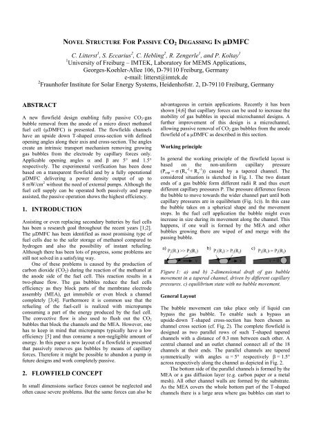
considered situation is sketched <strong>in</strong> Fig. 1. The two distant<br />
ends of a gas bubble <strong>for</strong>m different radii R and thus exert<br />
different capillary pressures P. The pressure difference <strong>for</strong>ces<br />
the bubble to move towards the wider channel part until both<br />
capillary pressures are <strong>in</strong> equilibrium (Fig. 1c)). In this case<br />
the bubble takes on a spherical shape and the movement<br />
stops. In the fuel cell application the bubble might even<br />
<strong>in</strong>crease <strong>in</strong> size dur<strong>in</strong>g its movement along the channel. This<br />
happens, if one wall is <strong>for</strong>med by the MEA and other<br />
bubbles grow<strong>in</strong>g there are wiped of and merge with the<br />
pass<strong>in</strong>g bubble.<br />
Figure 1: a) and b) 2-dimensional draft of gas bubble<br />
movement <strong>in</strong> a tapered channel, driven by different capillary<br />
pressures. c) equilibrium state with no bubble movement.<br />
General Layout<br />
The bubble movement can take place only if liquid can<br />
bypass the gas bubble. To enable such a bypass an<br />
upside-down T-shaped cross-section has been chosen as<br />
channel cross section (cf. Fig. 2). The complete flowfield is<br />
designed as two parallel rows of such T-shaped tapered<br />
channels with a distance of 0.3 mm between each other. A<br />
central channel and an outlet channel connect all of the 18<br />
channels at their ends. The parallel channels are tapered<br />
symmetrically with angles α = 5° respectively β = 1.5°<br />
across respectively along the channel as depicted <strong>in</strong> Fig. 2.<br />
The bottom side of the parallel channels is <strong>for</strong>med by the<br />
MEA or a gas diffusion layer (e.g. carbon paper or a metal<br />
mesh). All other channel walls are <strong>for</strong>med by the substrate.<br />
As the MEA covers the whole bottom part of the T-shaped<br />
channels there is a large area where gas bubbles can start to
grow. At the narrowest part of the channel a grow<strong>in</strong>g bubble<br />
soon gets <strong>in</strong>to contact with the upper wall of the channel.<br />
While the bubble size still <strong>in</strong>creases, it is <strong>for</strong>ced to de<strong>for</strong>m<br />
from its spherical shape <strong>in</strong>to a stretched oval shape as<br />
depicted <strong>in</strong> Fig. 1. Thus a pressure gradient is developed and<br />
the bubble moves towards the central channel. This motion<br />
cont<strong>in</strong>ues towards the central channel as already described<br />
above <strong>for</strong> tapered channels. Once the central channel is<br />
reached, the bubble takes on a shape that only fills the central<br />
channel due to the T-shaped design. This behavior has<br />
basically been avowed by the authors <strong>in</strong> [6] and is now<br />
enhanced by the use of a tapered middle channel to move the<br />
bubble to the f<strong>in</strong>al outlet.<br />
Figure 2: a) Draft of one side of the flowfield <strong>in</strong>dicat<strong>in</strong>g the<br />
supply and outlet channel as well as the T-shaped parallel<br />
channels with their <strong>in</strong>cl<strong>in</strong>ation angles α and β. b) Sketch of<br />
the channel dimensions of the test samples <strong>in</strong> mm (not to<br />
scale).<br />
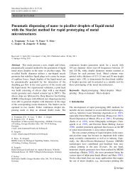
10 <strong>in</strong>lets back to wall boundary condition and ten new areas<br />
are selected and def<strong>in</strong>ed as <strong>in</strong>let. Afterwards the simulations<br />
are restarted with the <strong>in</strong>itial condition set to be the last result<br />
of the previous simulation sequence. This procedure is<br />
repeated several times as can be observed by the position of<br />
the small bubbles (dark gray) <strong>in</strong> Figure 3. The results show<br />
the anticipated bubble behaviour. The bubbles randomly<br />
grow <strong>in</strong> the channel and start to move towards the centre<br />
channel once they touch the upper channel wall or when<br />
wiped away by larger bubbles. When they arrive at the<br />
middle channel they start to move to the outlet.<br />
4. SAMPLE PREPARATION<br />
A negative of the structure with the dimensions given <strong>in</strong><br />
Fig. 2b) has been milled <strong>in</strong>to a brass plate to <strong>for</strong>m a hot<br />
emboss<strong>in</strong>g tool <strong>for</strong> the flowfield. To avoid the polymer to<br />
spill out sideways a frame <strong>for</strong> the master tool has been<br />
manufactured as well. Transparent PMMA (cf. Fig. 4) and a<br />
conductive graphite filled polymer (SGL BMA5) have been<br />
used as substrates <strong>for</strong> the hot emboss<strong>in</strong>g. After hot<br />
emboss<strong>in</strong>g of the substrates, mount<strong>in</strong>g holes and fluidic<br />
<strong>in</strong>terconnection holes were drilled.<br />
3. SIMULATION<br />
Prior to experimental verification the work<strong>in</strong>g pr<strong>in</strong>ciple has<br />
been validated by CFD simulations. CFD-ACE+ of<br />
ESI-Group (www.esi-cfd.com) has been used to model a part<br />
of the flowfield. Mak<strong>in</strong>g use of the channels symmetry to<br />
simplify the geometry the simulation time could be kept<br />
with<strong>in</strong> an acceptable timeframe of several days. A method<br />
has been developed to mimic the randomly distributed gas<br />
development at the fuel cells membrane as follows: Out of an<br />
array of 1000 small areas at the MEA side of the channel, ten<br />
areas are randomly chosen by an automatic script. They are<br />
switched from wall boundary condition to <strong>in</strong>let boundary<br />
with a def<strong>in</strong>ed mass flow rate. The mass flow rate of CO 2<br />
through each <strong>in</strong>let is based on the estimation that a typical<br />
current density of 100 mA cm -2 generates 0.26 ml m<strong>in</strong> -1 cm -2<br />
of CO 2 . Every 0.5 ms the simulation stops; the script sets the<br />
Figure 3: Simulation sequence with distributed bubble<br />
sources and bubble removal due to capillary <strong>for</strong>ces.<br />
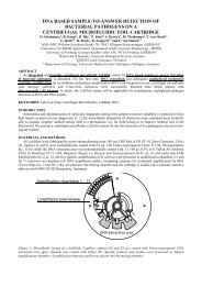
Figure 4: Photograph of one of the transparent test samples<br />
5. EXPERIMENTAL VERIFICATION<br />
Two different experiments were set up to study the<br />
functionality of the new flowfield design. Visual studies of<br />
the bubble behavior <strong>in</strong>side the flowfield have been<br />
per<strong>for</strong>med with the transparent samples while the graphite<br />
filled samples were used to build a functional µDMFC.<br />
Transparent test cell<br />
A mount<strong>in</strong>g frame, the transparent PMMA-sample with the<br />
flowfield, two sheets of metal mesh with a MEA <strong>in</strong> between<br />
and a lower mount<strong>in</strong>g frame <strong>for</strong>med the stack <strong>for</strong> the bubble<br />
development experiments. To avoid methanol leakage, the<br />
stack was sealed with silicone and tightly screwed together.<br />
The metal meshes were connected electrically and the system<br />
was primed with a 2 M methanol solution. By apply<strong>in</strong>g a<br />
current of 500 mA and a voltage of approximately 0.2 V the<br />
creation of gas bubbles has been <strong>for</strong>ced (cf. Fig. 5). To allow<br />
cont<strong>in</strong>uous passive fluid flow dur<strong>in</strong>g the experiments a fuel<br />
cartridge was connected to the supply channel. CO 2 could be<br />
released through the outlet channel at the upper right corner.<br />
First the bubbles moved towards the central channel. Once
there, they grew until they once aga<strong>in</strong> started to move. This<br />
time they moved towards the outlet channel as anticipated<br />
due to the simulation results.<br />
Short time test<strong>in</strong>g<br />
The considered flowfield was designed <strong>for</strong> totally passive as<br />
well as <strong>for</strong> pump assisted operation. Thus a direct<br />
comparison of experimental results <strong>in</strong> active and passive<br />
mode is possible. Fig. 7 shows the polarization plots and the<br />
power densities of short time measurements with a 4 M<br />
methanol solution. With decreas<strong>in</strong>g flowrate the efficiency of<br />
the fuel cell <strong>in</strong>creases as shown by the <strong>in</strong>creas<strong>in</strong>g power<br />
densities.<br />
Figure 5: Picture sequence of gas bubbles develop<strong>in</strong>g and<br />
their movement <strong>in</strong>side one test sample with a 2 M methanol<br />
solution.<br />
Fuel cell assembly<br />
To test the flowfield <strong>for</strong> fuel cell operation a planar fuel cell<br />
has been assembled (cf. Fig. 6). The cathode was made of an<br />
ord<strong>in</strong>ary pr<strong>in</strong>ted circuit board (PCB). The PCB is a lam<strong>in</strong>ate<br />
of a substrate - a composite material of glass fibre and<br />
epoxide – sandwiched between two copper layers of 35 µm<br />
thickness. In the cathode material parallel rectangular<br />
open<strong>in</strong>gs of 3 mm × 21 mm with a spac<strong>in</strong>g of 1 mm have<br />
been milled. This results <strong>in</strong> an electrochemical active area of<br />
21 mm × 43 mm. As current collector and outside electrical<br />
contact the copper layer of the PCB was used. The hot<br />
embossed anode consists of a graphite plate (SGL BMA5)<br />
with the flowfield structure described above impr<strong>in</strong>ted. As<br />
anode contact a copper plate was placed on top of the<br />
graphite plate. The MEA was sandwiched between two<br />
100 µm thick foils to avoid short circuits between the<br />
electrodes. This sandwich was glued to the anode.<br />
Nafion 117 with a PtRu/Pt load<strong>in</strong>g of 3.5 mg cm -2 and an<br />
ionomer thickness of 180 µm was used as the MEA. Toray<br />
carbon paper with a thickness of 350 µm was applied as<br />
diffusion layers between the plates and the MEA. The whole<br />
assembly was pressed together by six M3 screws with a<br />
torque of 0.5 Nm each. Adhesives at the edges which were<br />
pressed together while cur<strong>in</strong>g ensured sufficient contact<br />
pressure between the plates also <strong>for</strong> future operation.<br />
Figure 7: Short time measurements with a 4 M methanol<br />
solution at two pumped flow rates and a passive system<br />
setup.<br />
Together with the decreas<strong>in</strong>g flowrate the amount of<br />
available methanol <strong>for</strong> the chemical reaction decreases too.<br />
Hence the methanol concentration is lower. This yields a<br />
lower methanol crossover through the membrane and thus a<br />
better system per<strong>for</strong>mance. Furthermore additional effects<br />
appear if the pump is switched off completely. Comparable<br />
to the case of lower flowrates, the methanol concentration<br />
decreases over time as well as the methanol crossover. Due<br />
to this the efficiency also <strong>in</strong>creases. On the other hand there<br />
is another effect that is connected to the phase change of<br />
methanol which also ga<strong>in</strong>s <strong>in</strong>fluence. As the methanol is not<br />
flushed through the flowfield together with the gas bubbles<br />
more methanol enters the vapour phase. It is well known that<br />
this leads to better k<strong>in</strong>etics on the anode and a lower<br />
crossover through the membrane [7]. Due to this a low<br />
flowrate or even no flow is advantageous. But to operate the<br />
fuel cell without any flow would yield a power-breakdown<br />
after all methanol had been converted. To overcome this<br />
problem one possible solution is to pump fuel <strong>in</strong>to the system<br />
at certa<strong>in</strong> <strong>in</strong>tervals to refill the miss<strong>in</strong>g volume and to<br />
<strong>in</strong>crease the methanol concentration aga<strong>in</strong>. The benefit is<br />
twofold: The fuel cells efficiency is higher compared to a<br />
cont<strong>in</strong>uously pumped system and there is no cont<strong>in</strong>uous<br />
energy demand of the pump as it is deactivated most of the<br />
time.<br />
Figure 6: Draft of the fuel cell assembly (not to scale).
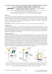
Long time measurements<br />
The assumption that the efficiency <strong>in</strong>creases by pump<strong>in</strong>g at<br />
<strong>in</strong>tervals has been tested <strong>in</strong> long time measurements with a<br />
4 M methanol solution. For the experiments three<br />
configurations have been chosen: Pump<strong>in</strong>g cont<strong>in</strong>uously,<br />
pump<strong>in</strong>g at <strong>in</strong>tervals (approximately 23 m<strong>in</strong> pause, 15 s<br />
pump<strong>in</strong>g) and an open cartridge without any pump. In the<br />
case of pump<strong>in</strong>g cont<strong>in</strong>uously a stable current density of<br />
about 14.5 mA cm -2 was reached (cf. Fig. 8). As expected the<br />
results of the other configurations showed a higher current<br />
density dur<strong>in</strong>g extended operation. It can be seen that over<br />
the time the per<strong>for</strong>mance <strong>for</strong> this two configurations<br />
<strong>in</strong>creases until the depletion of methanol leads to a decl<strong>in</strong>e of<br />
the current density. In the pump driven configuration the cell<br />
assembly runs <strong>for</strong> 23 m<strong>in</strong> and then new fuel is pumped <strong>in</strong>to<br />
the system <strong>for</strong> 15 s. Dur<strong>in</strong>g the time the pump is switched off,<br />
no flow of methanol takes place from the cartridge <strong>in</strong>to the<br />
cell. In the case of the open cartridge a small flow refuels the<br />
system cont<strong>in</strong>uously due to a small difference <strong>in</strong> hydrostatic<br />
height (about 10 mm) of cartridge and cell. This leads to an<br />
even better per<strong>for</strong>mance compared to the other<br />
configurations. But also <strong>for</strong> this setup the methanol depletes<br />
after a while. There<strong>for</strong>e the level of the cartridge was<br />
<strong>in</strong>creased <strong>for</strong> a few seconds after about 25 m<strong>in</strong> to flush new<br />
fuel <strong>in</strong>to the flowfield by hydrostatic pressure.<br />
Figure 8: Long time measurements with a 4 M methanol<br />
solution at 0.25 V. Cont<strong>in</strong>uously pumped (0.225 ml/m<strong>in</strong>),<br />
pump<strong>in</strong>g at <strong>in</strong>tervals (~23 m<strong>in</strong> pause; 15 s pump<strong>in</strong>g) and<br />
passive with refuel<strong>in</strong>g by hydrostatic pressure after ~25 m<strong>in</strong>.<br />
6. CONCLUSIONS AND OUTLOOK<br />
A passive removal of gas bubbles <strong>in</strong> a µDMFC has been<br />
proofed us<strong>in</strong>g tapered microchannels. The feasibility was<br />
demonstrated with a CFD-simulation and a prototype<br />
flowfield was manufactured by hot emboss<strong>in</strong>g techniques.<br />
With the aid of transparent test-samples the work<strong>in</strong>g<br />
pr<strong>in</strong>ciple of the structure has been demonstrated.<br />
Furthermore a complete µDMFC has been assembled. It<br />
exhibited a higher efficiency when operated passively<br />
compared to the situation when methanol was supplied<br />
cont<strong>in</strong>uously or at <strong>in</strong>tervals. Long term measurements lead to<br />
the conclusion that an open system that would be assisted by<br />
pump<strong>in</strong>g at <strong>in</strong>tervals could per<strong>for</strong>m best.<br />
Concern<strong>in</strong>g simulation, a connection of a 1-dimensional<br />
membrane model to the CFD-model is planned <strong>in</strong> the future.<br />
The 1-D-model locally determ<strong>in</strong>es the methanol reaction and<br />
thus also the local gas flow rate. This data can than be used<br />
as boundary condition which will lead to a more realistic<br />
simulation. On the experimental side further experiments<br />
have to be accomplished as the long term goal is a fuel cell<br />
system that allows <strong>for</strong> a cont<strong>in</strong>uously self susta<strong>in</strong>ed passive<br />
operation without us<strong>in</strong>g a pump.<br />
ACKNOWLEDGEMENTS<br />
This work was supported by the German Federal M<strong>in</strong>istry<br />
of Economics and Labour (BMWA) with<strong>in</strong> the VDI/VDE<br />
InnoNet-program PlanarFC.<br />
REFERENCES<br />
[1] C. K. Dyer, "Fuel cells <strong>for</strong> portable applications,"<br />
Journal of Power Sources, vol. 106, no. 1-2, pp. 31-34,<br />
Apr.2002.<br />
[2] A. He<strong>in</strong>zel, C. Hebl<strong>in</strong>g, M. Muller, M. Zedda, and C.<br />
Muller, "Fuel cells <strong>for</strong> low power applications," Journal<br />
of Power Sources, vol. 105, no. 2, pp. 250-255,<br />
Mar.2002.<br />
[3] P. Gravesen, J. Braneberg, and O. S. Jensen,<br />
"Microfluidics-a review," Journal of Micromechanics<br />
and Microeng<strong>in</strong>eer<strong>in</strong>g, vol. 3, no. 4, pp. 168-182,<br />
Dec.1993.<br />
[4] J. Kohnle, G. Waibel, R. Cernosa, M. Storz, H. Ernst, H.<br />
Sandmaier, T. Strobelt, and R. Zengerle, "A unique<br />
solution <strong>for</strong> prevent<strong>in</strong>g clogg<strong>in</strong>g of flow channels by gas<br />
bubbles," <strong>in</strong> Proc. of IEEE MEMS 2002, pp. 77-80.<br />
[5] D. J. Laser and J. G. Santiago, "A review of<br />
micropumps," Journal of Micromechanics and<br />
Microeng<strong>in</strong>eer<strong>in</strong>g, vol. 14, no. 6, p. R35-R64, June2004.<br />
[6] C. Litterst, J. Kohnle, H. Ernst, S. Messner, H.<br />
Sandmaier, R. Zengerle, and P. Koltay, "Mobility of Gas<br />
Bubbles <strong>in</strong> CHIC-type Flow Channels," <strong>in</strong> Proc.<br />
ACTUATOR 2004, pp. 541-544.<br />
[7] A. K. Shukla, P. A. Christensen, A. Hamnett, and M. P.<br />
Hogarth, "A Vapor-Feed Direct-Methanol Fuel-Cell<br />
with Proton-Exchange Membrane Electrolyte," Journal<br />
of Power Sources, vol. 55, no. 1, pp. 87-91, May1995.