Konrad Zuse's Legacy: The Architecture of the Z1 and Z3
Konrad Zuse's Legacy: The Architecture of the Z1 and Z3
Konrad Zuse's Legacy: The Architecture of the Z1 and Z3

Create successful ePaper yourself
Turn your PDF publications into a flip-book with our unique Google optimized e-Paper software.
--- -- -<br />
.' .., .-<br />
--:...~~~.. -<br />
<strong>Konrad</strong> <strong>Zuse's</strong> <strong>Legacy</strong>:<br />
<strong>The</strong> <strong>Architecture</strong> <strong>of</strong> <strong>the</strong> <strong>Z1</strong> <strong>and</strong> <strong>Z3</strong><br />
RAUL ROJAS<br />
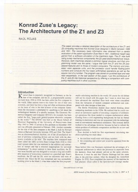
This paper provides a detai/ed description <strong>of</strong> <strong>the</strong> architecture <strong>of</strong> <strong>the</strong> ZI <strong>and</strong><br />
<strong>Z3</strong> computing machines that <strong>Konrad</strong> Zuse designed in Berlin between 1936<br />
<strong>and</strong> 1941. <strong>The</strong> necessary basic information was obtained from a careful<br />
evaluation <strong>of</strong> <strong>the</strong> patent application Zuse filed in 1941. Additional insight was<br />
gained from a s<strong>of</strong>tware simulation <strong>of</strong> <strong>the</strong> machine's logic. <strong>The</strong> ZI was bui/t<br />
using purely mechanical components; <strong>the</strong> <strong>Z3</strong> used electromechanical relays.<br />
However, both machines shared a common logical structure, <strong>and</strong> <strong>the</strong>ir programming<br />
model was <strong>the</strong> same. I argue that both <strong>the</strong> ZI <strong>and</strong> <strong>the</strong> <strong>Z3</strong> possessed<br />
features akin to those <strong>of</strong> modern computers: <strong>The</strong> memory <strong>and</strong> processor<br />
were separate units, <strong>and</strong> <strong>the</strong> processor could h<strong>and</strong>le fIoating7point<br />
numbers <strong>and</strong> compute <strong>the</strong> four basic arithmetical operations as weil as <strong>the</strong><br />
square root <strong>of</strong> a number. <strong>The</strong> program was stored on punched tape <strong>and</strong> was<br />
read sequentially. In <strong>the</strong> last section <strong>of</strong> this paper, I put <strong>the</strong> architecture <strong>of</strong><br />
<strong>the</strong> ZI <strong>and</strong> <strong>Z3</strong> into historical perspective by <strong>of</strong>fering a comparison with computing<br />
machines built in o<strong>the</strong>r countries.<br />
Introduction<br />
<strong>Konrad</strong> Zuse is popularly recognized in Germany as <strong>the</strong> fa<strong>the</strong>r<br />
<strong>of</strong> <strong>the</strong> computer, <strong>and</strong> his ZI, a programmable automaton<br />
built from 1936 to 1938, has been called <strong>the</strong> first computer in<br />
<strong>the</strong> world. O<strong>the</strong>r nations reserve this honor for one <strong>of</strong> <strong>the</strong>ir own<br />
scientists, <strong>and</strong> <strong>the</strong>re has been a long <strong>and</strong> <strong>of</strong>ten acrimonious debate<br />
on <strong>the</strong> issue <strong>of</strong> who is <strong>the</strong> true inventor <strong>of</strong> <strong>the</strong> computer. Sometimes<br />
<strong>the</strong> discussion is preempted by specifying in full detail <strong>the</strong><br />
technological features <strong>of</strong> a specific machine. <strong>The</strong> Electronic Numerical<br />
Integrator <strong>and</strong> Computer (ENIAC),for example, has been<br />
called <strong>the</strong> first "Iarge-scale general-purpose electronic computer<br />
in <strong>the</strong> world.,,2 <strong>The</strong> ENIAC was buiIt at <strong>the</strong> Moore School <strong>of</strong><br />
Electrical Engineering <strong>of</strong> <strong>the</strong> University <strong>of</strong> Pennsylvania from<br />
May 1943 to 1945. It solved its first problem in December 1945<br />
<strong>and</strong> was <strong>of</strong>ficially presented in February 1946. Ano<strong>the</strong>r contender<br />
for <strong>the</strong> tide <strong>of</strong> <strong>the</strong> first computer is <strong>the</strong> Mark I, built by Howard<br />
Aiken at Harvard University between 1939 <strong>and</strong> 1944.<strong>The</strong> Mark I<br />
was an electromechanieal machine, not <strong>of</strong> <strong>the</strong> all-mechanical nature<br />
<strong>of</strong> previous computing deviees <strong>and</strong> not bujlt with <strong>the</strong> electronies<br />
available at <strong>the</strong> time.1 <strong>The</strong> machine lohn Atanas<strong>of</strong>f built<br />
(later called <strong>the</strong> ABC) at Iowa'State College from 1938 to 1942<br />
used vacuum tubes but was restricted to <strong>the</strong> addition <strong>and</strong> subtraction<br />
<strong>of</strong> vectors <strong>and</strong> had a structure inappropriate for universal<br />
computation.2 In direct contrast to <strong>the</strong>se three machines, <strong>the</strong> ZI<br />
was more flexible <strong>and</strong> was designed to execute a lang <strong>and</strong> modifiable<br />
sequence <strong>of</strong> instructions contained on a punched tape. <strong>Zuse's</strong><br />
machines, <strong>the</strong> <strong>Z3</strong> <strong>and</strong> <strong>the</strong> Z4, were not electronic <strong>and</strong> were <strong>of</strong><br />
reduced size. Since <strong>the</strong> <strong>Z3</strong> was completed <strong>and</strong> was successfully<br />
working prior to <strong>the</strong> Mark I, it has been called <strong>the</strong> first programmahle<br />
calculating machine in <strong>the</strong> worId. Of course <strong>the</strong> old debate<br />
will not be closed with this paper, but I want to show here just<br />
how advanced <strong>the</strong> machines Zuse built were when considered<br />
from <strong>the</strong> viewpoint <strong>of</strong> modem computer architecrure <strong>and</strong> compared<br />
with o<strong>the</strong>r designs <strong>of</strong> that time.<br />
<strong>The</strong> Berlin Polytechnie srudent Zuse started thinking about<br />
computing machines in <strong>the</strong> 1930s. He reaIized that he could construct<br />
an automaton capable <strong>of</strong> executing a sequence <strong>of</strong> arithmetical<br />
operations Iike those needed to compute ma<strong>the</strong>matical tables.<br />
Coming from a civil engineering background. he had no formal<br />
training in electronics <strong>and</strong> was not acquainted with <strong>the</strong> technology<br />
used in conventional mechanical caIculators. This nominal deficit<br />
worked to his advantage, however, because he had to rethink <strong>the</strong><br />
whole problem <strong>of</strong> arithmetic computation <strong>and</strong> thus hit on new <strong>and</strong><br />
original solutions.<br />
Zuse decided to buiId his first experimental caIculating machine<br />
exploiting two main ideas:<br />
. <strong>the</strong> machine would work with binary numbers<br />
. <strong>the</strong> computing <strong>and</strong> control unit would be separated from <strong>the</strong><br />
storage.<br />
Years before lohn von Neumann explained <strong>the</strong> advantages <strong>of</strong> a<br />
computer architecture in which <strong>the</strong> processor is separated from<br />
<strong>the</strong> memory, Zuse had already anived at <strong>the</strong> same solution.<br />
However, it must be said that Charles Babbage had <strong>the</strong> same<br />
idea in <strong>the</strong> previous century when he designed his Analytical<br />
Engine. In 1936, Zuse completed <strong>the</strong> memory <strong>of</strong> <strong>the</strong> machine he<br />
had planned. (Zuse called it <strong>the</strong> Speicherwerk (storage mecha-<br />
1058-6 180197/S 10.00 e 1997 IEEE<br />
IEEE Annals <strong>of</strong><strong>the</strong> History <strong>of</strong>Computing, Vol. 19, No. 2, 1997 . 5
- --<br />
---<br />
<strong>the</strong> <strong>Z3</strong><br />
omputworked<br />
) adopt<br />
onds to<br />
rhe <strong>Z3</strong>.<br />
sor <strong>and</strong><br />
able <strong>of</strong><br />
procesmetical<br />
~ expon.<br />
<strong>The</strong><br />
ach in-<br />
proces-<br />
"ncbro<strong>of</strong><br />
each<br />
ll1e 1/0<br />
unit. '-<br />
'a!<br />
,d<br />
8;a!<br />
y<br />
.tabus<br />
ZJ. <strong>The</strong><br />
llowing<br />
Üfic<strong>and</strong><br />
bits <strong>of</strong><br />
oted by<br />
: <strong>of</strong> <strong>the</strong><br />
ment is<br />
ble valored<br />
in<br />
11point<br />
vention<br />
;it does<br />
;.2). so<br />
unit is<br />
equivalent to a signific<strong>and</strong> <strong>of</strong> 15 bits. However. <strong>the</strong>re is a problem<br />
with <strong>the</strong> number zero, which cannot be expressed using a normalized<br />
signific<strong>and</strong>. <strong>The</strong> <strong>Z3</strong> uses <strong>the</strong> convention that any signific<strong>and</strong><br />
with exponent -64 is to be considered equal to zero. Any<br />
number with exponent 63 is considered infinitely large. Operations<br />
involving zero <strong>and</strong> intinity are treated as exceptions. <strong>and</strong><br />
special hardware monitors <strong>the</strong> numbers loaded in <strong>the</strong> processor in<br />
order to set <strong>the</strong> exception flags (see below). With this convention3<br />
<strong>the</strong> smallest number -19 representable in <strong>the</strong> memory 62 <strong>of</strong> <strong>the</strong> <strong>Z3</strong>18<br />
is 2-6<br />
= 1.08 x 10 .<strong>and</strong> <strong>the</strong> largest is 1.999 x 2 =9.2 x 10 . <strong>The</strong><br />
arguments for computations can be entered as decimal numbers<br />
on <strong>the</strong> keyboard <strong>of</strong> <strong>the</strong> <strong>Z3</strong> (four digits). <strong>The</strong> exponent <strong>of</strong> <strong>the</strong><br />
decimal representation is entered by pushing <strong>the</strong> appropriate button<br />
in a row <strong>of</strong> buttons labeled -8, -7, 7. 8. <strong>The</strong> oririnal <strong>Z3</strong><br />
could accept input only between 1 x 10⁻⁸<strong>and</strong> 9.999 x 10 . <strong>Zuse's</strong><br />
reconstruction <strong>of</strong> <strong>the</strong> <strong>Z3</strong> for <strong>the</strong> Deutsches Museum in Munich<br />
provides enough buttons for larger exponents. With this arrangement.<br />
<strong>the</strong> whole numerical capacity <strong>of</strong> <strong>the</strong> machine can be reflected<br />
on <strong>the</strong> acceptable input. <strong>The</strong> same can be said <strong>of</strong> <strong>the</strong> output.<br />
However. <strong>the</strong> <strong>Z3</strong> does not print <strong>the</strong> numerical results <strong>the</strong> program<br />
produces. A single number is displayed on an array <strong>of</strong> lamps<br />
representing <strong>the</strong> digits from zero to nine. <strong>The</strong> largest number that<br />
can be displayed is 19.999. <strong>The</strong> smallest is 00001. <strong>The</strong> largest<br />
exponent that can be displayed is +8. <strong>the</strong> smallest -8.<br />
sign<br />
exponent<br />
. .<br />
signific<strong>and</strong><br />
~ 7 bits ; 14bits<br />
Fig. 2. <strong>The</strong> floating-point representation in memory.<br />
b_14<br />
Instruction Set<br />
<strong>The</strong> program for <strong>the</strong> <strong>Z3</strong> is stored on punched tape. One instruction<br />
is coded using eight bits for each row <strong>of</strong> <strong>the</strong> tape. <strong>The</strong> instruction<br />
set <strong>of</strong> <strong>the</strong> <strong>Z3</strong> consists <strong>of</strong> <strong>the</strong> nine instructions shown in Table 1.<br />
<strong>The</strong>re are three types <strong>of</strong> instructions: 1/0, memory. <strong>and</strong> arithmetical<br />
operators. <strong>The</strong> opcode has a variable length <strong>of</strong> two or five bits.<br />
Memory operations encode <strong>the</strong> address <strong>of</strong> a word in <strong>the</strong> lower six<br />
bits; that iso <strong>the</strong> addressing space has a maximum size <strong>of</strong> 64<br />
words. as mentioned above.<br />
<strong>The</strong> instructions on <strong>the</strong> punched tape can be arranged in any<br />
order. <strong>The</strong> instructions Lu <strong>and</strong> Ld (read from keyboard <strong>and</strong> display<br />
result. respectively) halt <strong>the</strong> machine. so that <strong>the</strong> operator has<br />
enough time to input a number or write down a result. <strong>The</strong> machine<br />
is <strong>the</strong>n restarted <strong>and</strong> continues processing <strong>the</strong> program.<br />
<strong>The</strong> instruction most conspicuously absent from <strong>the</strong> instruction<br />
set <strong>of</strong> <strong>the</strong> <strong>Z3</strong> is conditional branch;ng. Loops can be implemented<br />
by <strong>the</strong> simple expedient <strong>of</strong> bringing toge<strong>the</strong>r <strong>the</strong> two ends <strong>of</strong> <strong>the</strong><br />
punched tape. but <strong>the</strong>re is no way to implement conditional sequences<br />
<strong>of</strong> instructions. <strong>The</strong> <strong>Z3</strong> is <strong>the</strong>refore not a universal computer<br />
in <strong>the</strong> sense <strong>of</strong> Turing.<br />
Number <strong>of</strong> Cycles<br />
<strong>The</strong> <strong>Z3</strong> is a clocked machine. Each cycle is divided into five<br />
stages called I. II. III. IV, <strong>and</strong> V. <strong>The</strong> instruction in <strong>the</strong> punched<br />
tape is decoded in Stage I <strong>of</strong> a cycle. <strong>The</strong> two basic arithmetical<br />
operations <strong>of</strong> <strong>the</strong> machine are addition <strong>and</strong> subtraction <strong>of</strong> exponents<br />
<strong>and</strong> signific<strong>and</strong>s. <strong>The</strong> operations can be executed in <strong>the</strong> first<br />
tbree stages <strong>of</strong> each cycle. Stages IV <strong>and</strong> V are used to prepare<br />
arguments for <strong>the</strong> next operation or to write back results.<br />
TABlE 1<br />
INSTRUCTION SET AND OPCODES OF THE <strong>Z3</strong><br />
Type Instruction Description Opcode<br />
1/0 Lu read keyboard 01 110000<br />
Ld display result 01 111000<br />
memory Prz load address z 11 Z6ZSZ4<strong>Z3</strong>Z2<strong>Z1</strong><br />
Ps z store address z 10 Z6ZSZ4<strong>Z3</strong>Z2<strong>Z1</strong><br />
arithmetic Lm multiplication 01 001000<br />
Li division 01 010000<br />
Lw square root 01 011000<br />
LS1 addition 01 100000<br />
LS2 subtraction 01 101000<br />
<strong>The</strong> instructions implemented in <strong>the</strong> <strong>Z3</strong> require <strong>the</strong> foIlowing<br />
number <strong>of</strong> cycles:<br />
Multiplication:<br />
Division:<br />
Square roD!:<br />
Addition:<br />
Subtraction:<br />
Read keyboard:<br />
Display output:<br />
Load from memory:<br />
Store 10 memory:<br />
16 cycles<br />
18 cycles<br />
20 cycles<br />
3 cycles<br />
4 or 5 cycles. depending on <strong>the</strong> result<br />
9 1041 cycles. depending on <strong>the</strong> exponent<br />
9 1041 cycles. depending on <strong>the</strong> exponent<br />
I cycle<br />
o or 1cycle<br />
According to Zuse. <strong>the</strong> time required for a multiplication was<br />
three seconds. Considering that a multiplication operation needs<br />
16 cycles. one can estimate that <strong>the</strong> operating frequency <strong>of</strong> <strong>the</strong><br />
<strong>Z3</strong> was 16/3 ==5.33 Hz. It is a curious coincidence that <strong>the</strong> gatelevel<br />
simulation <strong>of</strong> <strong>the</strong> <strong>Z3</strong> that my students implememed using a<br />
personal computer also required around three seconds for a<br />
multiplication.<br />
<strong>The</strong> instruction most conspicuously<br />
absent from <strong>the</strong> instruction set <strong>of</strong> <strong>the</strong><br />
<strong>Z3</strong> is conditional branching.<br />
<strong>The</strong> number <strong>of</strong> cycles needed for <strong>the</strong> read <strong>and</strong> display instructions<br />
is variable. because it depends on <strong>the</strong> exponent <strong>of</strong> <strong>the</strong> arguments.Since<br />
<strong>the</strong> input has to be converted from decimal to binary<br />
representation. <strong>the</strong> number <strong>of</strong> multiplications needed with <strong>the</strong><br />
factor 10 or 0.1 is dictated by <strong>the</strong> decimal exponent (see below).<br />
Addition <strong>and</strong> subtraction require more than one cycle because.<br />
in <strong>the</strong> case <strong>of</strong> floating-point numbers. care has to be taken to set<br />
<strong>the</strong> size <strong>of</strong> <strong>the</strong> exponent <strong>of</strong> both arguments to <strong>the</strong> same value. This<br />
requires some extra comparisons <strong>and</strong> shifting.<br />
A number can be stored in memory in zero cycles when <strong>the</strong> result<br />
<strong>of</strong> <strong>the</strong> last arithmetical operation can be redirected to <strong>the</strong> desired<br />
memory address. In this case. <strong>the</strong> cycle needed for <strong>the</strong> store<br />
instruction overlaps <strong>the</strong> last cycle <strong>of</strong> <strong>the</strong> arithmetical operation.<br />
IEEE Annals <strong>of</strong><strong>the</strong> History <strong>of</strong>Computing. Vol. 19. No. 2. 1997 · 7
--<br />
~~~--==-<br />
01' is reset<br />
rted.<br />
e 23 <strong>and</strong><br />
;ain issue<br />
available<br />
Ollunit <strong>of</strong><br />
perations<br />
'jght side<br />
cers used<br />
programjster<br />
pair<br />
<strong>and</strong> sigt<br />
<strong>and</strong> <strong>the</strong><br />
visible to<br />
A <strong>and</strong> T"'I<br />
'. resp,-_<br />
, put into<br />
. put into<br />
gistel' in-<br />
NS selec-<br />
'peration.<br />
Jen Be is<br />
::::J<br />
J;;nific<strong>and</strong>s<br />
:. Fd, <strong>and</strong><br />
'ntents <strong>of</strong><br />
e box <strong>of</strong><br />
1 be seen<br />
a 01' Ab.<br />
.a. Ab, 01'<br />
Jf Part B<br />
<strong>the</strong> mulbetween<br />
Bf <strong>and</strong> Ba <strong>and</strong> a shifter between Bf <strong>and</strong> Bb. <strong>The</strong> first shifter can<br />
displace <strong>the</strong> signific<strong>and</strong> up to two positions to <strong>the</strong> right <strong>and</strong> one<br />
position to "<strong>the</strong>left. This amounts to a division <strong>of</strong> Bf by foul' 01'a<br />
mu!tiplication with <strong>the</strong> constant two. <strong>The</strong> second shifter can disp!ace<br />
<strong>the</strong> signific<strong>and</strong> in Af from one to 16 positions to <strong>the</strong> right<br />
<strong>and</strong> from one to 15 positions to <strong>the</strong> left. <strong>The</strong>se shifts are needed<br />
for addition <strong>and</strong> subtraction <strong>of</strong> floating-point numbers. Multiplication<br />
<strong>and</strong> division with powers <strong>of</strong> two can <strong>the</strong>refore be performed<br />
when <strong>the</strong> oper<strong>and</strong>s for <strong>the</strong> next arithmetical operation are<br />
fetched <strong>and</strong>, in this sense, do not consume time.<br />
<strong>The</strong> number <strong>of</strong> bits used in <strong>the</strong> registers is as foliows:<br />
Af<br />
Aa<br />
Ab<br />
Ae<br />
7 bits<br />
8<br />
8<br />
8<br />
Bf<br />
Ba<br />
Bb<br />
Be<br />
17bits<br />
19<br />
18<br />
18<br />
As can be seen from this list. Ae uses one extra bit to h<strong>and</strong>le <strong>the</strong><br />
addition <strong>of</strong> <strong>the</strong> exponents <strong>of</strong> <strong>the</strong> arguments. Part B <strong>of</strong> <strong>the</strong> proces-<br />
SOl'uses two extra bits for <strong>the</strong> signific<strong>and</strong>s (b_15<strong>and</strong> b_16)<strong>and</strong><br />
makes explicit bo, which is not stored in memory.<strong>The</strong> extra bits at<br />
positions -15 <strong>and</strong> -16 are included to increase <strong>the</strong> precision <strong>of</strong> <strong>the</strong><br />
computations. <strong>The</strong>refore. <strong>the</strong> total number <strong>of</strong> bits needed to store<br />
<strong>the</strong> result <strong>of</strong> an arithmetical operation in Bf is 17 bits. Registers<br />
Ba <strong>and</strong> Bb require more extra bits (ba~.bai' <strong>and</strong> bbl) to h<strong>and</strong>le<br />
intermediate results <strong>of</strong> some <strong>of</strong> <strong>the</strong> numerical algorithms. In particular.<br />
<strong>the</strong> square root algorithm can lead to partial computations<br />
in Ba requiring three bits to <strong>the</strong> left <strong>of</strong> <strong>the</strong> decimal point.<br />
<strong>The</strong> basic primitive operation <strong>of</strong> <strong>the</strong> data path is <strong>the</strong> addition 01'<br />
subtraction 01'exponents 01'signific<strong>and</strong>s. When <strong>the</strong> relay As 01'Bs<br />
is set, <strong>the</strong> negation <strong>of</strong> <strong>the</strong> second argument (Ab 01'Bb) is fed into<br />
<strong>the</strong> ALU. <strong>The</strong>refore, if <strong>the</strong> relay As is set to one. <strong>the</strong> ALU in Part<br />
A subtracts its arguments. o<strong>the</strong>rwise <strong>the</strong>y are added. <strong>The</strong> same is<br />
true for Part B<strong>and</strong> <strong>the</strong> relay Bs. <strong>The</strong> constant 01'one is needed to<br />
build <strong>the</strong> two's complement<strong>of</strong> a number.<br />
Assurne that two numbers with <strong>the</strong> same exponent are to be<br />
added. <strong>The</strong> first exponent is stored in Af. <strong>the</strong> second in Ab.<br />
Since <strong>the</strong>y are equal, no operation has to be performed on this<br />
side <strong>of</strong> <strong>the</strong> machine. In Part B, <strong>the</strong> signific<strong>and</strong> <strong>of</strong> <strong>the</strong> first numbel'<br />
is stored in Bf <strong>and</strong> <strong>the</strong> signific<strong>and</strong> <strong>of</strong> <strong>the</strong> second in Bb. <strong>The</strong><br />
first step consists <strong>of</strong> loading Ba with Bf by setting <strong>the</strong> relay box<br />
Fa to one. <strong>The</strong> addition is performed next. <strong>the</strong> relay Bt is set to<br />
one, <strong>and</strong> so <strong>the</strong> result Ba + Bb is assigned to Be. <strong>The</strong> relay box<br />
Ff is now set to one. <strong>and</strong> <strong>the</strong> result is stored in Bf. As one can<br />
see. <strong>the</strong> information can move between registers <strong>and</strong> so flow<br />
through <strong>the</strong> data path. <strong>The</strong> computer architect has to provide <strong>the</strong><br />
correct sequence <strong>of</strong> activations <strong>of</strong> <strong>the</strong> relay boxes in order to get<br />
<strong>the</strong> desired operation. This is done in <strong>the</strong> 23 using a technique<br />
very similar to microprogrammirtg.<br />
<strong>The</strong> Control Unit<br />
Fig. 4 shows a more detailed diagram <strong>of</strong> <strong>the</strong> control unit <strong>and</strong> <strong>of</strong><br />
<strong>the</strong> 1/0 panels. <strong>The</strong> circuit Pa decodes <strong>the</strong> opcode 01'<strong>the</strong> instruction<br />
read from <strong>the</strong> punched tape. If it is a memory instruction.<br />
circuit Pb sets <strong>the</strong> address bus to <strong>the</strong> value <strong>of</strong> <strong>the</strong> lower six bits <strong>of</strong><br />
<strong>the</strong> opcode. <strong>The</strong> contro! unit determines <strong>the</strong> correct microsequencing<br />
<strong>of</strong> <strong>the</strong> instructions.<strong>The</strong>re are special circuits for each <strong>of</strong><br />
<strong>the</strong> operations in <strong>the</strong> instruction set.<br />
Circuit 2 represents <strong>the</strong> panel <strong>of</strong> buttons used to enter a decimal<br />
number in <strong>the</strong> machine. Only one button in each <strong>of</strong> <strong>the</strong> foul'<br />
columns can be activated. <strong>The</strong> exponent is set by pressing one <strong>of</strong><br />
<strong>the</strong> buttons labeled -8 to 8 in circuit K. <strong>The</strong> output display is very<br />
similar to <strong>the</strong> input panel. but here !amps iIluminate <strong>the</strong> appropriate<br />
decimal digits, <strong>the</strong> exponent <strong>of</strong> <strong>the</strong> number (circuit Q), as weil<br />
as its sign. Note that <strong>the</strong>re is a fifth digit for <strong>the</strong> output (which can<br />
be only one 01'zero).<br />
PU"""""""<br />
Fig. 4. <strong>The</strong> control<br />
control uni!<br />
..'"<br />
U<br />
dis lav D<br />
multllic:auon M<br />
divISion 1<br />
suateCOOI W<br />
3dd1sub S<br />
Sl~n V<br />
unit <strong>and</strong> 110 panels.<br />
exponent <strong>of</strong> input<br />
databus<br />
data b...<br />
Once a decimal number has been set, a data bus transmits <strong>the</strong><br />
digits to register Ba. <strong>and</strong> a complex series <strong>of</strong> operations is started.<br />
<strong>The</strong> decimal input must be transformed into a binary number.This<br />
requires a chain <strong>of</strong> multiplications. which is longer according to<br />
<strong>the</strong> absolute magnitude <strong>of</strong> <strong>the</strong> exponent. If <strong>the</strong> exponent is zero,<br />
<strong>the</strong> whole transformation requires nine cycles. but if it is -8, <strong>the</strong><br />
operation requires 9 + 4 x 8 =41 cycles.<br />
<strong>The</strong>re are a lot <strong>of</strong> details that <strong>the</strong><br />
engineer designing <strong>the</strong> "microprogram"<br />
must keep in mind, o<strong>the</strong>rwise short<br />
circuits can destroy <strong>the</strong> hardware.<br />
Microcontrol <strong>of</strong> <strong>the</strong> <strong>Z3</strong><br />
<strong>The</strong> heart <strong>of</strong> <strong>the</strong> control unit is made up <strong>of</strong> its microsequencers.<br />
Before I describe <strong>the</strong> way <strong>the</strong>y work, it is necessary to take a<br />
closer look at <strong>the</strong> chaining <strong>of</strong> arithmetical instructions in <strong>the</strong> 23.<br />
Fig. 5 shows <strong>the</strong> main idea. Each cycle <strong>of</strong> <strong>the</strong> 23 is divided into<br />
five stages. Stages IV <strong>and</strong> V are used to move information around<br />
in <strong>the</strong> machine. During Stages I, 11, <strong>and</strong> III, an additionlsubtraction<br />
is computed in Part A <strong>and</strong> ano<strong>the</strong>r in Part B <strong>of</strong> <strong>the</strong><br />
23. I call this <strong>the</strong> "execute" phase <strong>of</strong> an instruction. A typical<br />
instruction fetches its arguments. executes. <strong>and</strong> writes back <strong>the</strong><br />
result. 2use tOokgreat care to save execution time by overlapping<br />
<strong>the</strong> fetch stage <strong>of</strong> <strong>the</strong> next instruction with <strong>the</strong> write-back stage <strong>of</strong><br />
<strong>the</strong> current one. One can think <strong>of</strong> an execution cycle as consisting<br />
<strong>of</strong> just two stages, as shown in Fig. 5, where <strong>the</strong> first two cycles<br />
<strong>of</strong> aseries <strong>of</strong> instructions have been labeled. I have adopted this<br />
convention in <strong>the</strong> tabulaI' diagrams <strong>of</strong> <strong>the</strong> numerical algorithms<br />
discussed later in this article.<br />
<strong>The</strong> microsequencing is done by special contro! wheels. <strong>The</strong>re<br />
is one for <strong>the</strong> mu!tiplicationalgorithm. ano<strong>the</strong>r to control division,<br />
<strong>and</strong> yet ano<strong>the</strong>r for <strong>the</strong> square root instruction. <strong>The</strong> moving arm<br />
shown in Fig. 6 starts moving clockwise as soon as <strong>the</strong> control<br />
IEEE Anna/s <strong>of</strong><strong>the</strong> History <strong>of</strong>Computing, Vol. 19. No. 2,1997 · 9
Jst for <strong>the</strong><br />
. are much<br />
I in Stages<br />
1 by cornigit<br />
one at<br />
~fer to <strong>the</strong><br />
ems more<br />
o<strong>the</strong>r regle<br />
bitwise<br />
'nd partial<br />
.sters, i.e.,<br />
>at which<br />
nputed by<br />
:n a bit is<br />
[he line is<br />
:ircuit can<br />
-16are <strong>the</strong><br />
[he corre-<br />
XOR bCi'<br />
carries up<br />
activ.<br />
: bit pOS!-<br />
'§"<br />
bc.16<br />
16<br />
ns <strong>the</strong> 23<br />
nonnally<br />
4' bd_16<br />
~<br />
~RI<br />
be.16-<br />
1Iconven-<br />
<strong>Z3</strong> solves<br />
.v <strong>and</strong> unany<br />
arith-<br />
'cuit looks<br />
IYnumber<br />
Nn, is set<br />
to one if <strong>the</strong> number is stored in <strong>the</strong> register pair . If <strong>the</strong><br />
number is stored in <strong>the</strong> register pair , <strong>the</strong> relay Nn2is set<br />
10one. In this way. we always know if one or both <strong>of</strong> <strong>the</strong> arguments<br />
for an arithmetical operation are zero. Something similar is<br />
done for any exponent <strong>of</strong> value 63 (an infinite number, according<br />
to <strong>the</strong> convenlion). In this case, <strong>the</strong> relays Ni, or Niz are set to<br />
one. according to <strong>the</strong> register pair in which <strong>the</strong> number is stored.<br />
Operations involving "exceptional" numbers (zero or infinity)<br />
are perfonned as usual, but <strong>the</strong> result is overridden by <strong>the</strong> snooping<br />
circuit. Assurne, for example, that a multiplication is computed<br />
<strong>and</strong> that <strong>the</strong> first argument is zero (Nn, is set to one). <strong>The</strong><br />
compulation proceeds as usual, but in each cycle <strong>the</strong> snooping<br />
circuil produces <strong>the</strong> result -64 at <strong>the</strong> output <strong>of</strong> <strong>the</strong> adder <strong>of</strong> Part A.<br />
It does not matter what operations are perfonned with <strong>the</strong> signific<strong>and</strong>s<br />
because <strong>the</strong> exponent <strong>of</strong> <strong>the</strong> result is set to -64, <strong>and</strong> <strong>the</strong>refore<br />
<strong>the</strong> final result is zero. Division by an infinite number can be<br />
h<strong>and</strong>led in a similar manner. <strong>The</strong> <strong>Z3</strong> can detect undefined operationssuchas<br />
0 / 0, 00 - 00, 00 / 00, <strong>and</strong>0 x 00. In all<strong>the</strong>secases,<strong>the</strong><br />
corresponding exception lamp lights on <strong>the</strong> output panel, <strong>and</strong> <strong>the</strong><br />
machine is stopped. <strong>The</strong> 23 always produces <strong>the</strong> correct result<br />
when one <strong>of</strong> <strong>the</strong> arguments is zero or 00 <strong>and</strong> <strong>the</strong> o<strong>the</strong>r is a number<br />
within bounds. This was not <strong>the</strong> case for <strong>the</strong> Zl. Zuse thought <strong>of</strong>,<br />
but did not implement, exception h<strong>and</strong>ling in <strong>the</strong> 21. <strong>The</strong> machine<br />
could not correctly perfonn some computations involving zero.16<br />
An additional circuit looks at <strong>the</strong> exponent <strong>of</strong> <strong>the</strong> result at <strong>the</strong><br />
output <strong>of</strong> <strong>the</strong> exponent's adder. If <strong>the</strong> exponent is greater than or<br />
equal to 63, overflow has occurred <strong>and</strong> <strong>the</strong> result must be set to 00.<br />
If <strong>the</strong> exponent is lower than -64, underflow has occurred <strong>and</strong> <strong>the</strong><br />
result must be set to zero. To do this, <strong>the</strong> appropriate relay (Nnl or<br />
Ni,) is set to one.<br />
Zuse managed to implement exception h<strong>and</strong>ling using just a few<br />
relays. This feature <strong>of</strong> <strong>the</strong> <strong>Z3</strong> is one <strong>of</strong> <strong>the</strong> most elegant in <strong>the</strong> whole<br />
design. Many <strong>of</strong> <strong>the</strong> early microprocessors <strong>of</strong> <strong>the</strong> 1970s did not<br />
include exception h<strong>and</strong>ling <strong>and</strong> left it to <strong>the</strong> s<strong>of</strong>tWare. <strong>Zuse's</strong> approach<br />
is sounder, since it frees programmers from <strong>the</strong> tedium <strong>of</strong><br />
checking <strong>the</strong> bounds <strong>of</strong> <strong>the</strong>ir numbers before each operation.<br />
Addition <strong>and</strong> Subtraction<br />
In order to add or subtract two floating-point numbers x <strong>and</strong> y,<br />
<strong>the</strong>ir representation must be reduced to <strong>the</strong> same exponent. After<br />
Ihis has been done, only <strong>the</strong> signific<strong>and</strong>s have to be added or subtracted.<br />
If <strong>the</strong> exponents are different, <strong>the</strong> signific<strong>and</strong> <strong>of</strong> <strong>the</strong><br />
smaller number is shifted to <strong>the</strong> right as many places as necessary<br />
(<strong>and</strong> its exponent is incremented correspondingly to keep <strong>the</strong><br />
number unchanged) until both exponents are equal. It can, <strong>of</strong><br />
course, happen that <strong>the</strong> smaller number becomes zero after 17<br />
shifts to <strong>the</strong> right. .<br />
<strong>The</strong> signs <strong>of</strong> <strong>the</strong> two numbers are compared before deciding on<br />
<strong>the</strong> type <strong>of</strong> operation to be executed. If an addition has been requested<br />
<strong>and</strong> <strong>the</strong> signs are <strong>the</strong> same, <strong>the</strong> addition is perfonned. If<br />
<strong>the</strong> signs are different, a subtraction is executed. If a subtraction<br />
has been requested <strong>and</strong> <strong>the</strong> signs are different, an addition is executed.<br />
If <strong>the</strong> signs are <strong>the</strong> same, <strong>the</strong> subtraction is executed. A<br />
special circuit sets <strong>the</strong> sign <strong>of</strong> <strong>the</strong> final result according to <strong>the</strong><br />
signs <strong>of</strong> <strong>the</strong> arguments <strong>and</strong> <strong>the</strong> sign <strong>of</strong> <strong>the</strong> partial result.<br />
Addition <strong>and</strong> subtraction are controlled by a chain <strong>of</strong> relays<br />
(nol by a control wheel), since <strong>the</strong> maximum number <strong>of</strong> cycles<br />
needed is low. Fig. 8 shows <strong>the</strong> synchronization required for <strong>the</strong><br />
addition <strong>of</strong> two numbers. Initially, <strong>the</strong> arguments for <strong>the</strong> addition<br />
are stored in <strong>the</strong> register pairs <strong>and</strong> . In <strong>the</strong> first<br />
cycle, <strong>the</strong> exponents are sublracted. In Cycle 2, <strong>the</strong> signific<strong>and</strong><br />
with <strong>the</strong> larger exponent is loaded into register Ba, <strong>and</strong> <strong>the</strong> signific<strong>and</strong><br />
with <strong>the</strong> smaller exponent is loaded into register Bb. <strong>The</strong><br />
signific<strong>and</strong> in register Bb is shifted as many places to <strong>the</strong> right as<br />
<strong>the</strong> absolute value <strong>of</strong> <strong>the</strong> difference <strong>of</strong> <strong>the</strong> exponents (exception<br />
h<strong>and</strong>ling takes care <strong>of</strong> <strong>the</strong> case in which <strong>the</strong> smaller number becomes<br />
zero after Ihe shift). In Stages I, H, <strong>and</strong> ur <strong>of</strong> Cycle 2, <strong>the</strong><br />
signific<strong>and</strong>s are added, <strong>and</strong> finally <strong>the</strong> processor tests if <strong>the</strong> result<br />
is greater than two. If this is <strong>the</strong> case, <strong>the</strong> signific<strong>and</strong> is shifted<br />
one position to <strong>the</strong> right <strong>and</strong> <strong>the</strong> exponenl is incremented by one.<br />
Note that <strong>the</strong> test "if (Be 2:2)" in Part A <strong>of</strong> <strong>the</strong> arithmetical unit is<br />
done after Be has already been computed in Part B during Stages<br />
I, H, <strong>and</strong> ur <strong>of</strong> Cycle 2.<br />
Zuse managed to implement exception<br />
h<strong>and</strong>ling using just a few relays. This<br />
feature <strong>of</strong> <strong>the</strong> <strong>Z3</strong> is one <strong>of</strong> <strong>the</strong> most<br />
elegant in <strong>the</strong> whole design.<br />
In <strong>the</strong> case <strong>of</strong> a subtraction, four or five cycles are needed. Fig.<br />
9 shows <strong>the</strong> synchronizalion required for a sublraction. <strong>The</strong> first<br />
two cycles are almost identical to <strong>the</strong> first tWocycles <strong>of</strong> <strong>the</strong> addition<br />
algorithm, but now <strong>the</strong> signific<strong>and</strong>s are subtracted. Cycle 3 is<br />
executed only when <strong>the</strong> difference <strong>of</strong> <strong>the</strong> signific<strong>and</strong>s is negative.<br />
<strong>The</strong> effect <strong>of</strong> Cycle 3 is just to make <strong>the</strong> signific<strong>and</strong> <strong>of</strong> <strong>the</strong> result<br />
positive. Cycle 4 is very importam: <strong>The</strong> difference <strong>of</strong> two normalized<br />
signific<strong>and</strong>s can have many zeros in <strong>the</strong> first bit positions<br />
to <strong>the</strong> left. <strong>The</strong> result is nonnalized by shifting Be to <strong>the</strong> left as<br />
many places as necessary (this is done with <strong>the</strong> shifter between<br />
<strong>the</strong> relay box Fd <strong>and</strong> register Bb). <strong>The</strong> number <strong>of</strong> one-bit shifts is<br />
subtracted from <strong>the</strong> exponent in Part A <strong>of</strong> <strong>the</strong> processor. In Cycle<br />
5, <strong>the</strong> result is stored in <strong>the</strong> register pair .<br />
Hcycle I stage I exponent t' sigmnc<strong>and</strong> -""..---- "<br />
0 1,l.III<br />
1 IV.V Aa:=Af<br />
2 IV,V<br />
1.!I.lI! Ae:=Aa-Ab Be:=O+8b<br />
1.!I,lI!<br />
ie (Ae2:;O)<strong>the</strong>n Ab:=O, Aa,;:Af<br />
jf (Ae2:0) tbcn Ba.:=Bf. Bb:=Be (shifted)<br />
eise Aa:=O else 8&:=8., Bb:=Bf (shitted)<br />
(Be or sr.ve shifted IAel places to <strong>the</strong> fight)<br />
if (Be2::2) <strong>the</strong>n Ae:=Aa+Ab+l<br />
eise Ae:=Aa+Ab<br />
Be:=B.+Bb<br />
3 IV,V Af:=Ae if (8e2:2) <strong>the</strong>n 8(:=B./2<br />
else B(:=9.<br />
Fig. 8. <strong>The</strong> three cycles needed for <strong>the</strong> addition algorithm. <strong>The</strong> arguments<br />
for <strong>the</strong> addition are stored in <strong>the</strong> register pairs <strong>and</strong><br />
before <strong>the</strong> operation is started.<br />
Multiplication<br />
<strong>The</strong> multiplication algorithm <strong>of</strong> <strong>the</strong> 23 is like <strong>the</strong> one used for<br />
decimal multiplication by h<strong>and</strong>, that is, it is based on repeated<br />
additions <strong>of</strong> <strong>the</strong> multiplicator according 10<strong>the</strong> individual digits <strong>of</strong><br />
<strong>the</strong> multiplic<strong>and</strong>. At <strong>the</strong> beginning <strong>of</strong> <strong>the</strong> algorithm, <strong>the</strong> first argument<br />
is stored in <strong>the</strong> register pair . <strong>The</strong> second argument<br />
is stored in <strong>the</strong> r~gister pair . <strong>The</strong> temporary regis-<br />
IEEE Annals <strong>of</strong>tlte History <strong>of</strong>Compttting, Vol. 19, No. 2,1997 · 11
- - - -- - -<br />
- --<br />
ainder is<br />
,sition to<br />
f register<br />
,ult bit is<br />
s contin-<br />
~<br />
a+Bb<br />
a<br />
a+Bb<br />
.<br />
l+Bb<br />
aa+Bb<br />
3a<br />
ab<br />
I. <strong>The</strong> ith<br />
~tored in<br />
le opera-<br />
,ition to<br />
:'ter con-<br />
< r Q2 still holds. If this is not <strong>the</strong> case, <strong>the</strong> ith bit<br />
must be set to zero.<br />
Assurne that we have already computed from bit zero to bit<br />
-i + I <strong>of</strong> <strong>the</strong> final result. Denote by Q-i+l<strong>the</strong> signific<strong>and</strong><br />
o -I -i+1<br />
Q-i+1= Bf[O] x 2 + Bf[-I] x 2 + H' + Bf[-i + 1]2 ,<br />
Bit -i is <strong>the</strong>n set to q-i <strong>and</strong> it must hold that<br />
This is true if<br />
2<br />
x
--- -- --<br />
times as<br />
1 until <strong>the</strong><br />
ween zero<br />
1atcan be<br />
number is<br />
continues<br />
1Umberin<br />
plications<br />
i Fig. 13.<br />
er. Notice<br />
~ansferred<br />
which are<br />
,eful conwhich<br />
are<br />
~ between<br />
Ilgorithm.<br />
nt (A'<br />
zero, <strong>the</strong><br />
Vhen it is<br />
s relay is<br />
Jj, bl, <strong>and</strong><br />
needed.<br />
t<strong>of</strong>reswc<br />
i<br />
)0"'0<br />
reudt)<br />
~moli<br />
- re ..-<br />
<strong>The</strong> box labeled "zero, infinite" below Ae represents<strong>the</strong> circuits<br />
for exception h<strong>and</strong>ling. <strong>The</strong>y snoop perrnanentlyon <strong>the</strong> data bus<br />
(results <strong>of</strong> operations <strong>and</strong> data from memory) <strong>and</strong> raise <strong>the</strong> correspondingexception<br />
flags when needed.<strong>The</strong> shifterbelow Be is used<br />
to displace <strong>the</strong> signiflc<strong>and</strong> one bit to <strong>the</strong> right. This provides <strong>the</strong><br />
norrnalizationneeded for <strong>the</strong> signific<strong>and</strong>wheneverBe