Series 95 Switches
Series 95 Switches
Series 95 Switches

Create successful ePaper yourself
Turn your PDF publications into a flip-book with our unique Google optimized e-Paper software.
®<br />
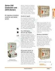
INSTRUMENT AND CONTRC<br />
ONTROL OL SWITCH<br />
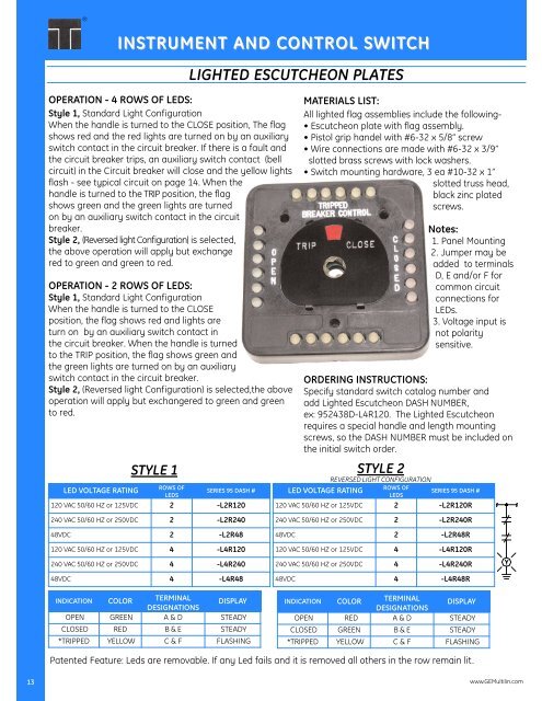
LIGHTED ESCUTCHEON PLATES<br />
OPERATION - 4 ROWS OF LEDS:<br />
Style 1, Standard Light Configuration<br />
When the handle is turned to the CLOSE position, The flag<br />
shows red and the red lights are turned on by an auxiliary<br />
switch contact in the circuit breaker. If there is a fault and<br />
the circuit breaker trips, an auxiliary switch contact (bell<br />
circuit) in the Circuit breaker will close and the yellow lights<br />
flash - see typical circuit on page 14. When the<br />
handle is turned to the TRIP position, the flag<br />
shows green and the green lights are turned<br />
MATERIALS LIST:<br />
All lighted flag assemblies include the following-<br />
• Escutcheon plate with flag assembly.<br />
• Pistol grip handel with #6-32 x 5/8” screw<br />
• Wire connections are made with #6-32 x 3/9”<br />
slotted brass screws with lock washers.<br />
• Switch mounting hardware, 3 ea #10-32 x 1”<br />
slotted truss head,<br />
black zinc plated<br />
screws.<br />
on by an auxiliary switch contact in the circuit<br />
breaker.<br />
Style 2, (Reversed light Configuration) is selected,<br />
the above operation will apply but exchange<br />
red to green and green to red.<br />
Notes:<br />
1. Panel Mounting<br />
2. Jumper may be<br />
added to terminals<br />
D, E and/or F for<br />
OPERATION - 2 ROWS OF LEDS:<br />
Style 1, Standard Light Configuration<br />
When the handle is turned to the CLOSE<br />
position, the flag shows red and lights are<br />
turn on by an auxiliary switch contact in<br />
the circuit breaker. When the handle is turned<br />
common circuit<br />
connections for<br />
LEDs.<br />
3. Voltage input is<br />
not polarity<br />
sensitive.<br />
to the TRIP position, the flag shows green and<br />
the green lights are turned on by an auxiliary<br />
switch contact in the circuit breaker.<br />
Style 2, (Reversed light Configuration) is selected,the above<br />
operation will apply but exchangered to green and green<br />
to red.<br />
ORDERING INSTRUCTIONS:<br />
Specify standard switch catalog number and<br />
add Lighted Escutcheon DASH NUMBER,<br />
ex: <strong>95</strong>2438D-L4R120. The Lighted Escutcheon<br />
requires a special handle and length mounting<br />
screws, so the DASH NUMBER must be included on<br />
the initial switch order.<br />
STYLE 1<br />
STYLE 2<br />
REVERSED LIGHT CONFIGURATION<br />
LED VOLTAGE RATING<br />
ROWS OF<br />
LEDS<br />
SERIES <strong>95</strong> DASH #<br />
LED VOLTAGE RATING<br />
ROWS OF<br />
LEDS<br />
SERIES <strong>95</strong> DASH #<br />
120 VAC 50/60 HZ or 125VDC 2 -L2R120<br />
120 VAC 50/60 HZ or 125VDC 2 -L2R120R<br />
240 VAC 50/60 HZ or 250VDC 2 -L2R240<br />
240 VAC 50/60 HZ or 250VDC 2 -L2R240R<br />
48VDC 2 -L2R48<br />
48VDC 2 -L2R48R<br />
120 VAC 50/60 HZ or 125VDC 4 -L4R120<br />
120 VAC 50/60 HZ or 125VDC 4 -L4R120R<br />
240 VAC 50/60 HZ or 250VDC 4 -L4R240<br />
240 VAC 50/60 HZ or 250VDC 4 -L4R240R<br />
48VDC 4 -L4R48<br />
48VDC 4 -L4R48R<br />
INDICATION<br />
COLOR<br />
TERMINAL<br />
DESIGNATIONS<br />
DISPLAY<br />
INDICATION<br />
COLOR<br />
TERMINAL<br />
DESIGNATIONS<br />
DISPLAY<br />
OPEN GREEN A & D STEADY<br />
CLOSED RED B & E STEADY<br />
*TRIPPED YELLOW C & F FLASHING<br />
OPEN RED A & D STEADY<br />
CLOSED GREEN B & E STEADY<br />
*TRIPPED YELLOW C & F FLASHING<br />
Patented Feature: Leds are removable. If any Led fails and it is removed all others in the row remain lit.<br />
13<br />
www.GEMultilin.com