Series CA8 Contactors and CAT8 Starters
Series CA8 Contactors and CAT8 Starters
Series CA8 Contactors and CAT8 Starters

Create successful ePaper yourself
Turn your PDF publications into a flip-book with our unique Google optimized e-Paper software.
<strong>Series</strong> <strong>CA8</strong><br />
<strong>Contactors</strong> <strong>and</strong><br />
<strong>CAT8</strong> <strong>Starters</strong><br />
An ingenious miniature<br />
contactor <strong>and</strong> starter<br />
system<br />
Sprecher + Schuh’s New <strong>CA8</strong> <strong>Series</strong><br />
of miniature contactors <strong>and</strong> starters<br />
provide an extremely compact <strong>and</strong><br />
reliable method of controlling motors<br />
of 7.5 HP or less (@460V). The<br />
<strong>CA8</strong> is an economical choice for<br />
applications where space is limited or<br />
where a minimal enclosure is desired.<br />
Small but rugged<br />
Even though their contacts <strong>and</strong> coils<br />
are not replaceable, Sprecher + Schuh<br />
has subjected this series of contactors<br />
to monitored endurance tests that<br />
demonstrate their ruggedness. At<br />
full load, under 3-phase power, the<br />
contacts in the <strong>CA8</strong> have an electrical<br />
life of 700,000 operations, while the<br />
AC magnet system has a mechanical<br />
life of 10,000,000 operations.<br />
The <strong>CAT8</strong> Starter –<br />
Efficient <strong>and</strong> reliable<br />
This miniature starter features the<br />
new CT8 Thermal Overload Relay. A<br />
complex current limiting calibration<br />
procedure performed after each unit<br />
is what ensures the consistent high<br />
quality of Sprecher + Schuh’s thermal<br />
overload relay. Today’s, Class 10<br />
T-frame design like the CT <strong>Series</strong><br />
has been recognized by many motor<br />
manufacturers as the ideal type to<br />
assure optimum motor protection due<br />
to less use of copper <strong>and</strong> iron.<br />
DRAFT<br />
shallow mounting depths. Once the<br />
<strong>CA8</strong> is installed, all auxiliary contact<br />
blocks can be snapped-on or removed<br />
without changing any existing power<br />
wiring. Other accessories include a<br />
snap-on RC Link (surge suppressor),<br />
mechanical interlocks <strong>and</strong> space saving<br />
adaptors for connecting auxiliary<br />
components.<br />
Effortless installation<br />
Both the <strong>CA8</strong> Contactor <strong>and</strong><br />
the <strong>CAT8</strong> Starter are DIN-rail<br />
mountable for instant installation <strong>and</strong><br />
modification. Fittings are also included<br />
on the <strong>CA8</strong> for base mounting. All<br />
terminals are clearly marked <strong>and</strong><br />
shipped in the open position for<br />
installation with either manual or<br />
power screwdrivers.<br />
A<br />
<strong>Contactors</strong><br />
<strong>CA8</strong><br />
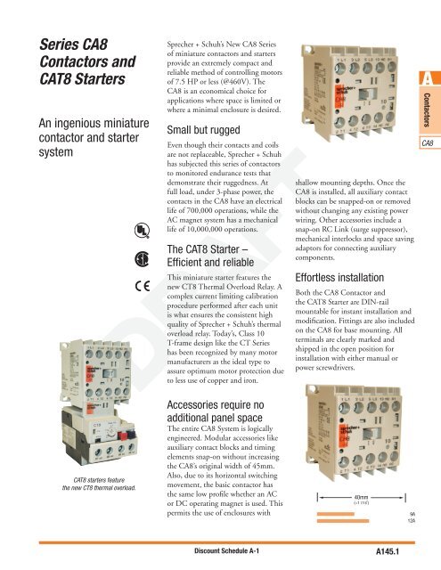
<strong>CAT8</strong> starters feature<br />
the new CT8 thermal overload.<br />
Accessories require no<br />
additional panel space<br />
The entire <strong>CA8</strong> System is logically<br />
engineered. Modular accessories like<br />
auxiliary contact blocks <strong>and</strong> timing<br />
elements snap-on without increasing<br />
the <strong>CA8</strong>’s original width of 45mm.<br />
Also, due to its horizontal switching<br />
movement, the basic contactor has<br />
the same low profile whether an AC<br />
or DC operating magnet is used. This<br />
permits the use of enclosures with<br />
40mm<br />
(≈1 7/16˝)<br />
9A<br />
12A<br />
Discount Schedule A-1<br />
A145.1
Catalog Number Coding<br />
Open <strong>Contactors</strong><br />
A<br />
<strong>Contactors</strong><br />
<strong>CA8</strong><br />
Catalog Number Coding<br />
Sprecher+Schuh employs a catalog number coding system<br />
for contactors (<strong>and</strong> many other devices) that follows a<br />
logical pattern, where every digit signifies a specific device<br />
attribute. Where indicated, the use of dashes (–) serves to<br />
separate device characteristics <strong>and</strong> should always be used<br />
when ordering.<br />
CA<br />
CAU<br />
CA<br />
Configuration<br />
Contactor<br />
Reversing<br />
Contactor<br />
8-9 - 10 - 24Z<br />
Contactor <strong>Series</strong><br />
<strong>Series</strong> <strong>CA8</strong> ➊<br />
8-9(C)<br />
8-12(C)<br />
The following example illustrates all of the possible<br />
combinations when specifying contactors <strong>and</strong> reversing<br />
contactors (open type only). See Section C for an<br />
explanation of the catalog number coding system for<br />
enclosed contactors <strong>and</strong> starters.<br />
Auxiliary Contacts<br />
-10 N.O. Auxiliary<br />
-01 N.C. Auxiliary<br />
4-pole <strong>CA8</strong> <strong>Contactors</strong> ➋<br />
-M40 4 N.O. Power Poles<br />
-M31 3 N.O. Power Poles/<br />
1 N.C. Power Pole<br />
-M22 2 N.O. Power Poles/<br />
2 N.C. Power Poles<br />
Coil Code<br />
DRAFT<br />
AC<br />
DC<br />
24(Z) 12D<br />
120 24D(D)<br />
208 48D<br />
240 110D<br />
380 220D<br />
480<br />
This illustration is for reference only.<br />
Turn to the appropriate page to determine<br />
specific catalog number & pricing.<br />
➊ (C) suffix designates DC contactors<br />
➋ On four pole contactors, this number designates main power pole configuration.<br />
A145.2<br />
Discount Schedule A-1
Miniature <strong>Contactors</strong> - AC & DC Coil<br />
<strong>Series</strong> <strong>CA8</strong><br />
Non-Reversing, Three Pole <strong>Contactors</strong> With AC Coil, <strong>Series</strong> <strong>CA8</strong> (Open type only) ➊<br />
I e<br />
[A]<br />
Non-Reversing, Three Pole <strong>Contactors</strong> With DC Coil, <strong>Series</strong> <strong>CA8</strong> (Open type only) ➊➋<br />
A.C. Coil Codes ➊➌<br />
Ratings for Switching AC Motors (AC2 / AC3 / AC4)<br />
kW (50 Hz)<br />
UL/CSA HP (60 Hz)<br />
1 Ø 3 Ø<br />
DRAFT<br />
D.C. Coil Codes ➊➌<br />
Auxiliary<br />
Contacts per<br />
Contactor<br />
400V<br />
AC-3 AC-1 230V 415V 500V 115V 230V 200V 230V 460V 575V NO NC<br />
9 20 3 4 4 1/2 1-1/2 2 2 5 5<br />
12 20 3 5.5 4 1/2 2 3 3 7-1/2 10<br />
I<br />
e<br />
[A]<br />
AC<br />
Coil Code<br />
Ratings for Switching AC Motors (AC2 / AC3 / AC4)<br />
kW (50 Hz)<br />
Voltage Range<br />
50 Hz 60 Hz<br />
12 12V 12V<br />
24Z 24V 24V<br />
48 48V 48V<br />
120 110V 120V<br />
208 200V-230V 200V-230V<br />
240 240V 240V<br />
380 380V-400V 400V-415V<br />
480 440V 440V-480V<br />
UL/CSA HP (60 Hz)<br />
1 Ø 3 Ø<br />
400V<br />
AC-3 AC-1 230V 415V 500V 115V 230V 200V 230V 460V 575V NO NC<br />
9 20 3 4 4 1/2 1-1/2 2 2 5 5<br />
12 20 3 5.5 4 1/2 2 3 3 7-1/2 10<br />
DC<br />
Coil Code Voltage<br />
12D 12V<br />
24D 24V ➍<br />
48D 48V<br />
110D 110V<br />
125D 125V<br />
220D 220V<br />
Open Type<br />
Catalog Number<br />
Price<br />
1 0 <strong>CA8</strong>-9-10-✱ 65<br />
0 1 <strong>CA8</strong>-9-01-✱ 65<br />
1 0 <strong>CA8</strong>-12-10-✱ 80<br />
0 1 <strong>CA8</strong>-12-01-✱ 80<br />
Auxiliary<br />
Open Type<br />
Contacts per<br />
Contactor<br />
Catalog Number<br />
Price<br />
1 0 <strong>CA8</strong>-9C-10-✱ 80<br />
0 1 <strong>CA8</strong>-9C-01-✱ 80<br />
1 0 <strong>CA8</strong>-12C-10-✱ 99<br />
0 1 <strong>CA8</strong>-12C-01-✱ 99<br />
<strong>CA8</strong>-9-10 contactor<br />
<strong>CA8</strong> to be introduced<br />
in 2007<br />
A<br />
<strong>Contactors</strong><br />
<strong>CA8</strong><br />
Ordering Instructions<br />
● Specify Catalog Number<br />
● Replace (✱) with Coil Code<br />
See Coil Code table on<br />
this page for codes<br />
➊ <strong>CA8</strong> not available without coil. Coils <strong>and</strong> contacts not replaceable.<br />
➋ Select Coil Code from D.C. Coil Code table only.<br />
➌ The coil codes shown are the most commonly stocked items. Contact your<br />
Sprecher + Schuh representative to determine if special voltages, are required.<br />
➍ Integrated diode surge suppressor coils available. Order coil code 24DD <strong>and</strong> add<br />
$25 to list price. Ex: <strong>CA8</strong>-9C-10-24D becomes <strong>CA8</strong>-9C-10-24DD.<br />
Discount Schedule A-1<br />
A145.3
Miniature <strong>Contactors</strong> - AC & DC Coil<br />
<strong>Series</strong> <strong>CA8</strong><br />
A<br />
<strong>Contactors</strong><br />
<strong>CA8</strong><br />
Non-Reversing, Four Pole <strong>Contactors</strong> With AC Coil, <strong>Series</strong> <strong>CA8</strong> (Open type only) ➊➍<br />
I<br />
e<br />
[A]<br />
Ratings for Switching AC Motors (AC2 / AC3 / AC4)<br />
kW (50 Hz)<br />
UL/CSA HP (60 Hz)<br />
1 Ø 3 Ø<br />
Contact<br />
configuration<br />
main poles<br />
400V<br />
AC-3 AC-1 230V 415V 500V 115V 230V 200V 230V 460V 575V NO NC<br />
9 20 3 4 4 1/2 1-1/2 2 2 5 5<br />
12 20 3 5.5 4 1/2 2 3 3 7-1/2 10<br />
Open Type<br />
Catalog Number<br />
Price<br />
4 0 <strong>CA8</strong>-9-M40-✱ 65<br />
3 1 <strong>CA8</strong>-9-M31-✱ 65<br />
2 2 <strong>CA8</strong>-9-M22-✱ 65<br />
4 0 <strong>CA8</strong>-12-M40-✱ 80<br />
3 1 <strong>CA8</strong>-12-M31-✱ 80<br />
2 2 <strong>CA8</strong>-12-M22-✱ 80<br />
Non-Reversing, Four Pole <strong>Contactors</strong> With DC Coil, <strong>Series</strong> <strong>CA8</strong> (Open type only) ➊➍<br />
I<br />
e<br />
[A]<br />
Ratings for Switching AC Motors (AC2 / AC3 / AC4)<br />
kW (50 Hz)<br />
UL/CSA HP (60 Hz)<br />
1 Ø 3 Ø<br />
Contact<br />
configuration<br />
main poles<br />
400V<br />
AC-3 AC-1 230V 415V 500V 115V 230V 200V 230V 460V 575V NO NC<br />
9 20 3 4 4 1/2 1-1/2 2 2 5 5<br />
12 20 3 5.5 4 1/2 2 3 3 7-1/2 10<br />
A.C. Coil Codes ➊➌<br />
AC<br />
Coil Code<br />
Voltage Range<br />
50 Hz 60 Hz<br />
12 12V 12V<br />
24Z 24V 24V<br />
48 48V 48V<br />
120 110V 120V<br />
208 200V-230V 200V-230V<br />
240 240V 240V<br />
380 380V-400V 400V-415V<br />
480 440V 440V-480V<br />
Open Type<br />
Catalog Number<br />
Price<br />
4 0 <strong>CA8</strong>-9C-M40-✱ 80<br />
3 1 <strong>CA8</strong>-9C-M31-✱ 80<br />
2 2 <strong>CA8</strong>-9C-M22-✱ 80<br />
4 0 <strong>CA8</strong>-12C-M40-✱ 99<br />
3 1 <strong>CA8</strong>-12C-M31-✱ 99<br />
2 2 <strong>CA8</strong>-12C-M22-✱ 99<br />
DRAFT<br />
D.C. Coil Codes ➊➌<br />
DC<br />
Coil Code Voltage<br />
12D 12V<br />
24D 24V ➎<br />
48D 48V<br />
110D 110V<br />
125D 125V<br />
220D 220V<br />
<strong>CA8</strong> to be introduced<br />
in 2007<br />
<strong>CA8</strong>-9-M40 contactor<br />
Ordering Instructions<br />
● Specify Catalog Number<br />
● Replace (✱) with Coil Code<br />
See Coil Code table on<br />
this page for codes<br />
➊ <strong>CA8</strong> not available without coil. Coils <strong>and</strong> contacts not replaceable.<br />
➋ Select Coil Code from D.C. Coil Code table only.<br />
➌ The coil codes shown are the most commonly stocked items. Contact your<br />
Sprecher + Schuh representative to determine if other voltages.<br />
➍ No auxiliary contacts provided in the base of a <strong>CA8</strong>. Add auxiliaries from pg.<br />
A145.8.<br />
➎ Integrated diode surge suppressor coils available. Order coil code 24DD <strong>and</strong> add<br />
$25 to list price. Ex: <strong>CA8</strong>-9C-10-24D becomes <strong>CA8</strong>-9C-10-24DD.<br />
A145.4<br />
Discount Schedule A-1
Miniature <strong>Contactors</strong> – Reversing<br />
<strong>Series</strong> CAU8<br />
Reversing, Three Pole <strong>Contactors</strong> With AC Coil, <strong>Series</strong> CAU8 (Open type only) ➊<br />
I [A]<br />
e<br />
Ratings for Switching AC Motors (AC2 / AC3 / AC4)<br />
kW (50 Hz)<br />
UL/CSA HP (60 Hz)<br />
1 Ø 3 Ø<br />
Auxiliary<br />
Contacts per<br />
Contactor<br />
400V<br />
AC-3 AC-1 230V<br />
415V 500V<br />
115V 230V 200V 230V 460V 575V NO NC<br />
9 20 3 4 4 1/2 1-1/2 2 2 5 5<br />
12 20 3 5.5 4 1/2 2 3 3 7-1/2 10<br />
Open Type<br />
Catalog Number<br />
Price<br />
0 1 CAU8-9-02-✱-LW 140<br />
2 1 CAU8-9-42-✱-PW 175<br />
0 1 CAU8-12-02-✱-LW 181<br />
2 1 CAU8-12-42-✱-PW 221<br />
Reversing, Three Pole <strong>Contactors</strong> With DC Coil, <strong>Series</strong> CAU8 (Open type only) ➊<br />
I e<br />
[A]<br />
Ratings for Switching AC Motors (AC2 / AC3 / AC4)<br />
kW (50 Hz)<br />
UL/CSA HP (60 Hz)<br />
1 Ø 3 Ø<br />
Auxiliary<br />
Contacts per<br />
Contactor<br />
400V<br />
AC-3 AC-1 230V 415V 500V 115V 230V 200V 230V 460V 575V NO NC<br />
9 20 3 4 4 1/2 1-1/2 2 2 5 5<br />
12 20 3 5.5 4 1/2 2 3 3 7-1/2 10<br />
A.C. Coil Codes ➊➌<br />
AC<br />
Coil Code<br />
Voltage Range<br />
50 Hz 60 Hz<br />
12 12V 12V<br />
24Z 24V 24V<br />
48 48V 48V<br />
120 110V 120V<br />
208 200V-230V 200V-230V<br />
240 240V 240V<br />
380 380V-400V 400V-415V<br />
480 440V 440V-480V<br />
Open Type<br />
Catalog Number<br />
Price<br />
0 1 CAU8-9C-02-✱-LW 140<br />
2 1 CAU8-9C-42-✱-PW 175<br />
0 1 CAU8-12C-02-✱-LW 181<br />
2 1 CAU8-12C-42-✱-PW 221<br />
DRAFT<br />
D.C. Coil Codes ➊➌<br />
DC<br />
Coil Code Voltage<br />
12D 12V<br />
24D 24V ➍<br />
48D 48V<br />
110D 110V<br />
125D 125V<br />
220D 220V<br />
CAU8…LW Includes:<br />
• Mechanical interlock<br />
CAU8…PW Includes:<br />
• Mechanical <strong>and</strong> electrical<br />
interlock ➋<br />
• Reversing power <strong>and</strong> control<br />
wiring (using Wiring Kit<br />
Cat.# CAUT8-PW)<br />
•Top mount auxiliary contact<br />
block (Cat.# <strong>CA8</strong>-P20)<br />
<strong>CA8</strong> to be introduced<br />
in 2007<br />
A<br />
<strong>Contactors</strong><br />
<strong>CA8</strong><br />
Ordering Instructions<br />
● Specify Catalog Number<br />
● Replace (✱) with Coil Code<br />
See Coil Code table on<br />
this page for codes<br />
➊ <strong>CA8</strong> not available without coil. Coils <strong>and</strong> contacts not replaceable.<br />
➋ Internal NC contacts on each contactor are used for electrical interlocking.<br />
➌ The coil codes shown are the most commonly stocked items. Contact your<br />
Sprecher + Schuh representative to determine if other voltages are required.<br />
➍ Integrated diode surge suppressor coils available. Order coil code 24DD <strong>and</strong> add<br />
$25 to list price. Ex: <strong>CA8</strong>-9C-10-24D becomes <strong>CA8</strong>-9C-10-24DD.<br />
Discount Schedule A-1<br />
A145.5
Miniature <strong>Starters</strong>, AC & DC Coil<br />
<strong>Series</strong> <strong>CAT8</strong><br />
A<br />
<strong>Contactors</strong><br />
<strong>CA8</strong><br />
Non-Reversing, Three Pole <strong>Starters</strong> With AC Coil, <strong>Series</strong> <strong>CAT8</strong> (Open type only) ➊<br />
I<br />
e<br />
[A]<br />
Ratings for Switching AC Motors (AC2 / AC3 / AC4)<br />
kW (50 Hz)<br />
UL/CSA HP (60 Hz)<br />
1 Ø 3 Ø<br />
Non-Reversing, Three Pole <strong>Starters</strong> With DC Coil, <strong>Series</strong> <strong>CAT8</strong> (Open type only) ➊➋<br />
NOTE: <strong>CAT8</strong> starters are priced to include Sprecher + Schuh’s economical<br />
CT8 bimetallic overload relay. See page A145.10 for selection.<br />
Auxiliary<br />
Contacts per<br />
Contactor<br />
400V<br />
AC-3 AC-1 230V 415V 500V 115V 230V 200V 230V 460V 575V NO NC<br />
9 20 3 4 4 1/2 1-1/2 2 2 5 5<br />
12 20 3 5.5 4 1/2 2 3 3 7-1/2 10<br />
I e<br />
[A]<br />
Ratings for Switching AC Motors (AC2 / AC3 / AC4)<br />
kW (50 Hz)<br />
UL/CSA HP (60 Hz)<br />
1 Ø 3 Ø<br />
400V<br />
AC-3 AC-1 230V 415V 500V 115V 230V 200V 230V 460V 575V NO NC<br />
9 20 3 4 4 1/2 1-1/2 2 2 5 5<br />
12 20 3 5.5 4 1/2 2 3 3 7-1/2 10<br />
A.C. Coil Codes ➊➌<br />
AC<br />
Coil Code<br />
Voltage Range<br />
50 Hz 60 Hz<br />
12 12V 12V<br />
24Z 24V 24V<br />
48 48V 48V<br />
120 110V 120V<br />
208 200V-230V 200V-230V<br />
240 240V 240V<br />
380 380V-400V 400V-415V<br />
480 440V 440V-480V<br />
Open Type<br />
Catalog Number<br />
Price<br />
1 0 <strong>CAT8</strong>-9-10-✱-◆ 102<br />
0 1 <strong>CAT8</strong>-9-01-✱-◆ 102<br />
1 0 <strong>CAT8</strong>-12-10-✱-◆ 122<br />
0 1 <strong>CAT8</strong>-12-01-✱-◆ 122<br />
Auxiliary<br />
Open Type<br />
Contacts per<br />
Contactor<br />
Catalog Number<br />
Price<br />
1 0 <strong>CAT8</strong>-9C-10-✱-◆ 121<br />
0 1 <strong>CAT8</strong>-9C-01-✱-◆ 121<br />
1 0 <strong>CAT8</strong>-12C-10-✱-◆ 141<br />
0 1 <strong>CAT8</strong>-12C-01-✱-◆ 141<br />
Representative model of a <strong>CAT8</strong>-9…<br />
starter with the CT8 bimetallic<br />
overload relay<br />
DRAFT<br />
D.C. Coil Codes ➊➌<br />
DC<br />
Coil Code<br />
12D<br />
24D<br />
48D<br />
110D<br />
125D<br />
220D<br />
Voltage<br />
12V<br />
24V ➍<br />
48V<br />
110V<br />
125V<br />
220V<br />
<strong>CA8</strong> to be introduced<br />
in 2007<br />
Ordering Instructions<br />
● Specify Catalog Number<br />
● Replace (✱) with Coil Code<br />
● Replace (◆) with O/L Relay Code ➌<br />
Coil Codes on this page<br />
O/L Relay Code on A15.10<br />
➊ <strong>CA8</strong> not available without coil. Coils <strong>and</strong> contacts not replaceable.<br />
➋ Select Coil Code from D.C. Coil Code table only.<br />
➌ The coil codes shown are the most commonly stocked items. Contact your<br />
Sprecher + Schuh representative to determine if other voltages are required.<br />
➍ Integrated diode surge suppressor coils available. Order coil code 24DD <strong>and</strong> add<br />
$25 to list price. Ex: <strong>CA8</strong>-9C-10-24D becomes <strong>CA8</strong>-9C-10-24DD.<br />
A145.6<br />
Discount Schedule A-1
Miniature <strong>Starters</strong>, AC <strong>and</strong> DC Coil – Reversing<br />
<strong>Series</strong> CAUT8<br />
Reversing, Three Pole <strong>Starters</strong> With AC Coil, <strong>Series</strong> CAUT8 (Open type only) ➊➋<br />
I e<br />
[A]<br />
Ratings for Switching AC Motors (AC2 / AC3 / AC4)<br />
kW (50 Hz)<br />
UL/CSA HP (60 Hz)<br />
1 Ø 3 Ø<br />
Auxiliary<br />
Contacts per<br />
Contactor<br />
400V<br />
AC-3 AC-1 230V 415V 500V 115V 230V 200V 230V 460V 575V NO NC<br />
9 20 3 4 4 1/2 1-1/2 2 2 5 5<br />
12 20 3 5.5 4 1/2 2 3 3 7-1/2 10<br />
Open Type<br />
Catalog Number<br />
Price<br />
0 1 CAUT8-9-02-✱-◆-LW 182<br />
2 1 CAUT8-9-42-✱-◆-PW 217<br />
0 1 CAUT8-12-02-✱-◆-LW 222<br />
2 1 CAUT8-12-42-✱-◆-PW 257<br />
Non-Reversing, Three Pole <strong>Starters</strong> With DC Coil, <strong>Series</strong> CAUT8 (Open type only) ➊➋<br />
I e<br />
[A]<br />
Ratings for Switching AC Motors (AC2 / AC3 / AC4)<br />
kW (50 Hz)<br />
UL/CSA HP (60 Hz)<br />
1 Ø 3 Ø<br />
400V<br />
AC-3 AC-1 230V 415V 500V 115V 230V 200V 230V 460V 575V NO NC<br />
9 20 3 4 4 1/2 1-1/2 2 2 5 5<br />
12 20 3 5.5 4 1/2 2 3 3 7-1/2 10<br />
A.C. Coil Codes ➊➌<br />
AC<br />
Coil Code<br />
Voltage Range<br />
50 Hz 60 Hz<br />
12 12V 12V<br />
24Z 24V 24V<br />
48 48V 48V<br />
120 110V 120V<br />
208 200V-230V 200V-230V<br />
240 240V 240V<br />
380 380V-400V 400V-415V<br />
480 440V 440V-480V<br />
Auxiliary<br />
Open Type<br />
Contacts per<br />
Contactor<br />
Catalog Number<br />
Price<br />
1 0 CAUT8-9C-10-✱-◆-LW xxx<br />
0 1 CAUT8-9C-01-✱-◆-PW xxx<br />
1 0 CAUT8-12C-10-✱-◆-LW xxx<br />
0 1 CAUT8-12C-01-✱-◆-PW xxx<br />
DRAFT<br />
D.C. Coil Codes ➊➌<br />
DC<br />
Coil Code Voltage<br />
12D 12V<br />
24D 24V ➍<br />
48D 48V<br />
110D 110V<br />
125D 125V<br />
220D 220V<br />
CAUT8…LW Includes:<br />
• Mechanical interlock<br />
• Utilizes CT8 bimetallic<br />
overload relay. Select code<br />
from page C78.2.<br />
CAUT8…PW Includes:<br />
• Mechanical <strong>and</strong><br />
electrical interlock ➋<br />
• Reversing power <strong>and</strong> control<br />
wiring (using Wiring Kit Cat.#<br />
CAUT8-PW)<br />
•Top mount auxiliary contact<br />
block (Cat.# <strong>CA8</strong>-P20)<br />
<strong>CA8</strong> to be introduced<br />
in 2007<br />
A<br />
<strong>Contactors</strong><br />
<strong>CA8</strong><br />
Ordering Instructions<br />
● Specify Catalog Number<br />
● Replace (✱) with Coil Code<br />
● Replace (◆) with O/L Relay Code<br />
Coil Codes on this page<br />
O/L Relay Code on A145.10<br />
➊ <strong>CA8</strong> not available without coil. Coils <strong>and</strong> contacts not replaceable.<br />
➋ NC contacts on each contactor are used for electrical interlocking.<br />
➌ The coil codes shown are the most commonly stocked items. Contact<br />
your Sprecher + Schuh representative to determine if other voltages are<br />
required.<br />
➍ Integrated diode surge suppressor coils available. Order coil code 24DD <strong>and</strong><br />
add $25 to list price. Ex: <strong>CA8</strong>-9C-10-24D becomes <strong>CA8</strong>-9C-10-24DD.<br />
Discount Schedule A-1<br />
A145.7
Accessories - Field Installable<br />
<strong>CA8</strong> Miniature <strong>Contactors</strong> <strong>and</strong> <strong>Starters</strong><br />
A<br />
<strong>Contactors</strong><br />
Auxiliary Contact Blocks (2 & 4 Pole) ➊<br />
Auxiliary<br />
Contact Blocks NO NC<br />
Contact<br />
Arrangement Catalog No. Price<br />
<br />
1 1 <strong>CA8</strong>-P11<br />
Auxiliary<br />
Contact Blocks NO NC<br />
Contact<br />
Arrangement Catalog No. Price<br />
1 1 CS8-P11E<br />
<strong>CA8</strong><br />
2-Pole<br />
Typical auxiliary<br />
contact block<br />
4-Pole<br />
Control Modules ➋<br />
Module<br />
0 2 <strong>CA8</strong>-P02<br />
2 0 <strong>CA8</strong>-P20<br />
<br />
2 2 <strong>CA8</strong>-P22<br />
<br />
<br />
3 1 <strong>CA8</strong>-P31<br />
<br />
<br />
1 3 <strong>CA8</strong>-P13<br />
<br />
<br />
0 4 <strong>CA8</strong>-P04<br />
<br />
<br />
4 0 <strong>CA8</strong>-P40<br />
<br />
Description<br />
Pluggable electronic timer –<br />
ON-Delay<br />
The contactor is energized at the<br />
end of the delay time.<br />
DRAFT<br />
For use<br />
with...<br />
<strong>CA8</strong> all<br />
14<br />
25<br />
2-Pole<br />
Typical auxiliary<br />
contact block<br />
4-Pole<br />
0 2 CS8-P02E<br />
2 0 CS8-P20E<br />
2 2 CS8-P22Z<br />
3 1 CS8-P31Z<br />
1 3 CS8-P13Z<br />
0 4 CS8-P04E<br />
4 0 CS8-P40E<br />
1+<br />
1EM<br />
1+<br />
1EB<br />
Connection<br />
Diagrams Function Catalog Number Price<br />
110...250V 50/60Hz<br />
0.1...3 sec<br />
1...30 sec<br />
24...48VDC<br />
0.1...3 sec<br />
1...30 sec<br />
<br />
<br />
<br />
<br />
<br />
<br />
<br />
<br />
53 63 73 83<br />
54 64 74 84<br />
<br />
<br />
CS8-PL22Z<br />
CRZE8-3-110/240<br />
CRZE8-30-110/240<br />
CRZE8-3-24/48VDC<br />
CRZE8-30-24/48VDC<br />
60<br />
14<br />
25<br />
Pluggable electronic timer –<br />
OFF-Delay<br />
The timer switches off after the set<br />
time has elapsed<br />
<strong>CA8</strong> all<br />
110...250V 50/60Hz<br />
1...30 sec CRZA8-30-110/240<br />
24...48VDC<br />
1...30 sec CRZA8-30-24/48VDC<br />
60<br />
➊ Auxiliary contacts are mechanically linked (positively guided). Contacts are<br />
bifurcated (H-bridge) with a minimum rating of 17V @ 5mA.<br />
A145.8<br />
Discount Schedule A-1
Accessories - Field Installable<br />
<strong>CA8</strong> Miniature <strong>Contactors</strong> & <strong>Starters</strong><br />
Miscellaneous Accessories<br />
Accessory Description Catalog Number Price<br />
Surge Suppressor CR__8 - for limiting voltage<br />
spikes when switching off coil. Coil itself provides<br />
sufficient limitation at voltages over 240V.<br />
RC Link (Type CRC8…) for AC Control<br />
24-48VAC<br />
110-280VAC<br />
380-480VAC<br />
Diode Link (Type CRD8…) for DC Control ➊<br />
12-250VDC (diode)<br />
Varistor Link (Type CRV8…)for AC/DC Control<br />
12-55VAC/12-77VDC<br />
56-136VAC/78-178VDC<br />
137-277VAC/181-350VDC<br />
Mechanical Interlock Kit -<br />
For interlocking of two adjacet contactor<br />
– without additional space requirement in width<br />
– attachable from the front<br />
– optional auxiliary contact blocks to be mounted on<br />
the top (does not interfere with mounting CR__8)<br />
Wiring Kit -<br />
For connecting line, load <strong>and</strong> control wiring of a CAU8<br />
reversing contactor.<br />
Connection Modules -<br />
For KTA7 motor circuit controller with a <strong>CA8</strong> contactor.<br />
CRC8-50<br />
CRC8-280<br />
CRC8-480<br />
CRD8-250<br />
CRV8-55<br />
CRV8-136<br />
CRV8-277<br />
DRAFT<br />
Adaptor -<br />
For mounting CRZE8 <strong>and</strong> CRZA8 Electronic Timers to<br />
DIN-rails.<br />
20<br />
20<br />
13<br />
CM8 10<br />
CAUT8-PW 10<br />
KT7-25S-PEK12 24<br />
25.950.207-01 3<br />
A<br />
<strong>Contactors</strong><br />
<strong>CA8</strong><br />
<strong>CA8</strong> to be introduced<br />
in 2007<br />
➊ <strong>CA8</strong> contactors with DC coils can be special ordered with integrated<br />
diodes (built-in) rather than applying CRD8 to the coil terminals.<br />
Discount Schedule A-1<br />
A145.9
Overload Relay Codes<br />
<strong>Series</strong> <strong>CA8</strong> <strong>Starters</strong><br />
A<br />
<strong>Contactors</strong><br />
<strong>CA8</strong><br />
<strong>CAT8</strong> <strong>Starters</strong> with<br />
CT8 Thermal Overload Relay<br />
For us with<br />
contactor....<br />
Amp<br />
Range<br />
Overload<br />
Relay<br />
Code (◆)<br />
Catalog Number<br />
(of Overload Relay used)<br />
Price<br />
Adder<br />
CT8 Thermal Overload Relay, 1 or 3-Phase, Auto/Manual, Class 10<br />
<strong>CA8</strong>-9<br />
0.10…0.16 8A16 CT8-A16 St<strong>and</strong>ard<br />
0.16...0.25 8A25 CT8-A25 St<strong>and</strong>ard<br />
0.25...0.4 8A40 CT8-A40 St<strong>and</strong>ard<br />
0.35...0.5 8A50 CT8-A50 St<strong>and</strong>ard<br />
0.45...0.63 8A63 CT8-A63 St<strong>and</strong>ard<br />
0.55...0.8 8A80 CT8-A80 St<strong>and</strong>ard<br />
0.75...1.0 8B10 CT8-B10 St<strong>and</strong>ard<br />
0.90...1.3 8B13 CT8-B13 St<strong>and</strong>ard<br />
1.10...1.6 8B16 CT8-B16 St<strong>and</strong>ard<br />
1.4...2.0 8B20 CT8-B20 St<strong>and</strong>ard<br />
1.8...2.5 8B25 CT8-B25 St<strong>and</strong>ard<br />
2.3...3.2 8B23 CT8-B32 St<strong>and</strong>ard<br />
2.9...4.0 8B40 CT8-B40 St<strong>and</strong>ard<br />
3.5...4.8 8B48 CT8-B48 St<strong>and</strong>ard<br />
4.5...6.3 8B63 CT8-B63 St<strong>and</strong>ard<br />
5.5...7.5 8B75 CT8-B75 St<strong>and</strong>ard<br />
<strong>CA8</strong>-9 or 12 7.2...10 8C10 CT8-C10 St<strong>and</strong>ard<br />
<strong>CA8</strong>-12 9.0...12.5 8C12 CT8-C12 St<strong>and</strong>ard<br />
DRAFT<br />
<strong>CA8</strong> AND <strong>CAT8</strong> to be<br />
introduced in 2007<br />
A145.10<br />
Discount Schedule A-1
Technical Information<br />
<strong>CA8</strong> Miniature <strong>Contactors</strong><br />
Technical Information<br />
<strong>CA8</strong>-9 <strong>CA8</strong>-12 <strong>CA8</strong>-9 <strong>CA8</strong>-12<br />
Rated Insulation Voltage U i Wye-Delta (Star Delta) 230V [A] 21 21<br />
to IEC947-1 [V] 500V 50 Hz 240V [A] 21 21<br />
UL/CSA [V] 600V 400V [A] 16 21<br />
Rated Impulse Voltage U imp 415V [A] 16 21<br />
Rated Voltage Ue-Main Contacts 500V [A] 12 12<br />
AC 50/60Hz [V] 230, 240, 400, 415, 500 230V [kW] 5.5 5.5<br />
DC [V] 24, 48, 110, 220, 440 240V [kW] 5.5 5.5<br />
Operating Frequency for AC Loads [Hz] 50/60Hz 400V [kW] 7.5 10<br />
415V [kW] 7.5 11<br />
Switching Motor Loads 500V [kW] 7.5 7.5<br />
St<strong>and</strong>ard IEC Ratings AC-1 Load, 3∅ Switching I e [A] 20 20<br />
AC-2, AC-3 230 [A] 12 12 Ambient Temperature 40˚ C 230V [kW] 8 8<br />
DOL & Reversing 240V [A] 12 12 240V [kW] 8.3 8.3<br />
50Hz/60˚ C 400V [A] 9 12 400V [kW] 14 14<br />
415V [A] 9 12 415V [kW] 14 14<br />
500V [A] 7 7 500V [kW] 17 17<br />
230V [kW] 3.3 3.3 Ambient Temperature 60˚ C I e [A] 16 16<br />
240V [kW] 3.4 3.4 230V [kW] 6.4 6.4<br />
400V [kW] 4.3 5.5 240V [kW] 6.7 6.7<br />
415V [kW] 4.5 6.1 400V [kW] 11 11<br />
500V [kW] 4.2 4.2 415V [kW] 12 12<br />
500V [kW] 14 14<br />
UL/CSA 115V [A] 9.8 9.8 Continuous Current (UL/CSA)<br />
DOL & Reversing 1∅ 230V [A] 10 12 General Purpose Rating (40˚ C) Open [A] 12 12<br />
60Hz 115V [HP] 0.5 0.5 Enclosed [A] 12 12<br />
230V [HP] 1.5 2<br />
200V [A] 7.8 11 Lighting Loads Enclosed [A] 18 18<br />
230V [A] 6.8 9.6 Elec.Dischrg.Lamps-AC-5a, Open [A] 14.5 14.5<br />
460 V [A] 7.6 11 single compensated<br />
3∅ 575 V [A] 6.1 11 Max. capacitance at 10kA [µF] 750 750<br />
200 V [HP] 2 3 prospective short circuit 20kA [µF] 400 400<br />
230 V [HP] 2 3 current available at the 50kA [µF] ~ ~<br />
460 V [HP] 5 7.5 contactor<br />
575 V [HP] 5 10 Inc<strong>and</strong>escent Lamps<br />
- AC-5b<br />
Maximum Operating Rate AC2 [ops/hour] 300 300 Electrical endurance~100,000 operations [A] 9.3 9.3<br />
At 9A for AC3; 20A for AC2/4 AC3 [ops/hour] 600 600<br />
Starting time t A = 0.25s AC4 [ops/hour] 300 300<br />
AC4 (200,000 Op. Cycles) 230V [A] 3.9 3.9<br />
50Hz 240V [A] 3.9 3.9<br />
400V [A] 3.3 3.3<br />
415V [A] 3.2 3.2<br />
230V [kW] 0.75 0.75<br />
240V [kW] 0.75 0.75<br />
400V [kW] 1.1 1.1<br />
415V [kW] 1.5 1.5<br />
Max. Operating Rate [ops/hour] 250 250<br />
DRAFT<br />
A<br />
<strong>Contactors</strong><br />
<strong>CA8</strong><br />
Discount Schedule A-1<br />
A145.11
Technical Information<br />
<strong>CA8</strong> Miniature <strong>Contactors</strong><br />
A<br />
<strong>Contactors</strong><br />
<strong>CA8</strong><br />
Electrical Data<br />
<strong>CA8</strong>-9<br />
<strong>CA8</strong>-12<br />
Short Circuit Protection of <strong>CA8</strong> Without<br />
Motor Protection Relays<br />
Switching power transformers AC-6a<br />
Max. fuse gG per IEC<br />
947-4-1<br />
Inrush = n Type 1 Coordination max. [A] 25 25<br />
Rated transformer current Type 2 Coordination max. [A] 16 16<br />
230V [A] 5.4 5.4 Class K5 <strong>and</strong> RK5 fuses ➊ max. [A] 40 40<br />
240V [A] 5.4 5.4 Resistance <strong>and</strong> Watt Loss l e AC3<br />
400V [A] 4.1 5.4 Resistance per power pole [mΩ] 5.5<br />
415V [A] 4.1 5.4 Watt Loss - 3 power poles [W] 2.4<br />
500V [A] 3.2 3.2 Coil <strong>and</strong> 3 AC [W] 3.8<br />
230VAC [kVA] 2.2 2.2 power poles DC [W] 4.9<br />
240VAC [kVA] 2.2 2.2<br />
400VAC [kVA] 2.8 3.7<br />
415VAC [kVA] 2.9 3.9<br />
500VAC [kVA] 2.7 2.7<br />
DC Ratings<br />
DC-1 Rating at 60°C [kW] ~ ~<br />
1 Pole 24VDC [A] 9 9<br />
48VDC [A] 6 6<br />
110VDC [A] 1 1<br />
220VDC [A] 0.3 0.3<br />
440VDC [A] 0.1 0.1<br />
2 Pole in <strong>Series</strong> 24VDC [A] 9 9<br />
48VDC [A] 8 8<br />
110VDC [A] 6 6<br />
220VDC [A] 1.2 1.2<br />
440VDC [A] 0.3 0.3<br />
3 Pole in <strong>Series</strong> 24VDC [A] 9 9<br />
48VDC [A] 9 9<br />
110VDC [A] 9 9<br />
220VDC [A] 4 4<br />
440VDC [A] 0.6 0.6<br />
Shunt-wound Motors<br />
Starting, reverse current braking, reversing<br />
stepping DC-3, 60°C<br />
24V [A] 9 9<br />
3 Poles in series 48/60V [A] 6 6<br />
110V [A] 3 3<br />
220V [A] 1.2 1.2<br />
440V [A] 0.2 0.2<br />
<strong>Series</strong>-wound Motors<br />
Starting, reverse current braking, reversing<br />
stepping DC-5, 60°C<br />
24V [A] 9 9<br />
3 poles in series 48/60V [A] 3 3<br />
110V [A] 1 1<br />
220V [A] 0.1 0.1<br />
440V [A] ~ ~<br />
Short Time Withst<strong>and</strong>-I CW , 60°C<br />
10s [A] 96 96<br />
Coil Data<br />
<strong>CA8</strong>-9<br />
DRAFT<br />
<strong>CA8</strong>-12<br />
<strong>CA8</strong>-9 <strong>CA8</strong>-12<br />
Voltage Range<br />
AC: 50Hz, 60Hz, 50/60 Hz Pickup `[x Us] 0.85...1.1<br />
Dropout [x Us] 0.3...0.65<br />
DC Pickup [x Us] 0.85...1.1<br />
Dropout [x Us] 0.1...0.25<br />
Coil Consumption<br />
AC: 50Hz, 60Hz, 50/60 Hz Pickup [VA/W] 22/20<br />
Hold-in [VA/W] 4/1.4<br />
DC Pickup [W] 2.5<br />
Hold-in [W] 2.5<br />
Operating Times<br />
AC: 50Hz, 60Hz, 50/60 Hz Pickup [ms] 15...40<br />
Dropout [ms] 15...25<br />
with RC Suppressor Dropout [ms] 15...25<br />
DC Pickup [ms] 18...40<br />
Dropout [ms] 6...12<br />
with Integ. Suppression Dropout [ms] 8...12<br />
with Diode Suppression Dropout [ms] 35...50<br />
➊ UL listed combination.<br />
A145.12<br />
Discount Schedule A-1
Technical Information<br />
<strong>CA8</strong> Miniature <strong>Contactors</strong><br />
Mechanical Data<br />
Service Life<br />
<strong>CA8</strong>-9<br />
Mechanical AC [Mil.] 10<br />
DC [Mil.] 20<br />
Electrical AC-3(400V) [Mil.] 0.7<br />
Shipping Weights<br />
AC-<strong>CA8</strong> [kg] 0.16<br />
[Lbs] 0.35<br />
AC-CAU8 [kg] 0.35<br />
[Lbs] 0.77<br />
DC-<strong>CA8</strong> [kg] 0.16<br />
[Lbs] 0.35<br />
DC-CAU8 [kg] 0.35<br />
[Lbs] 0.77<br />
Terminations - Power<br />
Terminal Type<br />
1 wire<br />
2 wires<br />
1 wire<br />
2 wires<br />
1 wire<br />
2 wires<br />
<strong>CA8</strong>-12<br />
Combination Screw Head: Cross, Slotted, Pozidrive<br />
[mm 2 ]<br />
[mm 2 ]<br />
[mm 2 ]<br />
[mm 2 ]<br />
[AWG]<br />
[AWG]<br />
0.75...2.5<br />
0.75...2.5<br />
0.75...2.5<br />
0.75...2.5<br />
18...14<br />
18...14<br />
Torque Requirement [Nm] 1...1.5<br />
[Lb-in] 7...15<br />
Terminations - Control<br />
Terminal Type<br />
Combination Screw Head: Cross, Slotted, Pozidrive<br />
Coils 1 or 2 [mm 2 ] 0.75...2.5<br />
Wires [AWG] 18...14<br />
Control Modules 1 or 2 [mm 2 ] 0.75...2.5<br />
Wires [AWG] 18...14<br />
Torque Requirement [Nm] 1...1.5<br />
[Lb-in] 7...15<br />
Degree of Protection-contactor IEC 60529 <strong>and</strong> DIN 40 050 (with wires installed)<br />
Protection Against<br />
Safe from touch by fingers <strong>and</strong> back-of h<strong>and</strong><br />
Accidental Contact per VDE 0106; Part 100<br />
Environmental <strong>and</strong> General Specifications<br />
Ambient Temperature<br />
Storage -55...+80˚ C (-67...176˚ F)<br />
Operation -25...+60˚ C (-13...140˚ F)<br />
Conditioned 15% current -25...+70˚ C (-13...158˚ F)<br />
reduction after AC-1 at >60˚ C<br />
Altitude at installed site 2000 meters above sea level per IEC 947-4<br />
Resistance to Corrosion / Humidity<br />
Shock Resistance<br />
Damp-alternating climate: cyclic to IEC 68-2, 56 cycles.<br />
Dry Heat: IEC 68-2, +100°C (212°F), relative humidity
Technical Information<br />
<strong>CA8</strong> Miniature <strong>Contactors</strong><br />
A<br />
<strong>Contactors</strong><br />
<strong>CA8</strong><br />
Auxiliary Contacts<br />
Built-in Auxiliary Contacts<br />
Add-on Auxiliary Contact Blocks<br />
Current Switching<br />
AC-12 Ith at 40°C [A] 16 10<br />
at 60°C [A] 12 6<br />
AC-15, switching electromagnetic loads at: [V] 24...230 240 400 415 500 24...230 240 400 415 500<br />
[A] 6 5 2.5 2 1.25 2 2 1 1 0.6<br />
DC-13, switching DC electromagnets at: [V] 24 48 110 220 440 24 48 110 22 440<br />
[A] 5 0.6 0.45 0.25 0.04 2 0.6 0.45 0.1 0.04<br />
Low Level Signal Switching<br />
Contact design X-stamped H-bridge, bi-furcated<br />
Minimum switching recommendation [V] 17V 17V<br />
[mA] 10mA 5mA<br />
Short-Circuit Protection - gG Fuse<br />
Type 2 Coordination [A] 16 10<br />
Load carrying capacity per UL/CSA<br />
Rated Voltage AC [V] 600 max. 600 max.<br />
Continuous Rating 40°C [A] 10 general purpose 10 general purpose<br />
Switching Capacity AC Heavy pilot duty (A600) Heavy pilot duty (A600)<br />
Rated Voltage DC [V]<br />
Continuous Rating DC 600 max. 600 max.<br />
Switching Capacity DC St<strong>and</strong>ard pilot duty (Q600) St<strong>and</strong>ard pilot duty (Q600)<br />
Terminals<br />
Terminal Type<br />
Maximum Wire Size per IEC 947-1<br />
.<br />
Flexible with Wire- 1 Conductor [mm 2 ]<br />
0.75...2.5 0.75...2.5<br />
End Fernule 2 Conductor [mm 2 ]<br />
0.75...2.5 0.75...2.5<br />
Solid/Str<strong>and</strong>ed- 1 Conductor [mm 2 ]<br />
0.75...2.5 0.75...2.5<br />
Conductor 2 Conductor [mm 2 ]<br />
0.75...2.5 0.75...2.5<br />
Recommended Tightening Torque [Nm] 1...15 1...1.5<br />
Max. Wire Size per UL/CSA [AWG] 18...14 18...14<br />
Recommended Tightening Torque [lb-in] 7...15 7...15<br />
CRZE8 Electronic Timers<br />
Permissible voltage<br />
CRZE8 (AC or DC) 110V (-23%) - 250V (+10%)<br />
110V (-23%) - 120V (+10%)<br />
110V (-23%) - 250V (+10%)<br />
Voltage Drop<br />
5V max<br />
Load current for reliable operation 10mA min<br />
Load current<br />
20°C<br />
600mA<br />
40°C<br />
440mA<br />
55°C<br />
320mA<br />
Leakage current at 220V<br />
CRZE8<br />
5mA<br />
Reset time<br />
200ms<br />
Voltage failure duration having no<br />
influence on timing sequence<br />
CRZE8<br />
15ms<br />
Repeat accuracy ±5%<br />
Time interval for start comm<strong>and</strong>s<br />
CRZE8<br />
1.4 x set time<br />
Ambient Temperature<br />
Storage<br />
Operation<br />
-40°C to +80°C<br />
-20°C to +55°C<br />
DRAFT<br />
Contact Ratings (Per NEMA/UL A600 & Q600)<br />
St<strong>and</strong>ard<br />
A600<br />
Q600<br />
Circuit<br />
Voltage<br />
120AC<br />
240AC<br />
480AC<br />
600AC<br />
125DC<br />
250DC<br />
301-600DC<br />
Make<br />
(Amps/VA)<br />
60A/7200VA<br />
30A/7200VA<br />
15A/7200VA<br />
12A/7200VA<br />
0.55/69VA<br />
0.27/69VA<br />
0.1A/69VA<br />
Mechanically Linked<br />
(Positively-Guided Contacts ➊)<br />
SUVA Certified<br />
Break<br />
(Amps/VA)<br />
60A/720VA<br />
30A/720VA<br />
15A/720VA<br />
12A/720VA<br />
0.55/69VA<br />
0.27/69VA<br />
0.1A/69VA<br />
• <strong>CA8</strong> Contactor contacts are linked among each other.<br />
• <strong>CA8</strong>/CS8 Auxiliary contact block contacts next to each other.<br />
• Contacts between <strong>CA8</strong> contactor <strong>and</strong> <strong>CA8</strong>/CS8 auxiliary<br />
contact block are not positively guided.<br />
Continuous<br />
Amps<br />
10<br />
2.5<br />
➊ See Section G for additional details.<br />
A145.14<br />
Discount Schedule A-1
Technical Information<br />
<strong>CA8</strong> Miniature <strong>Contactors</strong><br />
Determining Contact Life<br />
To determine the contactor’s estimated electrical life, follow these<br />
guidelines:<br />
1. Identify the appropriate Utilization Category from Table A.<br />
2. On the following pages, choose the graph for the Utilization Category<br />
selected.<br />
3. Locate the Rated Operational Current (l e ) along the bottom of the<br />
chart <strong>and</strong> follow the graph lines up to the intersection of the appropriate<br />
contactor’s life-load curve.<br />
4. Read the estimated contact life along the vertical axis.<br />
A<br />
<strong>Contactors</strong><br />
Table A – IEC Special Utilization Categories, AC Ratings ➊<br />
CONTACTORS<br />
CONTROL DEVICES<br />
SWITCHES<br />
Category Typical Applications<br />
Rated Current<br />
Conditions for testing<br />
electrical life<br />
Conditions for testing making <strong>and</strong><br />
breaking capacity<br />
Make Break<br />
Ops.<br />
Make Break<br />
I/Ie U/Ue cos Ic/Ie Ur/Ue cos I/Ie U/Ue cos Ic/Ie Ur/Ue cos<br />
Non-inductive or slightly<br />
AC-1 inductive loads, resistance All values 1 1 0.95 1 1 0.95 6000 1.5 1.05 0.8 1.5 1.05 0.8 50<br />
furnaces<br />
AC-2<br />
Slip-ring motors:<br />
Starting, plugging<br />
All values 2 1.05 0.65 2 1.05 0.65 6000 4 1.05 0.65 4 1.05 0.65 50<br />
Squirrel-cage motors:<br />
Ie 17Amp<br />
6 1 0.65 1 0.17 0.65 10 1.1 0.65 8 1.1 0.65<br />
AC-3 Starting, switching off motors 17Amp100Amp 6 1 0.35 1 0.17 0.35 8 ➋ 1.1 0.35 6 ➌ 1.1 0.35<br />
AC-4<br />
Ie 17Amp<br />
6 1 0.65 6 1 0.65 12 1.1 0.65 10 1.1 0.65<br />
Squirrel-cage motors:<br />
17Amp100Amp 6 1 0.35 6 1 0.35 10➍ 1.1 0.35 8 ➋ 1.1 0.35<br />
50<br />
AC-5a<br />
Switching of electric discharge<br />
lamp control<br />
2 1.05 0.45 2 1.05 0.45 6000 3 1.05 0.45 3 1.05 0.45 50<br />
AC-5b Switching of inc<strong>and</strong>escent lamps 1 1.05 1 1.05 1.5 1.05 1.5 1.05 50<br />
AC-6a Switching of transformers Rating derived from AC-3 rating (x 0.45)<br />
AC-6b Switching of capacity banks Depends on circuit conditions of application<br />
Control of resistive loads <strong>and</strong> solid<br />
AC-12 state loads with isolation All values 1 1 0.9 1 1 0.9 6050<br />
by opto couplers<br />
AC-13<br />
Control of solid state loads with<br />
transformer isolation<br />
2 1 0.65 1 1 0.65 6050 10 1.1 0.65 1.1 1.1 0.65 10<br />
AC-14<br />
Control of small electromagnetic<br />
loads<br />
72 VA 6 1 0.3 1 1 0.3 6050 6 1.1 0.7 6 1.1 0.7 10<br />
AC-15 Control of electromagnetic loads 72 VA 10 1 0.3 1 1 0.3 6050 10 1.1 0.3 10 1.1 0.3 10<br />
AC-20<br />
Connecting <strong>and</strong> disconnecting<br />
under no load conditions<br />
No testing required<br />
AC-21<br />
Switching of resistive loads,<br />
including moderate loads<br />
All values 1 1 0.95 1 1 0.95 10000 1.5 1.05 0.95 1.5 1.05 0.95 5<br />
Switching of mixed resistive &<br />
AC-22 inductive loads, including All values 1 1 0.8 1 1 0.8 10000 3 1.05 0.65 3 1.05 0.65 5<br />
moderate overloads<br />
AC-23<br />
Switching of motor loads or other<br />
highly inductive loads<br />
All values 1 1 0.65 1 1 0.65 10000 10 1.05 0.45 8 1.05 0.45 5<br />
DRAFT<br />
Ops.<br />
<strong>CA8</strong><br />
Legend<br />
Ue Rated operational voltage<br />
U Voltage before make<br />
Ur Recovery voltage<br />
Ie Rated operational current<br />
I Making current<br />
Ic Breaking current<br />
L Inductance of test circuit<br />
R Resistance of test circuit<br />
➊ Utilization categories <strong>and</strong> test conditions for AC & DC. For contactors according to<br />
IEC 158-1, starters according to IEC 292-1 ... 4 <strong>and</strong> control switches according to<br />
IEC 337-1 <strong>and</strong> IEC 337-1A.<br />
➋ With a minimum value of 1000A for I or Ic.<br />
➌ With a minimum value of 800A for Ic.<br />
➍ With a minimum value of 1200A for I.<br />
➎ Plugging is understood as stopping or reversing the motor rapidly by reversing<br />
the motor primary connections while the motor is running. Inching [or jogging] is<br />
understood as energizing a motor once or repeatedly for short periods to obtain<br />
small movements of the driven mechanism.<br />
Discount Schedule A-1<br />
A145.15
Technical Information<br />
<strong>CA8</strong> <strong>Contactors</strong> - Contact Life<br />
A<br />
<strong>Contactors</strong><br />
Determining Contact Life<br />
To determine the contactor’s estimated electrical life, follow these<br />
guidelines:<br />
1. Identify the appropriate Utilization Category from Table A.<br />
2. On the following pages, choose the graph for the Utilization<br />
Category selected.<br />
3. Locate the Rated Operational Current (l e ) along the bottom of<br />
the chart <strong>and</strong> follow the graph lines up to the intersection of<br />
the appropriate contactor’s life-load curve.<br />
4. Read the estimated contact life along the vertical axis.<br />
<strong>CA8</strong><br />
Table A – IEC Special Utilization Categories, DC Ratings ➊<br />
Conditions for testing<br />
electrical life<br />
Conditions for testing making <strong>and</strong> breaking<br />
capacity<br />
Category Typical Applications Rated Current Make Break Ops Make Break Ops<br />
I/Ie U/Ue cos Ic/Ie Ur/Ue cos I/Ie U/Ue cos Ic/Ie Ur/Ue cos<br />
DC-1<br />
Non-inductive or slightly<br />
inductive loads, resistance All values 1 1 1 1 1 1 1.5 ➋ 1.1 ➋ 1 ➋ 1.5 ➋ 1.1 ➋ 1 ➋<br />
furnaces<br />
Shunt-motors:<br />
DC-2 Starting, switching off motors<br />
during running<br />
All values 2.5 1 2 1 0.1 7.5 4 1.1 2.5 4 1.1 2.5<br />
DC-3<br />
DC-4<br />
DC-5<br />
DC-15<br />
Shunt-motors:<br />
Starting, plugging, inching<br />
<strong>Series</strong>-motors:<br />
Starting switching off motors<br />
during running<br />
<strong>Series</strong>-motors:<br />
Starting, plugging, inching<br />
Electromagnets for contactors,<br />
valves, solenoid actuators<br />
All values 2.5 1 2 2.5 1 2 4 1.1 2.5 4 1.1 2.5<br />
All values 2.5 1 7.5 1 0.3 10 4 1.1 15 4 1.1 15<br />
All values 2.5 1 7.5 2.5 1 7.5 4 1.1 15 4 1.1 15<br />
All values 1 1 6 x P ➌ 1 1 6 x P ➌ 1.1 1.1 6 x P ➌ 1.1 1.1 6 x P ➌<br />
DRAFT<br />
Legend<br />
Ue Rated operational voltage<br />
U Voltage before make<br />
Ur Recovery voltage<br />
Ie Rated operational current<br />
I Making current<br />
Ic Breaking current<br />
L Inductance of test circuit<br />
R Resistance of test circuit<br />
A145.16<br />
➊ Utilization categories <strong>and</strong> test conditions for AC & DC. For contactors according to IEC 158-1,<br />
starters according to IEC 60292-1 ... 4 <strong>and</strong> control switches according to IEC 337-1 <strong>and</strong> IEC<br />
337-1A.<br />
➋ Only according to VDE.<br />
➌ P = Ue x Ie rated power [W]. The value “6 x P” has been derived from an empiric relationship<br />
which covers most magnetic loads for DC up to an upper limit of P = 50W.<br />
Discount Schedule A-1
Technical Information<br />
<strong>CA8</strong> Miniature <strong>Contactors</strong> – Life Load Curves<br />
Life-Load Curves<br />
• Locate the Rated Operational<br />
Current (l e ) along the bottom of<br />
the chart <strong>and</strong> follow the graph<br />
lines up to the intersection of the<br />
appropriate contactor’s life-load<br />
curve.<br />
• Read the estimated contact life<br />
along the vertical axis.<br />
INSTRUCTIONS ON<br />
“HOW TO READ”<br />
LIFE CURVES CAN BE<br />
FOUND ON PG. A57.<br />
AC-1, AC3<br />
(400...460V AC)<br />
<br />
<br />
AC-4<br />
(400...460V AC)<br />
<br />
<br />
<br />
<br />
<br />
<br />
➊<br />
<br />
<br />
<br />
<br />
<br />
<br />
<br />
<br />
<br />
DRAFT<br />
<br />
<br />
<br />
<br />
<br />
<br />
➊<br />
<br />
<br />
A<br />
<strong>Contactors</strong><br />
<strong>CA8</strong><br />
<br />
<br />
<br />
NOTE: The life-load curves shown here are based on Sprecher+Schuh tests<br />
according to the requirements defined in IEC 60947-4-1. Since contact life in any<br />
given application is dependent on environmental conditions <strong>and</strong> duty cycle, actual<br />
application contact life may vary from that indicated by the curves shown here.<br />
➊ For electrical life at 460V (60Hz), reduce the values from the 400/415VAC (50Hz)<br />
chart by 5%.<br />
Discount Schedule A-1<br />
A145.17
Dimensions<br />
<strong>CA8</strong> Miniature <strong>Contactors</strong><br />
A<br />
<strong>Contactors</strong><br />
<strong>Series</strong> <strong>CA8</strong> & <strong>Series</strong> CAU8 (<strong>Contactors</strong> & Reversing <strong>Contactors</strong>)<br />
• Dimensions are in millimeters (inches) • Dimensions not intended for manufacturing purposes<br />
44.8<br />
<strong>CA8</strong><br />
DRAFT<br />
A145.18<br />
Discount Schedule A-1
<strong>Series</strong> CT8<br />
Thermal Overload<br />
Relays<br />
Simple <strong>and</strong> effective<br />
motor protection<br />
for applications to<br />
7 1 /2HP@ 460V<br />
(10HP@575V)<br />
R<br />
Sprecher + Schuh has been a leader in<br />
providing superior motor protection.<br />
The new CT8 is an economical<br />
thermal overload relay yet includes<br />
proven features like “Differential<br />
tripping”, Automatic / Manual reset<br />
modes, <strong>and</strong> isolated alarm circuit<br />
contacts as st<strong>and</strong>ards.<br />
Consistent <strong>and</strong> reliable<br />
protection<br />
The consistent high quality of<br />
Sprecher + Schuh thermal overload<br />
relays is ensured by a complex current<br />
calibration procedure performed<br />
after each unit is at full operating<br />
temperature. Calibration is performed<br />
at the largest <strong>and</strong> smallest current the<br />
overload can h<strong>and</strong>le. The accurate<br />
time/current characteristic curve<br />
obtained in this manner guarantees<br />
reliable motor protection every time.<br />
Superior Class 10<br />
characteristics<br />
Today’s T-Frame motors have less<br />
copper <strong>and</strong> iron that the old U-Frame<br />
motors that were popular when<br />
traditional Class 20 overload relays<br />
were designed. For this reason, faster<br />
Class 10 overloads like the CT8 <strong>Series</strong><br />
have been recognized by many motor<br />
manufacturers as the ideal type to<br />
assure optimum protection of “T”<br />
frame motors.<br />
DRAFT<br />
Protection from single<br />
phase conditions<br />
A unique feature not found in<br />
traditional thermal overload relays<br />
provides accelerated tripping<br />
under single phase conditions.<br />
This is accomplished with a special<br />
“differential tripping” mechanism built<br />
into CT7 (see illustration at right).<br />
Ambient temperature<br />
compensation<br />
All Sprecher + Schuh thermal overload<br />
relays are temperature compensated.<br />
An additional bimetallic ambient<br />
compensation strip, built into the<br />
conductor-bimetal transmission path,<br />
ensures that the tripping characteristics<br />
of the relay remain constant over an<br />
ambient temperature range of<br />
–25°C to +50°C.<br />
Single phase applications<br />
CT8 <strong>Series</strong> thermal overload relays<br />
can be applied for protection of single<br />
phase AC motors. The relays have the<br />
same characteristics as shown for three<br />
phase operation. To maintain these<br />
characteristics, each element of the<br />
overload relay must carry the motor<br />
current as shown in the schematic on<br />
page C88.<br />
Other st<strong>and</strong>ard features<br />
CT8 thermal overload relays feature<br />
a fail-safe “trip-free” design that<br />
prevents the device from being held<br />
closed during an overload. In addition,<br />
a selectable lever permits the user<br />
the option to choose the manual or<br />
automatic reset modes.<br />
A separate NO signal contact is also<br />
provided on CT8 overloads which is<br />
isolated from the NC trip contact.<br />
This permits the use of a trip signal<br />
voltage different than that of the<br />
control voltage.<br />
Sprecher + Schuh provides outst<strong>and</strong>ing motor<br />
protection with our CT8 Thermal Overload Relay<br />
CT8 Thermal Overload Relays offer accelerated<br />
tripping under single phase conditions<br />
B32.1
Thermal Overload Relays<br />
<strong>Series</strong> CT8<br />
A<br />
<strong>Contactors</strong><br />
<strong>CA8</strong><br />
CT8 Thermal Overload Relays, Manual Reset ➊<br />
Overload Relay<br />
CT8<br />
Directly Mounts<br />
to Contactor...<br />
CT8 Thermal Overload Relay Accessories<br />
Adjustment<br />
Ranges [A]<br />
Trip Class 10<br />
Catalog Number<br />
Price<br />
0.10…0.16 CT8-A16<br />
0.16…0.25 CT8-A25<br />
0.25…0.4 CT8-A40<br />
0.35… 0.5 CT8-A50<br />
0.45…0.63 CT8-A63<br />
0.55…0.80 CT8-A80<br />
0.75…1.0 CT8-B10<br />
<strong>CA8</strong>-9<br />
0.90…1.3 CT8-B13<br />
1.10…1.6 CT8-B16<br />
42<br />
1.4…2.0 CT8-B20<br />
1.8…2.5 CT8-B25<br />
2.3…3.2 CT8-B32<br />
2.9…4.0 CT8-B40<br />
3.5...4.8 CT8-B48<br />
4.5…6.3 CT8-B63<br />
5.5…7.5 CT8-B75<br />
<strong>CA8</strong>-9 or 12 7.2...10 CT8--C9 46<br />
<strong>CA8</strong>-12 9.0...12.5 CT8-C12 46<br />
Accessories Description For Use with... Catalog Number<br />
CMR8 Remote Reset Coil Codes<br />
AC<br />
Coil Code<br />
Voltage Range<br />
50 Hz 60 Hz<br />
24Z 24V 24V<br />
120 110V 120V<br />
240 240V 240V<br />
Remote Reset -<br />
For remote resetting of the solid state<br />
overload relay<br />
All<br />
CT8<br />
CT8 to be introduced<br />
in 2007<br />
DRAFT<br />
DC<br />
Coil Code<br />
24D<br />
48D<br />
115D<br />
Voltage<br />
24V<br />
48V<br />
115V<br />
Price<br />
Each<br />
CMR8-✱ 47<br />
B32.2<br />
Discount Schedule A-1
Dimensions<br />
<strong>Series</strong> CT8 Thermal Overload Relays<br />
<br />
1) With aux contact block <strong>CA8</strong>-P.<br />
2) With timing elements CRZE8, CRZA8.<br />
<br />
<strong>Series</strong> <strong>CAT8</strong> (Mounting to <strong>CA8</strong> Contactor)<br />
<br />
<br />
<br />
<br />
<br />
<br />
<br />
<br />
<br />
<br />
<br />
<br />
<br />
<br />
DRAFT<br />
<br />
<br />
<br />
<br />
<br />
A<br />
<strong>Contactors</strong><br />
<strong>CA8</strong><br />
Discount Schedule A-1 B32.3
CS8<br />
Industrial<br />
Control<br />
Relays<br />
The miniature relay<br />
system with big<br />
advantages<br />
CS8 front mount auxiliaries are<br />
positive guidance<br />
R<br />
Despite increasing complexity, control<br />
systems <strong>and</strong> installations must become<br />
increasingly compact. And the CS8<br />
Miniature Relay System packs maximum<br />
performance into minimum space.<br />
Small but rugged<br />
Sprecher + Schuh has subjected this<br />
relay series to monitored endurance<br />
tests that demonstrate their ruggedness.<br />
Under normal duty, CS8 contacts<br />
have a maximum electrical life of<br />
3,500,000 operations, while the AC<br />
magnet system has a mechanical life of<br />
10,000,000 operations.<br />
The coil is designed for absolute<br />
undervoltage reliability. Undervoltages<br />
that do not cause the contactor to close<br />
can be withstood indefinitely without<br />
damage.<br />
The body of the device is sturdy as<br />
well. The front housing, containing the<br />
phase partitions <strong>and</strong> screwdriver guides,<br />
is manufactured in one piece. Front<br />
<strong>and</strong> rear housing are then joint fitted<br />
together.<br />
Superior Contact Reliability<br />
The st<strong>and</strong>ard CS8 base relay <strong>and</strong><br />
auxiliary contacts are bifurcated<br />
H-bridge design which divides each<br />
movable contact into two sections at<br />
the tip of the spanner which provides<br />
a higher degree of reliability for low<br />
signal applications. Perfect fit for PLC<br />
<strong>and</strong> other electronic circuits operate at<br />
signals as low as 17V @ 5mA.<br />
DRAFT<br />
Mechanically linked contacts<br />
for safety<br />
CS8 control relays are perfect for<br />
fail-safe control circuits. An interlock<br />
contact design, which maintains<br />
minimum 0.3mm clearance, prevents<br />
the NC contact from reclosing if<br />
the NO contact is welded when in<br />
operation. This feature includes the<br />
base contact poles <strong>and</strong> front mounted<br />
auxiliary contacts.<br />
Accessories require no<br />
additional panel space<br />
The entire CS8 system is logically<br />
engineered. Auxiliary contact blocks<br />
<strong>and</strong> timing elements are modular <strong>and</strong><br />
snap-on without increasing the CS8’s<br />
original width of 45mm. Also, due to its<br />
sideways switching movement, the basic<br />
relay has the same low profile whether<br />
an AC or DC operating magnet is used.<br />
This permits the use of enclosures with<br />
shallow mounting depths. Once the<br />
CS8 is installed, all auxiliary contact<br />
blocks can be snapped on or removed<br />
without changing any existing wiring.<br />
Auxiliary components<br />
provide flexibility<br />
CS8 auxiliary components allow you to<br />
convert the basic four pole relay up to<br />
an 8 pole relay.<br />
Effortless installation<br />
CS8 relays are DIN-rail mountable for<br />
instant installation <strong>and</strong> modification.<br />
Fittings are also included for base<br />
mounting. All terminals are clearly<br />
marked <strong>and</strong> shipped in the open<br />
position for installation with either<br />
manual or power screwdrivers. Using<br />
self-adhesive labels, paper tags or plastic<br />
clip-on tags.<br />
The entire line is UL Listed <strong>and</strong> CSA<br />
Certified <strong>and</strong> offers finger <strong>and</strong> back<br />
of h<strong>and</strong> protection to the strictest<br />
international st<strong>and</strong>ards.<br />
G<br />
Control &<br />
Timing Relays<br />
CS8<br />
Discount Schedule B G12.1
Industrial Control Relays<br />
<strong>Series</strong> CS8<br />
G<br />
Control &<br />
Timing Relays<br />
CS8<br />
CS8 Complete Assemblies - 4 Pole ➌<br />
CS8 Relay<br />
A.C. Coil Codes ➊<br />
AC Voltage Range<br />
Coil Code 50 Hz 60 Hz<br />
12 12V 12V<br />
24Z 24V 24V<br />
48 48V 48V<br />
120 110V 120V<br />
208 200V-230V 200V-230V<br />
240 240V 240V<br />
380 380V-400V 400V-415V<br />
480 440V 440V-480V<br />
Contact Arrangement <strong>and</strong><br />
Numbering<br />
A1<br />
A2<br />
A1<br />
A2<br />
A1<br />
A2<br />
13 23 33 43<br />
14 24 34 44<br />
13 33 43 21<br />
14 34 44 22<br />
13 43 21 31<br />
14 44 22 32<br />
<br />
<br />
Contact Ratings (Per UL508/NEMA A300 & Q300)<br />
St<strong>and</strong>ard<br />
A300<br />
Q300<br />
Circuit<br />
Voltage<br />
120AC<br />
240AC<br />
125DC<br />
250DC<br />
Make<br />
(Amps/VA)<br />
60A/7200VA<br />
30A/7200VA<br />
0.55A/69VA<br />
0.27A/69VA<br />
<br />
<br />
Break<br />
(Amps/VA)<br />
6A/720VA<br />
3A/720VA<br />
0.55A/69VA<br />
0.27A/69VA<br />
DRAFT<br />
D.C. Coil Codes ➊<br />
DC<br />
Coil Code Voltage<br />
12D 12V<br />
24D 24V ➋<br />
48D 48V<br />
110D 110V<br />
125D 125V<br />
220D 220V<br />
Contacts AC Operation DC Operation<br />
NO NC Catalog Number Price Catalog Number Price<br />
4 0 CS8-40E-✱<br />
47<br />
CS8C-40E-✱<br />
3 1 CS8-31Z-✱ CS8C-31Z-✱<br />
2 2 CS8-22Z-✱ CS8C-22Z-✱<br />
1+<br />
1EM<br />
Continuous<br />
Amps<br />
10<br />
2.5<br />
1+<br />
1LB<br />
CS8-L22Z-✱<br />
CS8C-L22Z-✱<br />
59<br />
Ordering Instructions<br />
• Specify catalog number<br />
• Replace (✱) with Coil Code<br />
Refer to tables<br />
above<br />
➊ The coil codes shown are for the most commonly stocked items. Contact<br />
your Sprecher + Schuh representative to determine if other voltages are<br />
on-h<strong>and</strong> or can be specially ordered in quantity.<br />
➋ Integrated diode surge suppressor coils available. Order coil code 24DD<br />
<strong>and</strong> add $25 to list price. Ex: CS8C-40E-24D becomes CS8-40E-24DD.<br />
➌ CS8 relays are positively guided for 4 main poles <strong>and</strong> auxiliary contacts.<br />
G12.2<br />
Discount Schedule B
Industrial Control Relays<br />
<strong>Series</strong> CS8<br />
Auxiliary Contact Blocks (2 & 4 Pole) ➊<br />
Auxiliary<br />
Contact Blocks NO NC<br />
2-Pole<br />
Typical auxiliary<br />
contact block<br />
4-Pole<br />
Control Modules ➋<br />
Module<br />
Contact<br />
Arrangement Catalog No. Price<br />
<br />
1 1 <strong>CA8</strong>-P11<br />
0 2 <strong>CA8</strong>-P02<br />
2 0 <strong>CA8</strong>-P20<br />
<br />
2 2 <strong>CA8</strong>-P22<br />
<br />
<br />
3 1 <strong>CA8</strong>-P31<br />
<br />
<br />
1 3 <strong>CA8</strong>-P13<br />
<br />
<br />
0 4 <strong>CA8</strong>-P04<br />
<br />
<br />
4 0 <strong>CA8</strong>-P40<br />
<br />
DRAFT<br />
Description<br />
Pluggable electronic timer –<br />
ON-Delay<br />
The relay is energized at the end of<br />
the delay time.<br />
For use<br />
with...<br />
CS8 all<br />
14<br />
25<br />
Auxiliary<br />
Contact Blocks NO NC<br />
2-Pole<br />
Typical auxiliary<br />
contact block<br />
4-Pole<br />
Connection<br />
Diagrams Function Catalog Number Price<br />
110...250V 50/60Hz<br />
0.1...3 sec<br />
1...30 sec<br />
24...48VDC<br />
0.1...3 sec<br />
1...30 sec<br />
Contact<br />
Arrangement Catalog No. Price<br />
1 1 CS8-P11E<br />
0 2 CS8-P02E<br />
2 0 CS8-P20E<br />
2 2 CS8-P22Z<br />
3 1 CS8-P31Z<br />
1 3 CS8-P13Z<br />
0 4 CS8-P04E<br />
4 0 CS8-P40E<br />
1+<br />
1EM<br />
1+<br />
1EB<br />
<br />
<br />
<br />
<br />
<br />
<br />
<br />
<br />
53 63 73 83<br />
54 64 74 84<br />
<br />
<br />
CS8-PL22Z<br />
CRZE8-3-110/240<br />
CRZE8-30-110/240<br />
CRZE8-3-24/48VDC<br />
CRZE8-30-24/48VDC<br />
14<br />
25<br />
60<br />
G<br />
Control &<br />
Timing Relays<br />
CS8<br />
Pluggable electronic timer –<br />
OFF-Delay<br />
The timer switches off after the set<br />
time has elapsed<br />
CS8 all<br />
110...250V 50/60Hz<br />
1...30 sec CRZA8-30-110/240<br />
24...48VDC<br />
1...30 sec CRZA8-30-24/48VDC<br />
60<br />
➊ Auxiliary contacts are mechanically linked (positively guided). Contacts are<br />
bifurcated (H-bridge) with a minimum rating of 17V @ 5mA.<br />
➋ Auxiliary contact ratings per UL 508/NEMA (A600/Q600).<br />
Discount Schedule B G12.3
Industrial Control Relays<br />
<strong>Series</strong> CS8<br />
G<br />
Control &<br />
Timing Relays<br />
CS8<br />
Miscellaneous Accessories<br />
Marking Systems<br />
Component<br />
Accessory Description Catalog Number Price<br />
Surge Suppressor CR__8 - for limiting voltage<br />
spikes when switching off coil. Coil itself provides<br />
sufficient limitation at voltages over 240V.<br />
RC Link (Type CRC8…) for AC Control<br />
24-48VAC<br />
110-280VAC<br />
380-480VAC<br />
Diode Link (Type CRD8…) for DC Control ➊<br />
12-250VDC (diode)<br />
Varistor Link (Type CRV8…)for AC/DC Control<br />
12-55VAC/12-77VDC<br />
56-136VAC/78-178VDC<br />
137-277VAC/181-350VDC<br />
Adaptor -<br />
For mounting CRZE8 <strong>and</strong> CRZA8 Electronic Timers to<br />
DIN-rails.<br />
Description<br />
Label Sheet –<br />
1 sheet with 105 self-adhesive paper<br />
labels each, 6 x 17mm<br />
Marking Tag Sheet -<br />
1 sheet with 160 perforated paper labels<br />
each, 6 x 17mm. To be used with<br />
transparent cover.<br />
Transparent Cover -<br />
To be used with Marking Tag Sheets.<br />
Pkg.<br />
Qty.<br />
Catalog Number<br />
CRC8-50<br />
CRC8-240<br />
CRC8-480<br />
CRD8-250<br />
CRV8-55<br />
CRV8-136<br />
CRV8-277<br />
DRAFT<br />
Tag Carrier -<br />
For marking with Clip-on Tags. See<br />
Terminals Section N for complete listing of<br />
Clip-on Tags.<br />
20<br />
20<br />
13<br />
25.950.207-01 3<br />
Price<br />
Each<br />
1 CA7-FMS 1<br />
1 CA7-FMP 1<br />
100<br />
➋<br />
100<br />
➋<br />
CA7-FMC<br />
CA7-FMA2<br />
.10<br />
.10<br />
➊ CS8 contactors with DC coils can be special ordered with integrated<br />
diodes (built-in) rather than applying CRD8 to the coil terminals.<br />
G12.4<br />
➋ Minimum order quantity is one package of 100. Price each x 100 = total price.<br />
Discount Schedule B
Industrial Control Relays<br />
<strong>Series</strong> CS8<br />
Technical Information<br />
CS8 Auxiliary Contacts<br />
Electrical<br />
Contact Ratings — NEMA A300, Q300 A600, Q600<br />
Contact Ratings — IEC<br />
AC-15 (solenoids, contactors)<br />
12…120V [A] 2.5 10<br />
at rated voltage<br />
220…240V [A] 2.0 5<br />
IEC 947, EN 60947<br />
360…400V [A] 2.0 2.5<br />
480…500V [A] 2.0 1.25<br />
AC-1 (Non-inductive, or<br />
slightly inductive loads,<br />
40°C [A] 10 16<br />
resistance furnaces)<br />
IEC947, EN 60947<br />
60°C [A] 6 12<br />
AC-2, AC-3, AC-4<br />
230V [A] 5 ~<br />
(switching 3Ø motors)<br />
400V [A] 3.7 ~<br />
500V [A] 2.8 ~<br />
Low Level Signal Switching<br />
Contact design H-bridge bi-furcated H-bridge bi-furcated<br />
Minimum switching<br />
recommendation<br />
17V<br />
5mA<br />
17V<br />
5mA<br />
Short Circuit Protection afforded by relay<br />
Coordination Type 2<br />
Fuse gG [A] 16 ~<br />
acc. IEC 947-4-1<br />
Fuse aM [A] 16 ~<br />
Switching DC<br />
Non-inductive or slightly<br />
inductive loads, resistance<br />
furnaces DC-1 at 60°C<br />
1 pole 24…48V [A] ~ ~<br />
110V [A] ~ ~<br />
220V [A] ~ ~<br />
440V [A] ~ ~<br />
2 poles in series 24…48V [A] ~ ~<br />
110V [A] ~ ~<br />
220V [A] ~ ~<br />
440V [A] ~ ~<br />
3 poles in series 24…48V [A] ~ ~<br />
110V [A] ~ ~<br />
220V [A] ~ ~<br />
440V [A] ~ ~<br />
Ratings according to UL/CSA<br />
Operating voltage AC [V] 115 ~<br />
AC [V] 200 ~<br />
AC [V] 230 ~<br />
AC [V] ~ ~<br />
AC [V] ~ ~<br />
Cont. Rating (general purpose) 300V [V] 10 ~<br />
600V [V] 10<br />
DRAFT<br />
G<br />
Control &<br />
Timing Relays<br />
CS8<br />
Discount Schedule B<br />
G12.5
Industrial Control Relays<br />
<strong>Series</strong> CS8<br />
G<br />
Control &<br />
Timing Relays<br />
CS8<br />
Technical Information<br />
CS8 Relays<br />
Mechanical<br />
Mechanical Life [Mil] 10<br />
Electrical Life<br />
AC-15 (240V, 3A) AC Operations [Mil] ~<br />
AC-1 (230V, 6A) [Mil] 0.7<br />
Weight [g] 153<br />
Terminal Cross-Sections<br />
Terminal Type<br />
1 Conductor<br />
2 Conductor<br />
1 Conductor<br />
2 Conductor<br />
[mm 2 ]<br />
[mm 2 ]<br />
[mm 2 ]<br />
[mm 2 ]<br />
0.75…2.5<br />
0.75…2.5<br />
0.75…2.5<br />
0.75…2.5<br />
Max. Wire Size [AWG] 18…14<br />
Tightening Torque [Nm] 1…1.5<br />
[lb-in] 7…15<br />
Control Circuit<br />
Operating Voltage<br />
AC 50/60 Hz Pickup [x U s ] 0.85…1.1<br />
Dropout [x U s ] 0.35…0.65<br />
DC Pickup [x U s ] 0.8…1.1<br />
Dropout [x U s ] 0.1…0.25<br />
with protection circuit Dropout [U max /U min ] 1…1.2<br />
Coil Consumption<br />
AC 50/60 Hz Inrush [VA/W] 22 / 20<br />
Seal [VA/W] 4 / 1.4<br />
DC Inrush/Seal [W] 2.5<br />
Operating Times<br />
AC- 50/60 Hz Pickup Time [ms] 15…40<br />
Dropout Time [ms] 15…25<br />
DC Pickup Time [ms] 18…40<br />
Dropout Time [ms] 6…12<br />
with protection circuit Dropout [ms] 8…12<br />
General<br />
Rated Voltage Withst<strong>and</strong> U<br />
IEC<br />
500V<br />
UL; CSA<br />
600V<br />
High voltage - 1 minute (per IEC 947-4)<br />
2500V<br />
Rated Impulse Strength U imp<br />
8 kV<br />
Rated Voltage U e<br />
AC<br />
230, 240, 400, 415, 500V<br />
DC<br />
24, 48, 110, 220, 440V<br />
Rated Frequency<br />
50/60 Hz, DC<br />
Ambient Temperature<br />
Storage<br />
–55...+80°C (–67...176°F)<br />
Operation at nominal current<br />
–25...+60°C (–13...140°F)<br />
At 85% rated operation current<br />
–25...+70ºC (–13... 158ºF)<br />
Resistance to Climatic Change 40º C (104º F), 95% relative humidity,<br />
56 days<br />
23º C (73.4 º F), 83%/40 ºC (104 ºF), 93%,<br />
56 cycles<br />
Altitude 2000m M.S.L., per IEC 947-4<br />
Type of Protection<br />
IP 20 (IEC 529 <strong>and</strong> DIN 40050)<br />
in connected state<br />
Finger Protection<br />
safe from touch by fingers <strong>and</strong> back of<br />
h<strong>and</strong> per VDE 0106, Part 100<br />
CRZE8 Electronic Timers<br />
Permissible voltage<br />
CRZE8 (AC or DC) 110V (-23%) - 250V (+10%)<br />
110V (-23%) - 120V (+10%)<br />
220V (-20%) - 250V (+10%)<br />
Voltage drop<br />
5V max<br />
Load current for reliable operation 10mA min<br />
Load current<br />
20°C (68º F) 600mA<br />
40°C (104º F) 440mA<br />
55°C (131º F) 320mA<br />
Leakage current at 220V<br />
CRZE8<br />
5mA<br />
Reset time<br />
≥200ms<br />
Voltage failure duration having no influence on timing sequence<br />
CRZE8<br />
15ms<br />
Repeat accuracy<br />
At fixed temperature ±1%<br />
With temperature range of<br />
±5%<br />
5...+55ºC (+23...+131º F)<br />
Time interval for start comm<strong>and</strong>s<br />
CRZE8<br />
1.4 x set time<br />
Ambient temperature<br />
Storage -40°C to +80°C (-40...+176º F)<br />
Operation -20°C to +55°C (-4...+131º F)<br />
Terminals: 0.8 mm 2 (AWG 18)<br />
CRZE8<br />
2 free cable ends, each 250 mm long<br />
DRAFT<br />
G12.6<br />
Discount Schedule B
Industrial Control Relays<br />
<strong>Series</strong> CS8<br />
<strong>Series</strong> CS8 Industrial Control Relays<br />
G<br />
Control &<br />
Timing Relays<br />
CS8<br />
Auxiliary contact block with screw terminals: +30mm depth<br />
DRAFT<br />
Discount Schedule B G12.7