Series CA8 Contactors and CAT8 Starters
Series CA8 Contactors and CAT8 Starters
Series CA8 Contactors and CAT8 Starters

Create successful ePaper yourself
Turn your PDF publications into a flip-book with our unique Google optimized e-Paper software.
Technical Information<br />
<strong>CA8</strong> <strong>Contactors</strong> - Contact Life<br />
A<br />
<strong>Contactors</strong><br />
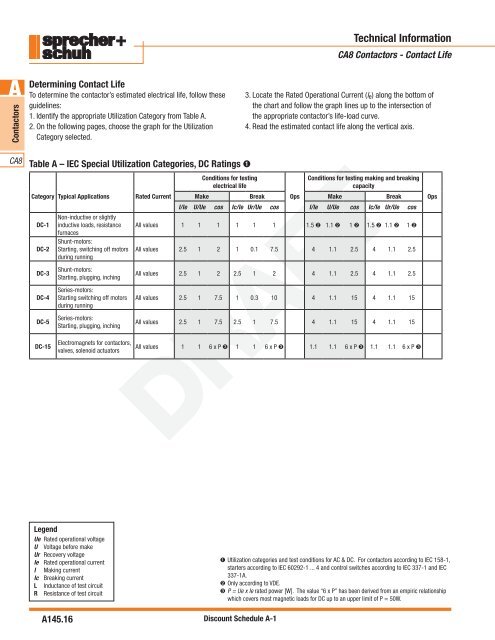
Determining Contact Life<br />
To determine the contactor’s estimated electrical life, follow these<br />
guidelines:<br />
1. Identify the appropriate Utilization Category from Table A.<br />
2. On the following pages, choose the graph for the Utilization<br />
Category selected.<br />
3. Locate the Rated Operational Current (l e ) along the bottom of<br />
the chart <strong>and</strong> follow the graph lines up to the intersection of<br />
the appropriate contactor’s life-load curve.<br />
4. Read the estimated contact life along the vertical axis.<br />
<strong>CA8</strong><br />
Table A – IEC Special Utilization Categories, DC Ratings ➊<br />
Conditions for testing<br />
electrical life<br />
Conditions for testing making <strong>and</strong> breaking<br />
capacity<br />
Category Typical Applications Rated Current Make Break Ops Make Break Ops<br />
I/Ie U/Ue cos Ic/Ie Ur/Ue cos I/Ie U/Ue cos Ic/Ie Ur/Ue cos<br />
DC-1<br />
Non-inductive or slightly<br />
inductive loads, resistance All values 1 1 1 1 1 1 1.5 ➋ 1.1 ➋ 1 ➋ 1.5 ➋ 1.1 ➋ 1 ➋<br />
furnaces<br />
Shunt-motors:<br />
DC-2 Starting, switching off motors<br />
during running<br />
All values 2.5 1 2 1 0.1 7.5 4 1.1 2.5 4 1.1 2.5<br />
DC-3<br />
DC-4<br />
DC-5<br />
DC-15<br />
Shunt-motors:<br />
Starting, plugging, inching<br />
<strong>Series</strong>-motors:<br />
Starting switching off motors<br />
during running<br />
<strong>Series</strong>-motors:<br />
Starting, plugging, inching<br />
Electromagnets for contactors,<br />
valves, solenoid actuators<br />
All values 2.5 1 2 2.5 1 2 4 1.1 2.5 4 1.1 2.5<br />
All values 2.5 1 7.5 1 0.3 10 4 1.1 15 4 1.1 15<br />
All values 2.5 1 7.5 2.5 1 7.5 4 1.1 15 4 1.1 15<br />
All values 1 1 6 x P ➌ 1 1 6 x P ➌ 1.1 1.1 6 x P ➌ 1.1 1.1 6 x P ➌<br />
DRAFT<br />
Legend<br />
Ue Rated operational voltage<br />
U Voltage before make<br />
Ur Recovery voltage<br />
Ie Rated operational current<br />
I Making current<br />
Ic Breaking current<br />
L Inductance of test circuit<br />
R Resistance of test circuit<br />
A145.16<br />
➊ Utilization categories <strong>and</strong> test conditions for AC & DC. For contactors according to IEC 158-1,<br />
starters according to IEC 60292-1 ... 4 <strong>and</strong> control switches according to IEC 337-1 <strong>and</strong> IEC<br />
337-1A.<br />
➋ Only according to VDE.<br />
➌ P = Ue x Ie rated power [W]. The value “6 x P” has been derived from an empiric relationship<br />
which covers most magnetic loads for DC up to an upper limit of P = 50W.<br />
Discount Schedule A-1