140 MHz SAW Filter 20 MHz Bandwidth Part Number ...
140 MHz SAW Filter 20 MHz Bandwidth Part Number ...
140 MHz SAW Filter 20 MHz Bandwidth Part Number ...

You also want an ePaper? Increase the reach of your titles
YUMPU automatically turns print PDFs into web optimized ePapers that Google loves.
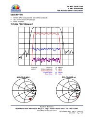
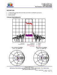
<strong>140</strong> <strong>MHz</strong> <strong>SAW</strong> <strong>Filter</strong><br />
<strong>20</strong> <strong>MHz</strong> <strong>Bandwidth</strong><br />
<strong>Part</strong> <strong>Number</strong> SF0<strong>140</strong>BA01992S<br />
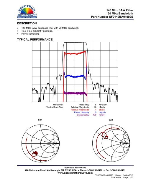
DESCRIPTION<br />
• <strong>140</strong> <strong>MHz</strong> <strong>SAW</strong> bandpass filter with <strong>20</strong> <strong>MHz</strong> bandwidth.<br />
• 13.3 x 6.5 mm SMP package.<br />
• RoHS compliant.<br />
TYPICAL PERFORMANCE<br />
Horizontal: Frequency : 8 <strong>MHz</strong>/div<br />
Vertical from Top: Relative Magnitude : 10 dB/div<br />
Relative magnitude : 1 dB/div<br />
Phase Linearity : 5 deg/div<br />
Group Delay : 100 ns/div<br />
S11<br />
S22<br />
Spectrum Microwave<br />
400 Nickerson Road, Marlborough, MA 01752, USA • Phone 1-508-251-6400 • Fax 1-508-251-6401<br />
www.SpectrumMicrowave.com<br />
DSSF0<strong>140</strong>BA01992S Rev A 5-Mar-<strong>20</strong>10<br />
ECN 36650 Page 1 of 3
<strong>140</strong> <strong>MHz</strong> <strong>SAW</strong> <strong>Filter</strong><br />
<strong>20</strong> <strong>MHz</strong> <strong>Bandwidth</strong><br />
<strong>Part</strong> <strong>Number</strong> SF0<strong>140</strong>BA01992S<br />
SPECIFICATION<br />
Parameter Min Typ Max Units<br />
Center Frequency (Fc) 1 - <strong>140</strong>.0 - <strong>MHz</strong><br />
Insertion Loss 2 - 12.7 15 dB<br />
Lower 1 dB Frequency - 129.80 130.40 <strong>MHz</strong><br />
Upper 1 dB Frequency 149.60 150.50 - <strong>MHz</strong><br />
Lower 3 dB Frequency - 129.40 130.00 <strong>MHz</strong><br />
Upper 3 dB Frequency 150.00 151.00 - <strong>MHz</strong><br />
Lower 30 dB Frequency 127.25 128.00 - <strong>MHz</strong><br />
Upper 30 dB Frequency - 152.40 152.75 <strong>MHz</strong><br />
Lower 40 dB Frequency 1<strong>20</strong>.00 121.50 - <strong>MHz</strong><br />
Upper 40 dB Frequency - 158.50 160.00 <strong>MHz</strong><br />
Passband Ripple 3 - 0.6 1.2 dB p-p<br />
Group Delay Variation 3 - 45 <strong>20</strong>0 ns p-p<br />
Absolute Delay - 1.0 1.6 us<br />
Rejection (10 to 1<strong>20</strong> <strong>MHz</strong>) 40 48 - dB<br />
Rejection (160 to 250 <strong>MHz</strong>) 40 46 - dB<br />
Source and Load Impedance - 50 - Ω<br />
Ambient Temperature (Tref) - 25 - ˚C<br />
Notes:<br />
1. Average of lower and upper 3 dB band edge frequencies.<br />
2. Measured at Fc.<br />
3. Evaluated over 139.3 to 149.7 <strong>MHz</strong>.<br />
4. Typical change of filter response with temperature is: ∆f = (T-Tref)*Tc*Fc in ppm.<br />
MAXIMUM RATINGS<br />
MATCHING CIRCUIT<br />
Parameter Min Typ Max Units<br />
Storage Temperature Range -40 25 85 ˚C<br />
Temperature Coefficient of Frequency (Tc) 4 - -94 - ppm/˚C<br />
Input Power Level - 0 10 dBm<br />
Input<br />
50 Ω<br />
Single-ended<br />
Output<br />
50 Ω<br />
Single-ended<br />
Typical component values:<br />
(Minimum inductor Q = 45)<br />
Ls1 = 68 nH Ls2 = 100 nH<br />
Notes:<br />
1. Recommend the use of + /-2% tolerance components.<br />
2. Component values shown are for guidance only and may change depending on board layout.<br />
Spectrum Microwave<br />
400 Nickerson Road, Marlborough, MA 01752, USA • Phone 1-508-251-6400 • Fax 1-508-251-6401<br />
www.SpectrumMicrowave.com<br />
DSSF0<strong>140</strong>BA01992S Rev A 5-Mar-<strong>20</strong>10<br />
ECN 36650 Page 2 of 3
<strong>140</strong> <strong>MHz</strong> <strong>SAW</strong> <strong>Filter</strong><br />
<strong>20</strong> <strong>MHz</strong> <strong>Bandwidth</strong><br />
<strong>Part</strong> <strong>Number</strong> SF0<strong>140</strong>BA01992S<br />
PACKAGE OUTLINE<br />
SUGGESTED FOOTPRINT<br />
Units: mm<br />
Tolerances are ±0.15 mm except for the<br />
overall length and width, which are<br />
nominal values.<br />
Pad Configuration:<br />
Input: 11<br />
Output: 5<br />
Ground: 1,2,3,4,6,7,8,9,10,12<br />
Package Material:<br />
Body: Al 2 O 3 ceramic<br />
Lid: Kovar, Ni plated<br />
Terminations: Au plating 1 µm min,<br />
over a 1.3-8.9 µm Ni plating<br />
ISO 9001<br />
Registered<br />
All specifications are believed to be accurate and reliable. However, Spectrum Microwave reserves the right to make changes without notice.<br />
© <strong>20</strong>10 All rights reserved.<br />
Spectrum Microwave<br />
400 Nickerson Road, Marlborough, MA 01752, USA • Phone 1-508-251-6400 • Fax 1-508-251-6401<br />
www.SpectrumMicrowave.com<br />
DSSF0<strong>140</strong>BA01992S Rev A 5-Mar-<strong>20</strong>10<br />
ECN 36650 Page 3 of 3