LCN FTW04 LCD RS485 MODBUS DE - Datenblatt EN - Thermokon ...
LCN FTW04 LCD RS485 MODBUS DE - Datenblatt EN - Thermokon ...
LCN FTW04 LCD RS485 MODBUS DE - Datenblatt EN - Thermokon ...

You also want an ePaper? Increase the reach of your titles
YUMPU automatically turns print PDFs into web optimized ePapers that Google loves.
I I I I I<br />
I I I I I<br />
I I I I I<br />
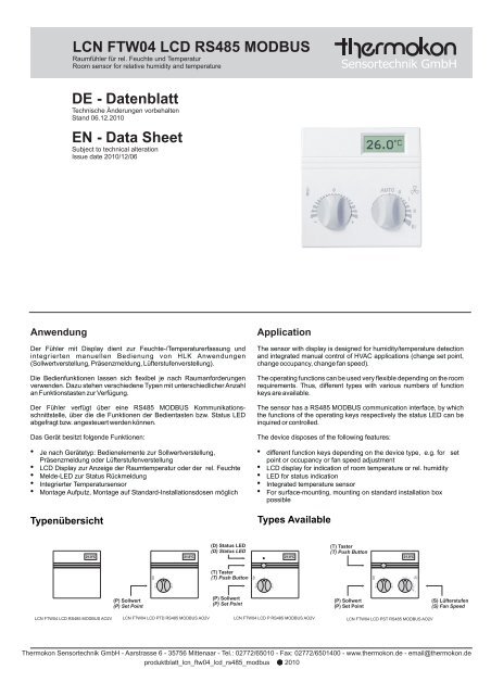
<strong>LCN</strong> <strong>FTW04</strong> <strong>LCD</strong> <strong>RS485</strong> <strong>MODBUS</strong><br />
Raumfühler für rel. Feuchte und Temperatur<br />
Room sensor for relative humidity and temperature<br />
<strong>DE</strong> - <strong>Datenblatt</strong><br />
Technische Änderungen vorbehalten<br />
Stand 06.12.2010<br />
<strong>EN</strong> - Data Sheet<br />
Subject to technical alteration<br />
Issue date 2010/12/06<br />
Anwendung<br />
Der Fühler mit Display dient zur Feuchte-/Temperaturerfassung und<br />
integrierten manuellen Bedienung von HLK Anwendungen<br />
(Sollwertverstellung, Präsenzmeldung, Lüfterstufenverstellung).<br />
Die Bedienfunktionen lassen sich flexibel je nach Raumanforderungen<br />
verwenden. Dazu stehen verschiedene Typen mit unterschiedlicher Anzahl<br />
an Funktionstasten zur Verfügung.<br />
Der Fühler verfügt über eine <strong>RS485</strong> <strong>MODBUS</strong> Kommunikationsschnittstelle,<br />
über die die Funktionen der Bedientasten bzw. Status LED<br />
abgefragt bzw. angesteuert werden können.<br />
Das Gerät besitzt folgende Funktionen:<br />
<br />
<br />
<br />
<br />
<br />
Je nach Gerätetyp: Bedienelemente zur Sollwertverstellung,<br />
Präsenzmeldung oder Lüfterstufenverstellung<br />
<strong>LCD</strong> Display zur Anzeige der Raumtemperatur oder der rel. Feuchte<br />
Melde-LED zur Status Rückmeldung<br />
Integrierter Temperatursensor<br />
Montage Aufputz, Montage auf Standard-Installationsdosen möglich<br />
Typenübersicht<br />
Application<br />
The sensor with display is designed for humidity/temperature detection<br />
and integrated manual control of HVAC applications (change set point,<br />
change occupancy, change fan speed).<br />
The operating functions can be used very flexible depending on the room<br />
requirements. Thus, different types with various numbers of function<br />
keys are available.<br />
The sensor has a <strong>RS485</strong> <strong>MODBUS</strong> communication interface, by which<br />
the functions of the operating keys respectively the status LED can be<br />
inquired or controlled.<br />
The device disposes of the following features:<br />
<br />
<br />
<br />
<br />
<br />
different function keys depending on the device type, e.g. for set<br />
point or occupancy or fan speed adjustment<br />
<strong>LCD</strong> display for indication of room temperature or rel. humidity<br />
LED for status indication<br />
Integrated temperature sensor<br />
For surface-mounting, mounting on standard installation box<br />
possible<br />
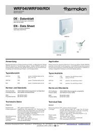
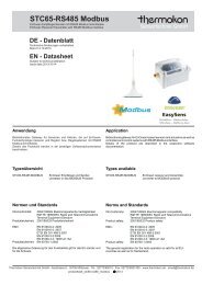
Types Available<br />
21.0°C<br />
21.0°C<br />
(D) Status LED<br />
(D) Status LED<br />
21.0°C<br />
(T) Taster<br />
(T) Push Button<br />
21.0°C<br />
0<br />
(T) Taster<br />
(T) Push Button<br />
0<br />
0<br />
AUTO 0<br />
I<br />
II<br />
-<br />
+<br />
-<br />
+<br />
-<br />
+<br />
III<br />
(P) Sollwert<br />
(P) Set Point<br />
(P) Sollwert<br />
(P) Set Point<br />
(P) Sollwert<br />
(P) Set Point<br />
(S) Lüfterstufen<br />
(S) Fan Speed<br />
<strong>LCN</strong> <strong>FTW04</strong> <strong>LCD</strong> <strong>RS485</strong> <strong>MODBUS</strong> AO2V<br />
<strong>LCN</strong> <strong>FTW04</strong> <strong>LCD</strong> PTD <strong>RS485</strong> <strong>MODBUS</strong> AO2V<br />
<strong>LCN</strong> <strong>FTW04</strong> <strong>LCD</strong> P <strong>RS485</strong> <strong>MODBUS</strong> AO2V<br />
<strong>LCN</strong> <strong>FTW04</strong> <strong>LCD</strong> PST <strong>RS485</strong> <strong>MODBUS</strong> AO2V<br />
<strong>Thermokon</strong> Sensortechnik GmbH - Aarstrasse 6 - 35756 Mittenaar - Tel.: 02772/65010 - Fax: 02772/6501400 - www.thermokon.de - email@thermokon.de<br />
produktblatt_lcn_ftw04_lcd_rs485_modbus 2010
Seite 2<br />
Page 2<br />
Typ <strong>LCN</strong> <strong>FTW04</strong> <strong>LCD</strong> <strong>MODBUS</strong> AO2V<br />
Raumfühler mit 2 analogen Ausgängen<br />
Typ <strong>LCN</strong> <strong>FTW04</strong> <strong>LCD</strong> P <strong>MODBUS</strong> AO2V<br />
Raumfühler mit Sollwert-Potentiometer (P) und 2 analogen<br />
Ausgängen<br />
Typ <strong>LCN</strong> <strong>FTW04</strong> <strong>LCD</strong> PTD <strong>MODBUS</strong> AO2V<br />
Raumfühler mit Sollwert-Potentiometer (P), Präsenztaste (T),<br />
Status-LED (D) und 2 analogen Ausgängen<br />
Typ <strong>LCN</strong> <strong>FTW04</strong> <strong>LCD</strong> PST <strong>MODBUS</strong> AO2V<br />
Sollwert-Potentiometer (P), Stufenschalter (S), Präsenztaste (T)<br />
und 2 analogen Ausgängen<br />
Type <strong>LCN</strong> <strong>FTW04</strong> <strong>LCD</strong> <strong>MODBUS</strong> AO2V<br />
room sensor with 2 analogue outputs<br />
Type <strong>LCN</strong> <strong>FTW04</strong> <strong>LCD</strong> P <strong>MODBUS</strong> AO2V<br />
room sensor with set point potentiometer (P) and 2 anlalogue<br />
outputs<br />
Type <strong>LCN</strong> <strong>FTW04</strong> <strong>LCD</strong> PTD <strong>MODBUS</strong> AO2V<br />
room sensor with set point potentiometer (P) push button (T),<br />
status LED (D) and 2 analogue outputs<br />
Type <strong>LCN</strong> <strong>FTW04</strong> <strong>LCD</strong> PST <strong>MODBUS</strong> AO2V<br />
room sensor with set point potentiometer (P), rotary switch<br />
(S), push button (T) and 2 analogue outputs<br />
Normen und Standards<br />
CE-Konformität:<br />
Produktsicherheit:<br />
2004/108/EG Elektromagnetische<br />
Verträglichkeit<br />
2001/95/EG Produktsicherheit<br />
EMV: <strong>EN</strong> 60730-1: 2002<br />
Produktsicherheit: <strong>EN</strong> 60730-1: 2002<br />
Norms and Standards<br />
CE-Conformity:<br />
Product safety:<br />
EMC: <strong>EN</strong> 60730-1: 2002<br />
Product safety: <strong>EN</strong> 60730-1: 2002<br />
2004/108/EG Electromagnetic compatibility<br />
2001/95/EG Product safety<br />
Technische Daten<br />
Allgemein:<br />
Versorgungsspannung: 15-24VDC ( 10%) oder 24VAC ( 10%)<br />
Leistungsaufnahme: typ. 0,4W / 0,6VA<br />
Messbereich:<br />
0...50°C<br />
Schnittstelle:<br />
<strong>RS485</strong>, Baudrate, Übertragungsmodus,<br />
Parität konfigurierbar (siehe<br />
Dipschaltereinstellungen) Betriebsart<br />
Halbduplex, interner Abschlusswiderstand<br />
Eingänge:<br />
2 digitale Eingänge, potentialfrei,<br />
maximale Leitungslänge 10m<br />
<strong>LCD</strong> Anzeige:<br />
29mm x 12mm, Farbe schwarz/weiß<br />
Angezeigte Funktion: rel. Feuchte oder rel. Feuchte & Temperatur<br />
(über Konfigurationsregister einstellbar)<br />
Bedienelemente: Potentiometer (P), Stufenschalter (S),<br />
Präsenztaste (T), Status LED (D)<br />
Anschlussklemme: Schraubklemme, max. 1,5mm²<br />
Gehäuse:<br />
Für Aufputzmontage, Material ASA,<br />
Farbe reinweiß, ähnlich RAL9010<br />
Schutzart:<br />
IP30 gemäß <strong>EN</strong>60529<br />
Kabeleinführung: von hinten oder seitlich oben/unten<br />
Umgebungstemperatur: -30...70°C<br />
Transport:<br />
-30...70°C / max. 85%rF, nicht kond.<br />
Gewicht:<br />
95g<br />
Technical Data<br />
General:<br />
Power supply: 15-24VDC ( 10%) or 24VAC ( 10%)<br />
Power consumption: typ. 0,4W / 0,6VA<br />
Measuring range: 0...50°C<br />
Interface:<br />
<strong>RS485</strong>, baud rate, transmission method,<br />
parity configurable (see DIP switch<br />
configuration) Mode halfduplex,internal<br />
bus terminating resistor<br />
Inputs:<br />
2 digital inputs, dry contact, max. wire<br />
length 10m<br />
<strong>LCD</strong> display: 29mm x 12mm, colour black/white<br />
Functions displayed: rel. humidity or rel. humidity & temperature<br />
(selectable via configuration register)<br />
Operating elements: Potentiometer (P), Rotary switch (S),<br />
Presence key (T), Status LED (D)<br />
Clamps:<br />
Terminal screws, max. 1,5mm²<br />
Enclosure:<br />
for wall mounting, material ASA,<br />
colour pure white, similar to RAL9010<br />
Protection:<br />
IP30 according to <strong>EN</strong>60529<br />
Cable entry:<br />
from behind or side-mounted entry from<br />
top/bottom<br />
Ambient temperature: -30...70°C<br />
Transport:<br />
-30...70°C / max. 85%rF, no condensation<br />
Weight:<br />
95g<br />
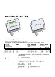
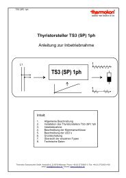
Genauigkeit<br />
Accuracy<br />
Relative Feuchte, absolute Genauigkeit<br />
Relative Humidity, absolute accuracy<br />
Temperatur, absolute Genauigkeit<br />
Temperature, absolute accuracy<br />
±6%<br />
±3°C<br />
±5%<br />
Accuracy<br />
±4%<br />
±3%<br />
±2%<br />
±1%<br />
±0%<br />
0%<br />
5%<br />
10%<br />
15%<br />
20%<br />
25%<br />
30%<br />
35%<br />
40%<br />
45%<br />
50%<br />
%RH<br />
55%<br />
60%<br />
65%<br />
70%<br />
75%<br />
80%<br />
85%<br />
90%<br />
95%<br />
100%<br />
Accuracy<br />
±2°C<br />
±1°C<br />
±0°C<br />
!<br />
Caution<br />
0°C 5°C 10°C 15°C 20°C 25°C 30°C 35°C 40°C 45°C 50°C<br />
°C<br />
<strong>Thermokon</strong> Sensortechnik GmbH - Aarstrasse 6 - 35756 Mittenaar - Tel.: 02772/65010 - Fax: 02772/6501400 - www.thermokon.de - email@thermokon.de<br />
produktblatt_lcn_ftw04_lcd_rs485_modbus 2010
Seite 3<br />
Page 3<br />
Sicherheitshinweis<br />
! SecurityAdvice !<br />
Achtung<br />
Einbau und Montage elektrischer Geräte dürfen nur durch eine<br />
Elektrofachkraft erfolgen.<br />
Caution<br />
The installation and assembly of electrical equipment may only be<br />
performed by a skilled electrician.<br />
Die Module dürfen nicht in Verbindung mit Geräten benutzt werden, die<br />
direkt oder indirekt menschlichen, gesundheits- oder lebenssichernden<br />
Zwecken dienen oder durch deren Betrieb Gefahren für Menschen, Tiere<br />
oder Sachwerte entstehen können.<br />
ElektrischerAnschluss<br />
Die Geräte sind für den Betrieb an Schutzkleinspannung (SELV) ausgelegt.<br />
Beim elektrischenAnschluss der Geräte gelten die techn. Daten der Geräte.<br />
Bei Fühlern mit Messumformer sollte dieser in der Regel in der<br />
Messbereichsmitte betrieben werden, da an den Messbereichsendpunkten<br />
erhöhte Abweichungen auftreten können. Die Umgebungstemperatur der<br />
Messumformerelektronik sollte konstant gehalten werden.<br />
Die Messumformer müssen bei einer konstanten Betriebsspannung<br />
( ±0,2V) betrieben werden. Strom-/Spannungssitzen beim Ein-/Ausschalten<br />
der Versorgungsspannung müssen bauseits vermieden werden.<br />
Montagehinweise<br />
Die Geräte werden in einem betriebsfertigen Zustand ausgeliefert. Die<br />
Montage erfolgt mittels Dübel und Schrauben (Zubehör) auf der ebenen<br />
Wandfläche. Zum Verdrahten muss das Geräteoberteil von der Grundplatte<br />
gelöst werden. Grundplatte und Oberteil sind mittels Rastnasen lösbar<br />
miteinander verbunden.<br />
Die Montage muss an repräsentativen Stellen für die Raumtemperatur<br />
erfolgen, damit das Messergebnis nicht verfälscht wird.<br />
Sonneneinstrahlung und Luftzug sind zu vermeiden. Bei Montage auf einer<br />
Standard Unterputzdose ist das Ende des Installationsrohres abzudichten,<br />
damit kein Luftzug im Rohr entsteht, der das Messergebnis verfälscht.<br />
The modules must not be used in any relation with equipment that<br />
supports, directly or indirectly, human health or life or with applications<br />
that can result in danger for people, animals or real value.<br />
Electrical Connection<br />
The devices are constructed for the operation of protective low voltage<br />
(SELV). For the electrical connection, the technical data of the<br />
corresponding device are valid.<br />
Sensing devices with transducers should in principle be operated in the<br />
middle of the measuring range to avoid deviations at the measuring end<br />
points. The ambient temperature of the transducer electronics should be<br />
kept constant.<br />
The transducers must be operated at a constant supply voltage ( ±0,2V).<br />
When switching the supply voltage on/off, power surges must be avoided<br />
on site.<br />
MountingAdvices<br />
The devices are supplied in an operational status. Installation is made by<br />
means of rawl plugs and screws (accessory) to the smooth wall surface.<br />
For wiring, the snap-on lid must be separated from the base plate.<br />
Installation must be made on representative places for the room<br />
temperature, to avoid a falsification of the measuring result. Solar<br />
radiation and draught should be avoided. If the device is mounted on<br />
standard flush box, the end of the installation tube in the flush box must<br />
be sealed, so to avoid any draught in the tube falsifying the measuring<br />
result.<br />
Grundplatte<br />
Base plate<br />
2.<br />
1.<br />
Hier Deckel öffnen<br />
Open cover here<br />
Platzierung und Genauigkeit von Raumfühlern<br />
Die Genauigkeit der Temperaturmessung ist neben einem geeigneten<br />
representativen, der Raumtemperatur entsprechenden Montageort auch<br />
direkt von der Temperaturdynamik der Wand abhängig. Wichtig ist, dass bei<br />
Unterputzfühlern die Unterputzdose zur Wand hin komplett geschlossen ist,<br />
damit eine Luftzirkulation nur durch die Öffnungen der Gehäuseabdeckung<br />
stattfinden kann. Anderenfalls kommt es zu Abweichungen bei der<br />
Temperaturmessung durch unkontrollierte Luftströmungen. Zudem sollte<br />
der Temperaturfühler nicht durch Möbel etc. abgedeckt sein. Des Weiteren<br />
sollte eine Montage in Türnähe (auftretende Zugluft) oder Fensternähe<br />
(kältereAußenwand) vermieden werden.<br />
MontageAufputz bzw. Unterputz<br />
Die Temperaturdynamik der Wand hat einen Einfluss auf das Messergebnis<br />
des Fühlers. Verschiedene Wandarten (Ziegel-, Beton, Stell-, Hohlwände)<br />
verhalten sich gegenüber Temperaturschwankungen unterschiedlich. So<br />
n i m m t e i n e m a s s i v e B e t o n w a n d v i e l l a n g s a m e r d i e<br />
Temperaturveränderung innerhalb eines Raumes wahr als Wände in<br />
Leichtbauweise. Wohnraumtemperaturfühler, die innerhalb einer UP-Dose<br />
sitzen, haben eine größere Ansprechzeit bei Temperaturschwankungen.<br />
Sie detektieren im Extremfall die Strahlungswärme der Wand, obwohl z.B.<br />
die Lufttemperatur im Raum bereits niedriger ist. Die zeitlich begrenzten<br />
Abweichungen verkleinern sich, je schneller die Dynamik der Wand ist<br />
(Temperaturannahme der Wand) oder je länger das Abfrage-Intervall des<br />
Temperaturfühlers gewählt wird.<br />
Location andAccuracy of Room Sensors<br />
Besides a suitable representative mounting place, corresponding to the<br />
room temperature, the accuracy of the temperature measurement also<br />
depends directly on the temperature dynamics of the wall. It is important,<br />
that the flush socket is completely closed at the wall side, so that the<br />
circulation of air may take place through the gaps in the cover. Otherwise,<br />
deviations in temperature measurement will occur due to uncontrolled air<br />
circulation. Furthermore, the temperature sensor should not be covered<br />
by furnitures etc.. Besides this, a mounting place next to doors (occurring<br />
draught) or windows (colder outside wall) should be avoided.<br />
Surface and Flush Mounting<br />
The temperature dynamics of the wall influence the measurement result<br />
of the sensor. Various wall types (brick, concrete, dividing and hollow<br />
brickwork) have different behaviour with regard to thermal variations. A<br />
solid concrete wall responds to thermal fluctuations within a room in a<br />
much slower way than a light-weight structure wall. Room temperature<br />
sensors installed in flush boxes, have a longer response time to thermal<br />
variations. In the extreme case, they detect the radiant heat of the wall<br />
even if for example the air temperature in the room is lower. The quicker<br />
the dynamics of the wall (temperature acceptance of the wall) or the<br />
longer the selected inquiry interval of the temperature sensor, the smaller<br />
are the deviations limited in time.<br />
<strong>Thermokon</strong> Sensortechnik GmbH - Aarstrasse 6 - 35756 Mittenaar - Tel.: 02772/65010 - Fax: 02772/6501400 - www.thermokon.de - email@thermokon.de<br />
produktblatt_lcn_ftw04_lcd_rs485_modbus 2010
Seite 4<br />
Page 4<br />
Anwenderhinweise<br />
Jegliche Berührung der empfindlichen Feuchtesensoren ist zu unterlassen<br />
und führt zum Erlöschen der Gewährleistung.<br />
Bei normalen Umgebungsbedingungen empfehlen wir ein Intervall für die<br />
Nachkalibrierung von 1 Jahr um die angegebene Genauigkeit<br />
beizubehalten.<br />
Bei hohen Umgebungstemperaturen und hohen Luftfeuchtigkeiten, sowie<br />
beim Einsatz in aggressiven Gasen kann ein vorzeitiges Nachkalibrieren<br />
oder ein Feuchtesensortausch notwendigt werden. Eine solche<br />
Nachkalibrierung oder etwaiger Sensortausch fallen nicht unter die<br />
allgemeine Gewährleistung.<br />
Wärmeentwicklung durch elektrische<br />
Verlustleistung<br />
Wohnraumtemperaturfühler mit elektronischen Bauelementen besitzen<br />
immer eine elektrische Verlustleistung, die die Temperaturmessung der<br />
Umgebungsluft beeinflusst. Die auftretende Verlustleistung in aktiven<br />
Temperaturfühlern steigt i.d.R. linear mit der steigenden Betriebsspannung.<br />
Diese Verlustleistung muß bei der Temperaturmessung berücksichtigt<br />
werden. Bei einer festen Betriebsspannung ( ±0,2V) geschieht dies in der<br />
Regel durchAddieren bzw. Subtrahieren eines konstanten Offsetwertes. Da<br />
<strong>Thermokon</strong> Messumformer mit variabler Betriebsspannung arbeiten, kann<br />
aus fertigungstechnischen Gründen nur eine Betriebsspannung<br />
berücksichtigt werden. Die Messumformer 0-10V / 4-20mA werden<br />
standardmäßig bei einer Betriebsspannung von 24VDC eingestellt, d.h. bei<br />
dieser Spannung ist der zu erwartende Messfehler des Ausgangsignals am<br />
geringsten. Bei anderen Betriebsspannungen vergrößert oder verkleinert<br />
sich der Offsetfehler aufgrund der veränderten Verlustleistung der<br />
Fühlerelektronik. Sollte beim späteren Betrieb eine Nachkalibrierung direkt<br />
am Fühler notwendig sein, so ist dies durch das auf der Fühlerplatine<br />
befindliche Trimmpoti möglich (bei Fühlern mit LON-Schnittstelle über eine<br />
entsprechende Softwarevariable SNVT). Achtung: Auftretende Zugluft führt<br />
die Verlustleistung am Fühler besser ab. Dadurch kommt es zu zeitlich<br />
begrenztenAbweichungen bei der Temperaturmessung.<br />
Application Notice<br />
Refrain from touching the sensitive humidity sensor. Any touch of the<br />
same will result in an expiration of the warranty.<br />
With normal environmental conditions we recommend a recalibration<br />
interval of around 1 year to maintain the indicated accuracy.<br />
At high ambient temperatures and high humidity, or when<br />
using the<br />
sensor in aggressive gases, an early recalibration or a change of the<br />
humidity sensor can become necessarily. Such a recalibration or a<br />
probable sensor change do not come under the general warranty.<br />
Build-up of Self-Heating by Electrical<br />
Dissipated Power<br />
Room temperature sensors with electronic components always have a<br />
dissipated power, which affects the temperature measurement of the<br />
ambient air. The dissipation in active temperature sensors shows a linear<br />
increase with rising operating voltage. This dissipated power has to be<br />
considered when measuring temperature. In case of a fixed operating<br />
voltage ( ±0,2V), this is normally be done by adding or reducing a<br />
constant offset value. As <strong>Thermokon</strong> transducers work with a variable<br />
operating voltage, only one operating voltage can be taken into<br />
consideration, for reasons of production engineering. Transducers 0-<br />
10V/4-20mA have a standard setting at an operating voltage of 24VDC.<br />
That is to say, at this voltage, the expected measuring error of the output<br />
signal will be the least.As for other operating voltages, the offset error will<br />
be increased or lowered by a changing power loss of the sensor<br />
electronics. If a re-cablibration should become necessary later directly<br />
on the sensor, this can be done by means of a trimming potentiometer on<br />
the sensor board (for sensors with LON-interface, a re-calibration can be<br />
done via corresponding software variable SNVT). Remark: Occurred<br />
draft leads to a better carrying-off of dissipated power at the sensor.<br />
Thus, temporal limited fluctuations might occur upon temperature<br />
measurement.<br />
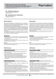
Anschlussplan (Auswahl)<br />
Terminal Connection Plan (Selection)<br />
1<br />
2<br />
3<br />
4<br />
5<br />
6<br />
7<br />
8<br />
9<br />
10<br />
11<br />
12<br />
3: Digitaler Eingang 1 / digital input 1<br />
4: Digitaler Eingang 2 / digital input 2<br />
5: GND<br />
6: Ausgang 1 heizen / output 1 heating<br />
7: Ausgang 2 kühlen / output 2 cooling<br />
8: GND<br />
9: B-<br />
10: A+<br />
11: GND<br />
12: Uv 15-24VDC / 24VAC<br />
Address<br />
1 2 3 4 5 6<br />
1 2 3 4 5 6<br />
ON<br />
Modbus<br />
options<br />
ON<br />
Geräteadresse<br />
Device Address<br />
ON<br />
1 2 3 4 5 6<br />
1<br />
off<br />
on<br />
off<br />
...<br />
2<br />
off<br />
off<br />
on<br />
...<br />
3<br />
off<br />
off<br />
off<br />
...<br />
4<br />
off<br />
off<br />
off<br />
...<br />
5<br />
off<br />
off<br />
off<br />
...<br />
6<br />
off<br />
off<br />
off<br />
...<br />
Adresse<br />
Address<br />
0 (Standard / default)<br />
1<br />
2<br />
...<br />
on<br />
on<br />
on<br />
on<br />
on<br />
on<br />
63<br />
Optionen<br />
Options<br />
ON<br />
1 2 3 4 5 6<br />
1<br />
off<br />
on<br />
Modus / Mode<br />
RTU (Standard / default)<br />
ASCI<br />
2<br />
off<br />
on<br />
off<br />
on<br />
3<br />
off<br />
off<br />
on<br />
on<br />
Baud<br />
9600<br />
19200<br />
38400<br />
57600<br />
(Standard / default)<br />
4<br />
on<br />
off<br />
off<br />
5<br />
off<br />
on<br />
off<br />
Parität / Parity<br />
even (Standard / default)<br />
odd<br />
no<br />
6<br />
off<br />
on<br />
Abschluss / Termination<br />
inaktiv (Standard / default)<br />
120Ohm<br />
Zubehör optional<br />
Optional Accessories<br />
(D+S)<br />
1 Satz (je 2 Stück) Dübel und Schrauben<br />
(D+S) 1 Set (2 pieces each) rawl plugs and screws<br />
<strong>Thermokon</strong> Sensortechnik GmbH - Aarstrasse 6 - 35756 Mittenaar - Tel.: 02772/65010 - Fax: 02772/6501400 - www.thermokon.de - email@thermokon.de<br />
produktblatt_lcn_ftw04_lcd_rs485_modbus 2010
Seite 5<br />
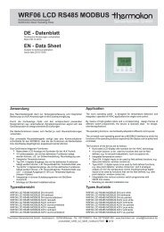
Abmessungen (mm)<br />
Page 5<br />
Dimensions (mm)<br />
21.0°C<br />
I I I I I<br />
0<br />
AUTO 0<br />
I<br />
-<br />
+<br />
II<br />
III<br />
<strong>Thermokon</strong> Sensortechnik GmbH - Aarstrasse 6 - 35756 Mittenaar - Tel.: 02772/65010 - Fax: 02772/6501400 - www.thermokon.de - email@thermokon.de<br />
produktblatt_lcn_ftw04_lcd_rs485_modbus 2010