HPHS Mechanical, Electrical, Plumbing and Fire Protection Building ...
HPHS Mechanical, Electrical, Plumbing and Fire Protection Building ...
HPHS Mechanical, Electrical, Plumbing and Fire Protection Building ...

Create successful ePaper yourself
Turn your PDF publications into a flip-book with our unique Google optimized e-Paper software.
MECHANICAL, ELECTRICAL,<br />
PLUMBING & FIRE PROTECTION<br />
BUILDING EVALUATION<br />
At:<br />
Highl<strong>and</strong> Park High School<br />
433 Vine Avenue<br />
Highl<strong>and</strong> Park, Illinois 60035<br />
For:<br />
Township High School District 113<br />
1040 Park Avenue West<br />
Highl<strong>and</strong> Park, Illinois 60035-2257<br />
August 2010 – January 2011<br />
Prepared by:<br />
Metro Design Associates, Inc.<br />
1707 R<strong>and</strong>all Road, Suite 390<br />
Elgin, Illinois 60123<br />
Ph: 224-629-4444<br />
F: 847-622-7485<br />
Website: www.metrodgn.com
Introduction:<br />
Wight & Company commissioned Metro Design Associates to perform a mechanical,<br />
electrical, plumbing <strong>and</strong> fire protection evaluation of the existing systems currently<br />
serving Highl<strong>and</strong> Park High School. The evaluation consisted of numerous site visits to<br />
document existing conditions as well as interviews with key personnel at the school <strong>and</strong><br />
review of available construction documents. The direction received was to evaluate the<br />
current equipment <strong>and</strong> systems, document the type, size, location <strong>and</strong> their condition<br />
<strong>and</strong> provide a justification for any recommendations for replacement.<br />
Any recommended systems replacements proposed in this report were selected on<br />
several criteria. First, meet all heating, ventilating, air conditioning <strong>and</strong> life safety current<br />
code st<strong>and</strong>ards for ventilation. In addition, all systems indicated to be replaced. Meet the<br />
Illinois Energy Code st<strong>and</strong>ards to provide the most favorable energy efficient systems<br />
possible so that District 113 can reap the benefits of the energy use savings for years to<br />
come. Another major factor was “mean life expectancy” of equipment. Obviously exterior<br />
mounted equipment has a much shorter useful life than indoor equipment. The<br />
justification was to propose equipment that will utilize the current indoor mechanical<br />
spaces available <strong>and</strong> provide a thirty to thirty-five year life expectancy for the systems.<br />
The following is a detailed account of the equipment <strong>and</strong> systems currently in place <strong>and</strong><br />
in operation at the school as well as recommendations of proposed system<br />
replacements for the buildings <strong>and</strong> spaces as they are used at the time this study took<br />
place.<br />
Note:<br />
As a long-range capital facilities <strong>and</strong> technology plan is developed <strong>and</strong> phased, the<br />
scope of work recommended here will need to be modified <strong>and</strong> updated to be aligned<br />
with updated phases <strong>and</strong> repurposing of spaces. At the end of this study, a brief<br />
description of HVAC systems within the new construction areas has been added.<br />
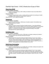
Main A West<br />
Current System Installed:<br />
<br />
HVAC Infrastructure Scope of Work<br />
Space is currently served by one (1), 1967, (3) zone multi-zone unit serving the<br />
Auditorium classrooms on the 3 rd floor. A Trane gas fired rooftop unit installed in<br />
1996 serves the staff office 333. And new chilled water cooling / hot water<br />
heating unit serves the 1 st <strong>and</strong> 2 nd floor <strong>and</strong> was installed under the 2001<br />
renovation. Due to age, condition <strong>and</strong> lack of energy efficiency the<br />
recommendation would be to replace this system with new.<br />
Scope of Work:<br />
<br />
Replace existing 3-zone multi zone unit from 1967 original construction serving<br />
the Auditorium classrooms on the 3 rd floor. Provide a new VAV indoor air h<strong>and</strong>ler<br />
in same location utilizing hot water heat <strong>and</strong> chilled water cooling.
The 1996 Trane gas fired constant volume rooftop unit should be removed <strong>and</strong><br />
this space served from the new VAV h<strong>and</strong>ler indicated above.<br />
Each individual space would utilize a fan powered VAV box with a hot water<br />
reheat coil to provide individual room control. This proposed system will save<br />
energy over the current system installed.<br />
“A” <strong>Building</strong><br />
Current System Installed:<br />
<br />
<br />
<br />
<br />
Two (2), 1957, heating only air h<strong>and</strong>lers serve the majority of the A wing of the<br />
building. Each unit is constant volume <strong>and</strong> have return air fans. Due to age,<br />
condition <strong>and</strong> lack of energy efficiency the recommendation would be to replace<br />
this system with new.<br />
A Trane VAV air h<strong>and</strong>ler with chilled water cooling <strong>and</strong> hot water heating serves<br />
the Media Center from room A120 to A112A <strong>and</strong> was installed in 2001.<br />
A Trane cooling only indoor air h<strong>and</strong>ler serves the Staff dining Room A106. This<br />
constant volume unit was installed under the 2001 renovation. This system is<br />
only capable of providing air conditioning during the cooling season <strong>and</strong> has no<br />
ability to heat.<br />
Two Lennox, cooling only, rooftop units (6 & 15 tons) are installed on the roof<br />
above the main lobby <strong>and</strong> serve Rooms A311, A313 & A315. The units are<br />
constant volume. These systems are only capable of providing air conditioning<br />
during the cooling season <strong>and</strong> have no ability to heat. Units are at their mean life<br />
expectancy <strong>and</strong> should be considered for replacement.<br />
Scope of Work:<br />
<br />
<br />
<br />
<br />
The Staff Dining Room air h<strong>and</strong>ler should remain in place. A hot water heating<br />
coil <strong>and</strong> related piping should be added to allow the unit to serve the space year<br />
round <strong>and</strong> provide year round ventilation. If the staff dining room is relocated to<br />
the area of the current cafeteria <strong>and</strong> the existing space is repurposed as a<br />
classroom, the existing air h<strong>and</strong>ler could either remain <strong>and</strong> serve the new space<br />
or the new space could be incorporated into a new main system serving building<br />
A.<br />
The Trane VAV air h<strong>and</strong>ler serving the Media Center, installed in 2001, should<br />
remain as is without modification.<br />
The two Lennox, cooling only, rooftop units serving Rooms A311, A313 & A315<br />
should be replaced with similar equipment of the same size. The existing<br />
ductwork would remain <strong>and</strong> be re-used. The new units should include gas-fired<br />
heating to allow for year round use <strong>and</strong> ventilating.<br />
The two 1957 heating only air h<strong>and</strong>lers serving the A wing of the building should<br />
be replaced in their entirety including all related ductwork. Two (2) new indoor<br />
VAV air h<strong>and</strong>lers should be installed in the same location as the existing. Each<br />
unit would have hot water heating, chilled water cooling <strong>and</strong> return air fans. Each<br />
space served by these two units would be provided with individual room control<br />
via fan powered VAV boxes with hot water reheat.<br />
“B” <strong>Building</strong><br />
Current System Installed:<br />
<br />
This building was renovated under the 2001 renovation project <strong>and</strong> all<br />
classrooms are served by floor mounted four pipe chilled / hot water unit<br />
ventilators. Problems have been persistent with these units from the start with
coils freezing due to the chilled water coil being installed on the entering air side<br />
of the hot water coil. The district has to drain down the chilled coils every year to<br />
prevent coil freezing.<br />
One chilled water cooling / hot water heating constant volume air h<strong>and</strong>ler is<br />
installed in the center mechanical room on the 2 nd floor <strong>and</strong> serves the corridor.<br />
This unit was installed during the 2001 renovation<br />
Two separate pressurization relief systems, one serving the 3 rd <strong>and</strong> 4 th floor <strong>and</strong><br />
one the 1 st <strong>and</strong> 2 nd floor serve to relieve building pressurization as the buildings<br />
unit ventilator system operates in economizer mode. They are installed in the<br />
attic <strong>and</strong> the 2 nd floor mechanical rooms. These systems were installed under the<br />
2001 renovation project.<br />
Scope of Work:<br />
<br />
<br />
Install a plate <strong>and</strong> frame heat exchanger in the chilled water system that will<br />
allow the secondary loop to be 30% ethylene glycol. That will allow the chilled<br />
water to remain in the system year round <strong>and</strong> prevent coil freezing.<br />
Note:<br />
The system installed with this portion of the school appears to be a B<strong>and</strong>-Aid to a<br />
more serious infrastructure problem. Due to the building age <strong>and</strong> construction,<br />
HVAC options where limited, using unit ventilators where one of only a few<br />
available options that could be used. Unit ventilators have inherent problems<br />
such as potential coil freezing, lack of proper air distribution, poor pressurization<br />
controls.<br />
In addition the sanitary <strong>and</strong> storm piping serving the building is 100 years old.<br />
Based on age of the piping, both sanitary <strong>and</strong> storm may be significantly<br />
deteriorated, as staff report persistent back-ups <strong>and</strong> flooding. As-buit plans are<br />
not available to record where actual connections to municipal services are<br />
located or the routing of the actual underground within the building.<br />
The cost associated with full replacement of all MEP systems would be more<br />
costly within this building than the cost of a new system serving a new building<br />
simply because of the demolition cost associated with accessing the existing<br />
system. Therefore, an additional recommendation would be replacement of the<br />
facility in total.<br />
Auditorium<br />
Current System Installed:<br />
<br />
An air h<strong>and</strong>ler system, installed in 2001, is located in the mechanical room G200<br />
on the Science wing <strong>and</strong> serves the Auditorium. The unit is a constant volume<br />
unit with chilled water <strong>and</strong> hot water coils <strong>and</strong> a return air fan.<br />
Scope of Work:<br />
The existing air h<strong>and</strong>ler should remain without modification.<br />
Science Wing<br />
Current System Installed:<br />
<br />
A variable air volume (VAV) air h<strong>and</strong>ler system, installed in 2001, is located in<br />
the basement mechanical room G117 on the Science wing <strong>and</strong> serves the entire<br />
new addition. The unit has a chilled water cooling coil <strong>and</strong> hot water heating coils<br />
with a return air fan.
Scope of Work:<br />
The existing air h<strong>and</strong>ler should remain without modification.<br />
Studio Theatre<br />
Current System Installed:<br />
<br />
An air h<strong>and</strong>ler system, installed in 2001, located on the mezzanine of the boiler<br />
room serves this portion of the building. The unit is constant air volume with<br />
direct expansion cooling, steam heating coil <strong>and</strong> no return air fan. The air cooled<br />
condenser is located on the roof above the air h<strong>and</strong>ler.<br />
Scope of Work:<br />
<br />
Replace the DX coil with a chilled water coil. Remove the existing air cooled<br />
condenser <strong>and</strong> serve the cooling coil from the chilled water system. Add a return<br />
fan to allow for full economizer control (free cooling). These modifications will<br />
increase the current systems efficiency.<br />
B<strong>and</strong> / Choir<br />
Current System Installed:<br />
Each of the large assembly areas are served by individual 5 ton gas-fired<br />
packaged rooftop units. The units were installed in 1995 <strong>and</strong> are in need of<br />
replacement. The units are undersized to meet the cooling <strong>and</strong> ventilation needs<br />
of these spaces.<br />
In a mechanical penthouse located above the B<strong>and</strong> <strong>and</strong> Choir rooms are four (4)<br />
steam, heating only, air h<strong>and</strong>lers that once served the practice rooms <strong>and</strong> related<br />
offices in the B<strong>and</strong> area. These units have not operated in many years <strong>and</strong> have<br />
been left ab<strong>and</strong>oned in place. The spaces once served by these units are<br />
currently only served by perimeter fin tube radiation <strong>and</strong> no means of mechanical<br />
or natural ventilation exist in this area. This is a violation of the International<br />
<strong>Mechanical</strong> code.<br />
Scope of Work:<br />
<br />
Remove all existing systems <strong>and</strong> install a new indoor VAV air h<strong>and</strong>ler in the<br />
existing penthouse located above the B<strong>and</strong> area. The unit shall have hot water<br />
heating, chilled water cooling <strong>and</strong> a return air fan. Each space served shall be<br />
provided with individual room control via fan powered VAV boxes with hot water<br />
reheat.<br />
“C” Annex <strong>Building</strong> - Art<br />
Current System Installed:<br />
<br />
A Trane rooftop air h<strong>and</strong>ler with hot water heating serves the “C” Annex building.<br />
The unit is VAV <strong>and</strong> provides individual room control. It was installed in 2001.<br />
Scope of Work:<br />
<br />
<br />
Add a chilled water cooling coil to the existing air h<strong>and</strong>ler including all related<br />
piping <strong>and</strong> controls.<br />
Convert the 2001 hot water variable air volume (VAV) boxes to fan powered VAV<br />
boxes. This will allow for better temperature <strong>and</strong> ventilation control in the summer<br />
when the boilers are non-operational.
“C” <strong>Building</strong> - Wrestling <strong>and</strong> Gymnastics Gymnasium<br />
Current System Installed:<br />
<br />
<br />
<br />
<br />
A 1940 air h<strong>and</strong>ler, located in the basement under the Technology area, serves<br />
both the Wrestling <strong>and</strong> Gymnastics Gymnasium. The unit is heating only utilizing<br />
a steam heating coil. No return fan was observed. The airflow to both<br />
Gymnasiums is minimal <strong>and</strong> our assumption is that the unit does not meet the<br />
code required ventilation for both gymnasiums.<br />
The supply air provided to the gymnasiums was intended to be relieved by<br />
exhaust fans located on the mezzanine of the gymnastics gymnasium. These<br />
fans have been out of service for some time <strong>and</strong> have been left ab<strong>and</strong>oned in<br />
place.<br />
Supplemental heat to these spaces is by steam cast iron radiators dating back to<br />
the original construction of the building. These radiators can become very hot to<br />
the touch <strong>and</strong> pose a safety risk to the users of the space.<br />
Perimeter spaces on either side of these gyms have no means of ventilation, only<br />
radiators to provide heating.<br />
Scope of Work:<br />
<br />
<br />
Install two (2) constant volume air h<strong>and</strong>lers located on the upper floor<br />
mezzanines. One unit to serve wrestling <strong>and</strong> one to serve the gymnasium. Each<br />
unit should have chilled water cooling <strong>and</strong> hot water heating. These units should<br />
also serve the perimeter spaces on each floor. This modification will provide the<br />
required ventilation to meet current code st<strong>and</strong>ards as well increase the overall<br />
efficiency saving operational <strong>and</strong> maintenance dollars. All existing equipment<br />
would be removed.<br />
These Gymnasiums currently have no toilet or drinking water facilities since no<br />
domestic water or sanitary sewer systems are operational in the “C” building.<br />
Technology Lab: (lower level of 1914 “C” <strong>Building</strong><br />
Gymnasium)<br />
Current System Installed:<br />
<br />
Located on the roof, just west of the 1914 gym building, the Trane rooftop air<br />
h<strong>and</strong>ler was installed under the 2001 renovation project. The unit has hot water<br />
heating <strong>and</strong> chilled water cooling. The system is VAV <strong>and</strong> provides individual<br />
room control.<br />
Scope of Work:<br />
<br />
<br />
Library<br />
Existing air h<strong>and</strong>ler shall remain without modification.<br />
Convert the 2001 hot water variable air volume (VAV) boxes to fan powered VAV<br />
boxes. This will allow for better temperature <strong>and</strong> ventilation control in the summer<br />
time when the boilers are non-operational.<br />
Current System Installed:<br />
<br />
A 1967 multi-zone air h<strong>and</strong>ling unit with 11 zones serves the Library. The unit<br />
has a direct expansion cooling coil <strong>and</strong> a steam heating coil. The unit has a<br />
separate in-line return fan associated with the system. Due to age, condition <strong>and</strong><br />
lack of energy efficiency the recommendation would be to replace this system<br />
with new.
A roof mounted Trane air cooled condenser located above the library serves the<br />
multi-zone unit. This unit was installed around 1996. Direct expansion cooling is<br />
less efficient than chilled water. Under the unit replacement, remove the<br />
condensing unit <strong>and</strong> install a chilled water cooling coil.<br />
Scope of Work:<br />
<br />
Replace the existing 11-zone multi zone unit from 1967 original construction<br />
serving the Library. Provide a new VAV indoor air h<strong>and</strong>ler in the same location<br />
utilizing hot water heat <strong>and</strong> chilled water cooling. Each space served by this unit<br />
shall be provided with individual room control via fan powered VAV box with hot<br />
water reheat.<br />
Cafeteria / Kitchen / Student Commons<br />
Current System Installed:<br />
<br />
<br />
<br />
<br />
<br />
<br />
Located in the basement below the kitchen are two (2) 100% outside air airh<strong>and</strong>lers<br />
that serve the cafeteria <strong>and</strong> kitchen as well as make up to the kitchen<br />
hoods. Each unit has a filter section, face <strong>and</strong> bypass dampers <strong>and</strong> steam<br />
heating coil. Units appear to be 50+ years old.<br />
Each branch off the supply ductwork from these units is equipped with a steam<br />
reheat coil for individual space temperature control.<br />
In addition to these units are two additional small air h<strong>and</strong>lers located in the<br />
ceiling space above the corridor between the cafeteria <strong>and</strong> exhibition gym. The<br />
units are heating only, <strong>and</strong> only one unit is currently in operation. The loss of<br />
supply <strong>and</strong> outside airflow from the unit that is non-operational reduces the<br />
amount of code required ventilation air to below code requirements.<br />
For airflow not exhausted by the kitchen hood, a separate utility exhaust fan is<br />
located in the tunnel <strong>and</strong> is ducted to the south side of the cafeteria. The fan is of<br />
1940’s vintage <strong>and</strong> in poor condition.<br />
Under the 2001 renovation, a steam to hot water heat exchanger was installed to<br />
create heating hot water to serve new HVAC equipment within this area of the<br />
building.<br />
The bookstore, which is now part of the cafeteria, was partitioned off at some<br />
point. This space is served by the systems indicated above. No individual room<br />
control exists <strong>and</strong> the space is receiving100% outside air, which is not required,<br />
<strong>and</strong> therefore, using more energy than required.<br />
Due to age, condition <strong>and</strong> inefficiency, these systems serving the Cafeteria /<br />
Kitchen / Student Commons should be replaced. New equipment will increase<br />
the energy saved over the current system two-fold.<br />
Scope of Work:<br />
<br />
<br />
<br />
Replace the current units with one (1) rooftop or indoor air h<strong>and</strong>ler, constant<br />
volume with chilled water cooling <strong>and</strong> hot water heating. Spiral round supply air<br />
ductwork could be exposed or rectangular, if concealed, distributed throughout<br />
the space with return airflow in the space.<br />
A 100% outside air make-up air unit would be installed to serve the kitchen hood.<br />
Spot cooling of the kitchen would be from the cafeteria unit. A separate zone<br />
would serve the kitchen. The remainder of make-up air for the hood shall come<br />
from the cafeteria.
2001 Athletic Entrance Lobby<br />
Current System Installed:<br />
<br />
The 2001 Athletic Entrance lobby addition is served by a hot water heating only<br />
rooftop air h<strong>and</strong>ler installed under to the 2001 renovation project. No cooling was<br />
provided. Due to the large amount of glass in this space, the heat gain in the<br />
summer is significant <strong>and</strong> cooling should be provided to the unit as this area is<br />
used by students for various activities throughout the school day as an extension<br />
of the cafeteria/commons area.<br />
Scope of Work:<br />
<br />
Add a chilled water cooling coil to the existing rooftop air h<strong>and</strong>lers including all<br />
related piping <strong>and</strong> controls.<br />
Climbing Wall / Meeting Room<br />
Current System Installed:<br />
<br />
This space has no heating or ventilation. The cabinet unit heater that once<br />
serving the space has been disconnected <strong>and</strong> left ab<strong>and</strong>oned. This is in violation<br />
of code.<br />
Scope of Work:<br />
<br />
Install a gas-fired, heating/cooling constant volume packaged rooftop unit<br />
dedicated to serve this room.<br />
Exhibition Gym<br />
Current System Installed:<br />
<br />
Two (2) air h<strong>and</strong>ler systems, installed in 2001, are located on the roof of the<br />
exhibition gym <strong>and</strong> serve this portion of the building. The units are constant air<br />
volume with hot water heating only. Distribution ductwork in the gym utilizes duct<br />
sock for supply air <strong>and</strong> sheet metal for return air. Due to the low velocity supply<br />
air delivered by the “duct sock” <strong>and</strong> the high elevation of the return air ductwork<br />
the systems are short cycling <strong>and</strong> not satisfying the space temperature needs.<br />
Scope of Work:<br />
<br />
<br />
Add a chilled water cooling coil to the two existing air h<strong>and</strong>lers including all<br />
related piping <strong>and</strong> controls.<br />
Modify the return air ductwork so that the return air is at the floor level of the gym<br />
(instead of the ceiling level).<br />
Intramural Gym<br />
Current System Installed:<br />
<br />
Two (2) air h<strong>and</strong>ler systems, installed in 2001, are located on the roof of the<br />
intramural gym <strong>and</strong> serve this portion of the building. The units are constant air<br />
volume with hot water heating only. Distribution ductwork in the gym utilizes duct<br />
sock for supply air <strong>and</strong> sheet metal for return air. The same “short cycling” <strong>and</strong><br />
temperature control problems are being experienced as in the Exhibition Gym.<br />
The units may have been reported to be equipped with a chilled water-cooling<br />
coil that was not piped under the 2001 renovation. This will need to be verified.<br />
Scope of Work:<br />
<br />
Add a chilled water cooling coil to the two existing air h<strong>and</strong>lers including all<br />
related piping <strong>and</strong> controls.
Modify the return air ductwork so that the return is at the floor level of the gym<br />
instead of the ceiling line.<br />
Boys Locker Room<br />
Current System Installed:<br />
<br />
One rooftop air h<strong>and</strong>ler system, installed in 2001, is located on the roof of the<br />
intramural gym serves this portion of the building. The unit is constant air volume<br />
with hot water heating only. Distribution ductwork utilizes duct sock for supply air<br />
<strong>and</strong> sheet metal for return air.<br />
Scope of Work:<br />
<br />
Add a chilled water cooling coil to the two existing air h<strong>and</strong>lers including all<br />
related piping <strong>and</strong> controls.<br />
Indoor Track / PE Classrooms / Fitness Room (Basement<br />
level below Locker rooms)<br />
Current System Installed:<br />
<br />
<br />
One rooftop air h<strong>and</strong>ler system, installed in 2001, is located on the roof of the<br />
Exhibition Gym mezzanine rooms <strong>and</strong> serves this portion of the building. The unit<br />
is constant air volume with hot water heating only. Distribution ductwork utilizes<br />
duct sock for supply air <strong>and</strong> sheet metal for return air.<br />
The individual rooms located in the space are served off the same system as the<br />
track area. No individual room control exists <strong>and</strong> return air grilles are not<br />
provided.<br />
Scope of Work:<br />
<br />
<br />
<br />
Pool<br />
Add a chilled water cooling coil to the existing air h<strong>and</strong>ler including all related<br />
piping <strong>and</strong> controls.<br />
Increase the motor HP to allow for additional static pressure. Currently the air<br />
h<strong>and</strong>ler does not have sufficient air pressure to totally inflate the duct sock.<br />
Provide separate reheat coils for each space served to provide individual room<br />
control. Change the units control sequence to control discharge air. Include<br />
means of return air from the individual spaces back to the air h<strong>and</strong>ler<br />
Current System Installed:<br />
<br />
One rooftop dehumidification air h<strong>and</strong>ler system manufactured by Desert Air was<br />
installed in 2006 <strong>and</strong> is located on the roof of the pool. The unit is constant air<br />
volume with hot water heating <strong>and</strong> direct expansion cooling. Distribution<br />
ductwork utilizes duct sock for supply air <strong>and</strong> sheet metal for return air.<br />
Scope of Work:<br />
<br />
Existing air h<strong>and</strong>ler should remain without modification. If a new pool is proposed<br />
the existing unit has the ability to be re-used under the new design. Depending<br />
on the space size <strong>and</strong> occupancy a supplemental unit may be required.<br />
Girls Locker Room<br />
Current System Installed:<br />
<br />
One indoor air h<strong>and</strong>ler system, installed in 2001, is located in the lower level<br />
mechanical room below the girl’s locker room <strong>and</strong> serves this portion of the
uilding. The unit is constant air volume with hot water heating only. Distribution<br />
ductwork utilizes duct sock for supply air <strong>and</strong> sheet metal for return air.<br />
Scope of Work:<br />
<br />
Add a chilled water cooling coil to the existing air h<strong>and</strong>ler including all related<br />
piping <strong>and</strong> controls.<br />
PE Offices<br />
Current System Installed:<br />
<br />
These spaces are located on the south side of the boy’s locker room <strong>and</strong> have<br />
no mechanical ventilation. Fin tube radiation exists for heating only. The spaces<br />
are on an exterior wall <strong>and</strong> may meet the natural ventilation requirements of the<br />
original school code in which the building was constructed under.<br />
Scope of Work:<br />
<br />
Install an individual chilled water cooling <strong>and</strong> hot water heating fan coil unit in<br />
each space. Each unit will have a dedicated outside air connection to meet the<br />
mechanical ventilation requirements.<br />
S<strong>and</strong>wick Hall<br />
Current System Installed:<br />
<br />
<br />
The North portion of S<strong>and</strong>wick hall is served by a VAV air h<strong>and</strong>ler located in the<br />
lower level mechanical room off the boiler room. The unit has chilled water <strong>and</strong><br />
hot water heating coils <strong>and</strong> was installed under the 2001 renovation project.<br />
The space above the buildings <strong>and</strong> grounds office is served by this unit but has<br />
poor ventilation. The space lacks sufficient air flow.<br />
Scope of Work:<br />
<br />
<br />
Convert the 2001 hot water variable air volume (VAV) boxes to fan powered VAV<br />
boxes. This will allow for better temperature <strong>and</strong> ventilation control in the summer<br />
time when boilers are non-operational.<br />
Modify the current ductwork to add control to serve the space above the buildings<br />
<strong>and</strong> grounds office.<br />
S<strong>and</strong>wick Hall /Music “E” Wing<br />
Current System Installed:<br />
<br />
The north portion of S<strong>and</strong>wick Hall <strong>and</strong> east portion of the Music E Wing is<br />
served by a rooftop air h<strong>and</strong>ling unit manufactured by Trane <strong>and</strong> installed in 2001<br />
under the renovation project. The unit is VAV with chilled water-cooling <strong>and</strong> hot<br />
water heating.<br />
Scope of Work:<br />
<br />
<br />
Add a return fan to the air h<strong>and</strong>ler system to allow for full economizer control.<br />
Convert the 2001 hot water variable air volume (VAV) boxes to fan powered VAV<br />
boxes. This will allow for better temperature <strong>and</strong> ventilation control in the summer<br />
time when boilers are non-operational.<br />
Boiler Room<br />
Current System Installed:<br />
<br />
The boiler room equipment was replaced in its entirety under the 2001 renovation<br />
project. This included the following:
(2) Burnham steam boilers<br />
4 chilled water pumps<br />
Feedwater system<br />
Condensate return system<br />
Water softener<br />
(2) Hot water pumps<br />
(1) Steam to hot water heat exchanger<br />
(2) 250 ton air cooled Trane Chillers<br />
Scope of Work:<br />
<br />
The existing boilers should be converted from steam to hot water. This will<br />
increase the system’s operating/energy efficiency <strong>and</strong> lessen maintenance.<br />
Since all steam equipment is being replaced or upgraded, this is the best option<br />
for the future of the facility. The feed water condensate pumps <strong>and</strong> steam to<br />
water heat exchanger would be removed. Additional chiller capacity will need to<br />
be added to support the air h<strong>and</strong>lers utilizing chilled water under the renovation.<br />
Assume an additional 600 tons of air cooled chiller will be installed. This will<br />
require additional pumping capacity as well as the main chilled water lines will<br />
need to be supplemented through the building to carry the additional cooling<br />
capacity. Chilled water cooling is the most efficient means of providing air<br />
conditioning over a conventional individual direct expansion system.<br />
Chiller Upgrade<br />
<br />
Additional chiller capacity will need to be added to support the new <strong>and</strong> existing<br />
air h<strong>and</strong>lers utilizing chilled water under the recommended changes. We have<br />
assumed an additional 600 tons of chiller would be installed. The location of the<br />
chilled water plant will need to be determined, but based on recent<br />
conversations, the best location may be adjacent to the existing chillers outside<br />
the boiler room. The chillers will be air or water cooled. All pumping will be<br />
located in the boiler room. New chilled water piping will need to be distributed<br />
throughout the building. The chiller efficiency will vary greatly depending on the<br />
type selected but an assumption can be made that the efficiency will be below 1<br />
KW / ton which will far exceed the efficiency of packaged equipment or air cooled<br />
condensers.<br />
Terminal Heat Transfer Units<br />
Current System Installed:<br />
<br />
A majority of the terminal equipment such as convectors, cabinet heaters,<br />
suspended heaters; fin tube radiation <strong>and</strong> cast iron radiators are original to the<br />
construction of the building <strong>and</strong> were not replaced under the 2001 renovation<br />
project. Consideration should be given to replace this equipment under future<br />
renovations projects.<br />
Scope of Work:<br />
<br />
Consideration should be given to replace all existing steam terminal equipment in<br />
the building older than the 2001 renovation due to age <strong>and</strong> condition.<br />
Exhaust Fans<br />
<br />
Approximately 1/2 of the exhaust fans serving the building are original to the<br />
construction of the building <strong>and</strong> were not replaced under the 2001 renovation
project. Older fans have a tendency to lose capacity due to belt slippage, duct<br />
leakage, <strong>and</strong> housing loses. The actual amount of air being exhausted in most<br />
cases will be less than the design or current code st<strong>and</strong>ards due to the code the<br />
building was constructed under did not have as stringent ventilation capacities as<br />
current codes.<br />
Scope of Work:<br />
<br />
All existing exhaust fans older than the 2001 renovations are recommended for<br />
replacement with new fans capable of meeting current code st<strong>and</strong>ards. A further,<br />
more detailed evaluation will need to take place to determine the exact location,<br />
size <strong>and</strong> quantity of fans required to be replaced, as many fans are not readily<br />
accessible.<br />
<strong>Electrical</strong> Infrastructure Work<br />
Current System Installed:<br />
<br />
<br />
Under the 2001 renovation a new 3200 amp, 3 phase, 4 wire 480/277 Volt<br />
electrical service was installed to support the new additions <strong>and</strong> HVAC<br />
equipment. There remains a lack of circuit space for future <strong>and</strong> current electrical<br />
loads. Past <strong>and</strong> anticipated future expansion of technology has exceeded the<br />
capacity of the distribution panels throughout all of the classroom <strong>and</strong><br />
instructional areas. Future renovation <strong>and</strong> expansion projects should include<br />
additional distribution panels located throughout the building. Classrooms,<br />
administrative areas <strong>and</strong> common spaces all need additional electrical outlets to<br />
accommodate the growing need for technology device use.<br />
Lighting has been upgraded over the years by retrofitting ballasts <strong>and</strong> lamps<br />
inside the original fixtures, however a majority of the original fixtures still remain.<br />
Older fixtures do not distribute or diffuse the light levels to the quality of today’s<br />
recommendations for learning environments, Upgraded lighting <strong>and</strong> lighting<br />
levels to current st<strong>and</strong>ards for schools is recommended. In addition, occupancy<br />
sensors are required to be added to meet current Illinois Energy Codes<br />
St<strong>and</strong>ards in renovated <strong>and</strong> new areas.<br />
Scope of Work:<br />
<br />
<br />
Due to the increase in cooling capacity, <strong>and</strong> increase in the electrical service to<br />
the building to support the increased chiller capacity will be required. This<br />
increase in electrical capacity would also be sized to accommodate future<br />
increases in technology throughout the entire facility. Additional capacity could<br />
fall in the range of 1500 to 2000 amps at 480 volt 3 phase.<br />
Replace the lighting throughout the building in all locations not associated with<br />
the 2001 project with fixtures upgraded to T-5 or T-8 lamps Replace all exit signs,<br />
with L.E.D. lamps <strong>and</strong> replace the emergency lighting systems to have the<br />
required backup capabilities or to be connected to an emergency generator.<br />
Existing EM or exit lighting does not meet current code st<strong>and</strong>ards for lighting<br />
illumination, energy efficiency or back up capabilities, therefore, replacement is<br />
recommended.<br />
<strong>Plumbing</strong> Infrastructure Work<br />
Current System Installed:<br />
<br />
The toilet rooms in most areas of the building are original; the china is in fair<br />
condition <strong>and</strong> has been maintained; although, the trim serving each fixture is old
<strong>and</strong> generally in need of replacement. At the time of replacement, toilet rooms<br />
should be upgraded to be in compliance with the Illinois Accessibility Code.<br />
In the early 1900 buildings, the condition <strong>and</strong> locations of the underground<br />
sanitary piping is unknown, but considering the age, any renovation to these<br />
spaces should include replacement of the sanitary with new, from the fixture to<br />
the city sewer. This will become extremely expensive in buildings of 100 years or<br />
older as the sewer systems are covered by new additions to the building.<br />
Original galvanized, domestic water mains (cold water, hot water <strong>and</strong> hot water<br />
re-circulation) have been replaced in easily accessible areas in many locations.<br />
The majority portions of galvanized pipe that have not been replaced is the<br />
vertical piping within the wet walls of toilet rooms <strong>and</strong> areas with lavatories. All<br />
piping within the wet walls of the toilet rooms is original.<br />
Scope of Work:<br />
<br />
<br />
<br />
Replace the trim on all original fixtures including flush valves <strong>and</strong> faucets<br />
Replace the domestic water piping within the wet walls.<br />
Verify condition, by camera, of the underground sanitary <strong>and</strong> storm in buildings at<br />
or exceeding 100 years old <strong>and</strong> replace out to the municipal service connection<br />
in the street as required.<br />
Temperature Controls Infrastructure Work<br />
Scope of Work:<br />
<br />
<br />
Install a new direct digital control temperature control system that will incorporate<br />
the HVAC controls for all new <strong>and</strong> 2001 renovation equipment. System should be<br />
web based, interoperable <strong>and</strong> with graphic capabilities. The system should be<br />
equal to a Johnson Controls Metasys or Trane Summit control system or equal.<br />
Modern control systems in use today are “Windows” based <strong>and</strong> are user friendly.<br />
By incorporating graphics into the system, maintenance personnel can easily<br />
navigate thought the system to trouble shoot alarms, schedule events <strong>and</strong> modify<br />
space temperatures <strong>and</strong> set night, weekend, <strong>and</strong> holiday setback schedules. A<br />
control system will, under the correct operation save the District large amounts of<br />
energy over the life of the system thus reducing operating cost for years to come.<br />
These long-term savings make the controls an essential part of the mechanical<br />
upgrade.<br />
Proposed New Construction:<br />
The following comments were developed as an addition to our initial evaluation report<br />
above. Working in conjunction with Wight & Co., we have outlined systems that will<br />
correspond to new or repurposed areas of the Long-Range Capital <strong>and</strong> Technology<br />
Master Plan:<br />
Fieldhouse – Phase 1 - HVAC Scope of Work<br />
<br />
Two (2) indoor air h<strong>and</strong>lers, constant volume with chilled water cooling <strong>and</strong> hot<br />
water heating. Spiral round ductwork with return air low in the space. Each unit<br />
sized for ½ capacities to allow for one unit to serve the space under low load<br />
conditions.<br />
Pool – Phase 1- HVAC Scope of Work<br />
<br />
A new or relocated dehumidification packaged rooftop unit would be installed<br />
inside balcony seating area (or basement room) of the new natatorium. The unit<br />
would be suitable for a pool environment <strong>and</strong> shall be manufactured by Dectron,
Poolpak or Desert Air. The unit should have package cooling <strong>and</strong> gas-fired<br />
heating. All ductwork associated with this system would be new <strong>and</strong> suitable for a<br />
pool environment.<br />
Kitchen – Phase 3- HVAC Scope of Work<br />
<br />
<br />
100% outside air make up air unit to serve kitchen hood.<br />
Spot cooling would be from cafeteria / serving line unit. A separate zone will<br />
serve this space. The remainder of make-up air would come from the cafeteria.<br />
Art Studio – Phase 2- HVAC Scope of Work<br />
<br />
Install a gas fired constant volume packaged heating/cooling rooftop unit<br />
dedicated to serve this room.<br />
Classroom Wing – Phase 2- HVAC Scope of Work<br />
<br />
A new indoor or roof mounted VAV air h<strong>and</strong>ler should be installed. Unit would<br />
have hot water heating, chilled water cooling <strong>and</strong> a return air fan. Each space<br />
served would be provided with individual room control via fan powered VAV<br />
boxes with hot water reheat.<br />
Technology Labs – Phase 2- HVAC Scope of Work<br />
<br />
A new indoor or roof mounted VAV air h<strong>and</strong>ler should be installed. Unit would<br />
have hot water heating, chilled water cooling <strong>and</strong> a return air fan. Each space<br />
served would be provided with individual room control via fan powered VAV<br />
boxes with hot water reheat.<br />
Commons – Phase 3- HVAC Scope of Work<br />
<br />
One (1) rooftop or indoor air h<strong>and</strong>ler, constant volume with chilled water cooling<br />
<strong>and</strong> hot water heating should be installed. Spiral round, if exposed, or<br />
rectangular, if concealed, ductwork with return air low in the space would be<br />
utilized.<br />
Cafeteria – Phase 3- HVAC Scope of Work<br />
<br />
One (1) rooftop or indoor air h<strong>and</strong>ler, constant volume with chilled water cooling<br />
<strong>and</strong> hot water heating should be installed. Spiral round, if exposed, or<br />
rectangular, if concealed, ductwork with return air low in the space would be<br />
utilized.<br />
Executive Summary<br />
The mechanical, electrical, plumbing <strong>and</strong> fire protection systems currently serving the<br />
buildings are at, or approaching, fifty to sixty years old <strong>and</strong> in some cases are original to<br />
the early 1900’s construction. Most of these systems cannot be maintained with any high<br />
degree of success or consistency due to the difficulty in accessing parts due to the age<br />
of equipment. Parts continue to fail <strong>and</strong> be replaced so often that maintenance labor<br />
costs <strong>and</strong> disruption to student learning environments outweigh the cost to replace these<br />
systems. The last major upgrade to the HVAC system was in 2001 <strong>and</strong> upgrades were<br />
made to only a small percentage of the existing buildings. Most dollars assigned to that<br />
renovation project were allocated to upgrades in new building additions <strong>and</strong> not to areas<br />
with interior renovations.<br />
The plumbing infrastructure is, in the most part, original to the construction of the<br />
building as it relates to sanitary <strong>and</strong> domestic water piping. The wet wall domestic piping<br />
is galvanized <strong>and</strong> has been patched numerous times where accessible. The piping is<br />
corroded <strong>and</strong> plugged with sediment causing low flow <strong>and</strong> poor water quality. New<br />
fixtures incorporating current code requirements for low flow will save thous<strong>and</strong>s of<br />
gallons of water usage for the District.
The electrical main service was new under the 2001 renovation, however, the majority of<br />
the distribution panels <strong>and</strong> feeders are fifty+ years old. Additional circuit panels need to<br />
be added to keep up with anticipated future technology needs. Much of the lighting has<br />
been retrofitted to energy efficient ballasts <strong>and</strong> lamps, however, the fixtures themselves<br />
are fifty years old with no consistency of fixture type <strong>and</strong> lighting levels. New lighting<br />
fixtures will improve lighting levels <strong>and</strong> energy efficiency. Grants are available to help<br />
reduce the costs of re-lighting.<br />
<strong>Fire</strong> protection, as it relates to wet pipe sprinkler systems, is nonexistent, except for the<br />
2001 additions. Under the proposed renovation, the entire building should be covered by<br />
a wet pipe fire protection sprinkler system.<br />
The HVAC equipment currently in use is energy inefficient <strong>and</strong> mostly obsolete <strong>and</strong> the<br />
temperature controls are obsolete <strong>and</strong> in many cases not operational. The equipment is<br />
old <strong>and</strong> cannot continue to be patched. Limited parts availability <strong>and</strong> frequency of<br />
breakdowns is causing larger than expected maintenance labor costs <strong>and</strong> operational<br />
expense. Frequent repairs cause disruption of services to students <strong>and</strong> staff.<br />
The current sources of energy for this high school are electricity <strong>and</strong> natural gas, while<br />
alternative energy sources such as geothermal, wind, photovoltaic, solar thermal will be<br />
considered in long range plans. The fact that the buildings are l<strong>and</strong> locked <strong>and</strong> the space<br />
required for alternative energy such as geo thermal is limited. Wind <strong>and</strong> photovoltaic<br />
alternatives have potential <strong>and</strong> should be considered, but these options would only<br />
provide a small portion of the overall energy required <strong>and</strong> may have an extremely long<br />
payback period.<br />
For the building to continue to be utilized as a high school building for the future, major<br />
renovations related to all of the mechanical, plumbing <strong>and</strong> electrical systems need to<br />
occur in the next 1-7 years. Renovations need to be considered in the form of complete<br />
system replacement, rather than as piecemeal repairs in order to make the longest-term<br />
investment in energy saving <strong>and</strong> reduction in operational costs. The building is in need<br />
of an infrastructure replacement of all equipment, not including the 2001 renovation.<br />
Also, most equipment provided under the 2001 renovation did not include air<br />
conditioning, therefore, modifications to the 2001 equipment will need to take place to<br />
include the addition of air conditioning to systems that are slated to remain. The new<br />
systems installed should be energy efficient <strong>and</strong> controlled by a state of the art building<br />
automation system to best utilize the energy saving capabilities of the equipment <strong>and</strong><br />
maximize long-term operational cost savings for the District.