Text Vorlage neu - Dr. Ing. Heinz Gross
Text Vorlage neu - Dr. Ing. Heinz Gross
Text Vorlage neu - Dr. Ing. Heinz Gross

Create successful ePaper yourself
Turn your PDF publications into a flip-book with our unique Google optimized e-Paper software.
<strong>Dr</strong>. <strong>Ing</strong>. <strong>Heinz</strong> Groß<br />
Halle 14, Stand B04<br />
Annular Dies:<br />
Manual centring becomes<br />
superfluous<br />
<strong>Heinz</strong> Groß<br />
The simplest dies that are used for extrusion<br />
are annular heads which are operated<br />
to produce hoses, pipes and blown<br />
films. Since such heads are in use the general<br />
construction has not been modified<br />
very much. At their end they consist of a<br />
round mandrel and a round die. In the<br />
past especially the design of the runner<br />
systems have been analysed and intensively<br />
optimised. The main goal has always<br />
been to distribute the melt from<br />
the entrance into the head to the exit in<br />
such a manner that exactly the same local<br />
melt stream emerges out of the head<br />
at every location over the circumference<br />
of the die. The geometry of the distribution<br />
channels have been optimised or<br />
have been exchanged for specific applications<br />
by spiral melt distributors.<br />
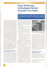
Picture 1: Tilting die retrofitting kit (entrance diameter 7,8 inch) equipped with two<br />
stepper drives mounted on a flat ground plate in order to test the achievable tilting angle<br />
Since the early days nearly nothing has<br />
changed concerning the method of<br />
mounting the die to the head and to centre<br />
it before the process is started. So it<br />
is not surprising that the technical solution<br />
which is still in use worldwide seems<br />
to be a little bit old-fashioned. Centring<br />
screws are positioned around the circumference<br />
of the head as long as the operator<br />
has free access to it. Heads for extrusion<br />
blow moulding often use special shifting<br />
systems especially when the access<br />
to the entire head is not possible. In addition<br />
to that these systems have to be<br />
operated manually when adjusting screws<br />
are used. This is not at all a convincing solution<br />
to meet the given technical requirements.<br />
List of requirements for the centring<br />
operation<br />
The requirements for an ideal solution are<br />
easy to formulate. The head has to be designed<br />
in a way that the die or the outer<br />
ring can only be mounted to the head in a<br />
centred position. In this case the head<br />
can immediately be heated up and the<br />
production can start without any delay after<br />
the die has reached the operating<br />
temperature. Skilled operating people<br />
might reply that it is necessary to move<br />
the die slightly out of the centre in order<br />
to achieve the best possible thickness<br />
distribution. This is the case as mostly the<br />
thickness distribution around the circumference<br />
is not good when the die is positioned<br />
exactly in the centre of the head.<br />
Consequently it is nevertheless necessary<br />
to adjust the position manually. This<br />
is indeed the case. But at least additional<br />
machine capacity would have been generated<br />
as a special centring operation will<br />
not be necessary any longer.<br />
Actually, in order to meet the requirements<br />
of the practical operation it has to<br />
be added that in spite of the compulsory<br />
centred mounting it must still be possible<br />
to sensitively correct the flow channel<br />
gap at the exit of the head in order to<br />
achieve the optimum result. This is due to<br />
the fact that each machine has some tiny<br />
deficiencies which disturb the homogeneous<br />
local velocity over the circumference<br />
of the head. As the necessary changes<br />
are rather small in practical operation<br />
the adjusting solution should take this into<br />
account. Especially with heads for the<br />
production of blown films which possess<br />
rather small flow channel gaps at the exit<br />
it would be of advantage if the gap could<br />
be changed in the range of 0.00004 inches.<br />
Additionally it would be ideal if it<br />
was possible to be able to reproduce any<br />
gap distribution which has been reached<br />
at an early time. Naturally it is also an important<br />
requirement that the solution<br />
should be realisable with small cost.<br />
Actual solution<br />
While rating the actual solution it must be<br />
realised that in the moment the above<br />
stated requirements are not at all fulfilled.<br />
The use of centring screws or shifting systems<br />
within a head does not allow for a<br />
close fit between the head and the die. As<br />
a consequence the die has either to be<br />
centred before the machine is put into<br />
operation or this has to be done while the<br />
line is running. In the first case this creates<br />
machine downtime. Additional scrap<br />
is processed in the second case. In both<br />
cases it goes without saying that qualified<br />
operators are necessary.<br />
The technical tools which are actually<br />
available for the operators are not at all<br />
convincing as well. To seal the shifting<br />
area of the head high normal forces are<br />
52 EXTRUSION 7/2010
necessary. That is why the clamping<br />
screws are dimensioned rather big. But<br />
threads of big screws have by nature<br />
great pitches. This is an obstacle for the<br />
postulated sensitive adjustment. As it is<br />
necessary first to create some tension to<br />
break the die free this problem is still enforced.<br />
This is the reason why the exact<br />
path the die has moved always remains<br />
unknown. As a consequence with the actual<br />
solution it is impossible to reproduce<br />
the situation which has existed before the<br />
adjustment. Due to that situation operators<br />
always stop their efforts to improve<br />
the situation before the possible optimum<br />
has been reached. Especially for thermal<br />
sensitive polymers it is also a problem<br />
that in the moment the die is shifted out<br />
of the centre dead zones are created in<br />
the flow channel.<br />
New solution to optimise the flow<br />
channel gap situation of an annular die<br />
Naturally attempts have been made to<br />
find a better technical solution. A construction<br />
can be found in the patent literature<br />
[1] where the die is not shifted but<br />
where a tilt joint is used. But the tilt joint<br />
construction proposed there affords a<br />
very precise manufacturing. Therefore it<br />
is rather expensive. That is the reason<br />
why it is hardly found in the market. The<br />
new solution also uses a tilt joint. What<br />
has changed is the form and the design of<br />
the tilt joint. Instead of the mechanical<br />
joint which is costly to manufacture an<br />
extreme cheap elastic tilt joint is used.<br />
Two stepper drives in linear configuration<br />
are mounted to the head in a 90 degree<br />
arrangement. The drives can realise adjustments<br />
as small as 0.00004 inches<br />
with an extreme precision due to the<br />
small steps and the additional transmission<br />
ration of the worm gear. Now it is<br />
possible to reproduce any situation or position<br />
which has been existed before an<br />
adjustment has been done.<br />
A close fit can be used while using a tilt<br />
solution as the die has no longer to be<br />
shifted relatively to the head. The big advantage<br />
is that the die by itself is centred<br />
immediately after it has been mounted to<br />
the head. A further advantage is that<br />
every existing annular head can be easily<br />
retrofitted with a tilt joint. Even an automatic<br />
adjustment is possible. To achieve<br />
this simply two stepper drives have to be<br />
attached to the head. Picture 1 shows a<br />
retrofitting kit for a blow moulding head<br />
during tilting test in the lab.<br />
Advantages of the use of a tilting die for<br />
different processes<br />
During the pipe extrusion it is no longer<br />
necessary to pre-centre the die after it<br />
has been dismantled for cleaning and<br />
attached to the line again. The optimisation<br />
of the thickness distribution around<br />
the circumference of the pipe can be<br />
done much more accurately. It is no longer<br />
necessary to use elongated tools to<br />
adjust the big conventional adjusting<br />
screws. The danger of injuries which<br />
exists with those manual adjustments is<br />
also eliminated.<br />
Using an elastic tilt joint no great forces<br />
are necessary. That is why normally four<br />
clamping screws are sufficient to fix the<br />
die to the head. They mainly have to carry<br />
the weight of the die apart from those<br />
dies where the flow channel diameter reduces<br />
from the entrance to the exit of the<br />
Picture 2: Head for the production of core<br />
foamed PVC-pipes (diameter 6.3 inch) that<br />
has been retrofitted with a tilt joint<br />
die. In this case naturally the forces generated<br />
by the pressure in the die have to be<br />
taken into account additionally.<br />
Picture 2 shows a head for the production<br />
of core foamed PVC pipes which possesses<br />
an elastic tilt joint. As the head<br />
has been retrofitted the conventional centring<br />
screws exist still. But these screws<br />
are no longer in use. To mount the die to<br />
the head only four of the original eight<br />
clamping screws have been used (see<br />
picture 2). This is the only hint that the<br />
head is equipped with a tilt joint. Fewer<br />
clamping screws promote a quicker assembling<br />
and disassembling of the die. In<br />
consequence not only cost for the line<br />
and the operators but also the resin cost<br />
can be saved. This is due to the fact that<br />
a better adjustment of the die immediately<br />
leads to a reduction of the thickness tolerances.<br />
So additionally at the same time<br />
also the quality of the extruded products<br />
is improved.<br />
The advantages described for the extrusion<br />
of pipes are more or less valid for the<br />
production of blown films. Additionally<br />
the last hindrance is eliminated which<br />
prevents an automatic start-up of blown<br />
film lines after the bubble has been built<br />
up. In the future the blown film head can<br />
be operated with a close-loop control<br />
which reduces not only the thickness differences<br />
over the circumference of the<br />
bubble but also the eccentric thickness<br />
distribution within the bubble. As a result<br />
the quality of the produced films is totally<br />
independent from the special skill of the<br />
line operator.<br />
During the pipe and blown film extrusion<br />
the head can be centred while the line is<br />
running. The same can be done while pro-<br />
Picture 3: Head mounted to a blow moulding<br />
machine equipped with a tilting joint<br />
which is actuated by stepper drives.<br />
54 EXTRUSION 7/2010
ducing small hollow parts using the extrusion<br />
blow moulding process. This is unfortunately<br />
no longer possible when the<br />
parts and consequently the machines become<br />
bigger. In this case the process has<br />
to be stopped. Often especially with older<br />
machines even he guard door has to be<br />
opened and the operator has to climb into<br />
the line between the opened tool to be<br />
able to adjust the die at all. The chief of<br />
production will not only profit from an improved<br />
security at his machine but also<br />
from an increased line capacity. This is<br />
due to the fact that the process has no<br />
longer to be stopped and afterwards a<br />
certain time is necessary until the machine<br />
has reached the steady state production<br />
situation again. During this time<br />
the machine produces scrap and precious<br />
production time gets lost. While using a<br />
head with a tilt joint which is actuated by<br />
stepper drives (see picture 3) this problem<br />
is eliminated totally.<br />
The biggest progress is achieved when<br />
using a tilt die for the production of blow<br />
moulded tubes which possess a bent. The<br />
tilt die first solves the wear problem<br />
which exists in the shifting area when<br />
using conventional x-y dies. Secondly, the<br />
tilt die is much cheaper in production<br />
compared to the actual solution. This is<br />
due to the fact that no high forces have to<br />
be overcome in the shifting area because<br />
small forces are necessary to tilt the die.<br />
Those forces can be realised with stepper<br />
drives which work with high precision,<br />
which are totally maintenance free and<br />
which nevertheless are rather cost efficient.<br />
Expensive servo valves and heavy<br />
hydraulic pistons with their hydraulic hoses<br />
become superfluous. No hydraulic<br />
unit is necessary in the case that electrically<br />
operated blow moulding machines<br />
are used, which are coming up increasingly.<br />
Future prospects<br />
Probably every existing annular head can<br />
be easily retrofitted with an elastic tilt<br />
joint. Of course, the relevant costs vary<br />
according to the size and the construction<br />
of the special head. For head diameters<br />
equal or smaller than 12 inches less than<br />
a five figured dollar amount will be probably<br />
sufficient. The economic advantage<br />
will naturally vary with the special application.<br />
The biggest profit can be achieved<br />
without doubt when a tilt head is used to<br />
produce tubes which have a bent. Such<br />
tubes are used widely in the automotive<br />
industry. In this case the tilt joint helps to<br />
centre the die statically and then it enables<br />
to tilt the die dynamically in order to<br />
profile the parison according to the needs<br />
of the tube which has to be produced. In<br />
regard of economics it is also of importance<br />
that it can be expected that tilt dies<br />
will need few maintenance and will not<br />
show wear problems. It depends on several<br />
individual internal factors of the relevant<br />
producer when the return on investment<br />
will be reached. After all a precise<br />
calculation of the economic value is<br />
consequently only possible when an existing<br />
conventional die is retrofitted with a<br />
tilt joint and when the achieved savings<br />
are determined in detail and then compared<br />
to the former situation.<br />
References<br />
1 Offenlegungsschrift DE 10 2005 026<br />
726 A1; Extrusionsblaskopf, date of<br />
submission 06.09.2005<br />
➠ <strong>Dr</strong>. <strong>Ing</strong>. <strong>Heinz</strong> Groß<br />
Kunststoff-Verfahrenstechnik<br />
Ringstr. 137, D-64380 Roßdorf, Germany<br />
Phone: +49 6154 695240; www.gross-k.de<br />
EXTRUSION 7/2010<br />
55