LEC 06 Shear Stresses for Beams in Bending(pdf) - KFUPM Open ...
LEC 06 Shear Stresses for Beams in Bending(pdf) - KFUPM Open ...
LEC 06 Shear Stresses for Beams in Bending(pdf) - KFUPM Open ...

You also want an ePaper? Increase the reach of your titles
YUMPU automatically turns print PDFs into web optimized ePapers that Google loves.
Chapter 4<br />
Load and Stress Analysis<br />
<br />
Lec. 6<br />
<strong>Shear</strong> <strong>Stresses</strong> <strong>for</strong> <strong>Beams</strong> <strong>in</strong> Bend<strong>in</strong>g<br />
A. Bazoune
4.8 <strong>Shear</strong> <strong>Stresses</strong> <strong>for</strong><br />
<strong>Beams</strong> <strong>in</strong> Bend<strong>in</strong>g<br />
Most beams have both shear <strong>for</strong>ces and bend<strong>in</strong>g moment<br />
present.<br />
It is only occasionally that we encounter beams subjected<br />
to pure bend<strong>in</strong>g, that is to say hav<strong>in</strong>g zero shear <strong>for</strong>ce.<br />
to pure bend<strong>in</strong>g, that is to say hav<strong>in</strong>g zero shear <strong>for</strong>ce.<br />
The flexural <strong>for</strong>mula was developed on the assumption of<br />
pure bend<strong>in</strong>g <strong>in</strong> order to elim<strong>in</strong>ate complicat<strong>in</strong>g effects of<br />
shear <strong>for</strong>ce.<br />
For eng<strong>in</strong>eer<strong>in</strong>g purposes, the flexure <strong>for</strong>mula is valid no<br />
matter whether the shear <strong>for</strong>ce is present or not.
Fig. 4.20 shows<br />
a beam of<br />
constant cross<br />
section<br />
subjected to a<br />
shear <strong>for</strong>ce V<br />
and a bend<strong>in</strong>g<br />
moment M<br />
Figure 4-20 Beam section isolation.<br />
Note: Only <strong>for</strong>ces <strong>in</strong> x-direction are<br />
shown on the dx element.
Associate the hollow<br />
vector with your<br />
right hand.<br />
If you place the<br />
thumb of your right<br />
hand <strong>in</strong> the negative<br />
z- direction, then<br />
your f<strong>in</strong>gers, when<br />
bent, will <strong>in</strong>dicate<br />
the direction of<br />
moment M.<br />
Figure 4-20 Beam section isolation.<br />
Note: Only <strong>for</strong>ces <strong>in</strong> x-direction are<br />
shown on the dx element.
<strong>Shear</strong> <strong>for</strong>ce and<br />
bend<strong>in</strong>g moment are<br />
related by:<br />
V<br />
=<br />
dM<br />
dx<br />
(a)<br />
Figure 4-20 Beam section isolation.<br />
Note: Only <strong>for</strong>ces <strong>in</strong> x-direction are<br />
shown on the dx element.
At some po<strong>in</strong>t<br />
along the beam,<br />
we cut transverse<br />
section dx at a<br />
distance y 1 above<br />
the neutral axis.<br />
<br />
We remove this<br />
section to study<br />
the <strong>for</strong>ces that act<br />
on it.<br />
Figure 4-20 Beam section isolation.<br />
Note: Only <strong>for</strong>ces <strong>in</strong> x-direction are<br />
shown on the dx element.
Because shear<br />
<strong>for</strong>ce is present,<br />
the B.M. is<br />
chang<strong>in</strong>g as we<br />
move along the x-<br />
axis.<br />
We can designate<br />
the B.M. as M on<br />
the Near Side of<br />
the section and as<br />
(M + dM) on the<br />
Far Side.<br />
Figure 4-20 Beam section isolation.<br />
Note: Only <strong>for</strong>ces <strong>in</strong> x-direction are<br />
shown on the dx element.
The moment M<br />
produces a normal<br />
stress σ, and the<br />
moment (M + dM),<br />
a normal stress<br />
(σ + dσ).<br />
These normal<br />
stresses produce<br />
normal <strong>for</strong>ces on<br />
the vertical faces of<br />
the element.<br />
The compressive <strong>for</strong>ce on the far side be<strong>in</strong>g<br />
greater than on the near side.<br />
The Resultant of these two would cause the<br />
section to tend to slide <strong>in</strong> the negative x-<br />
direction.
This resultant must<br />
be balanced by a<br />
shear <strong>for</strong>ce act<strong>in</strong>g<br />
<strong>in</strong> the positive x-<br />
direction on the<br />
bottom of the<br />
section.<br />
This shear <strong>for</strong>ce<br />
results <strong>in</strong> a shear<br />
stress.<br />
For the near face<br />
F<br />
N<br />
=∫<br />
c<br />
y<br />
1<br />
σ dA<br />
(b)<br />
where the limits <strong>in</strong>dicate that we <strong>in</strong>tegrate from y = y 1 to y = c.
σ = M y I<br />
For ,<br />
Eq. (b) becomes<br />
F<br />
N<br />
M<br />
=<br />
I<br />
∫<br />
c<br />
I ∫ ( )<br />
y<br />
1<br />
(b)<br />
y dA<br />
(c)<br />
For the Far side<br />
c M+<br />
dM c<br />
F = ∫ σ+ dσ<br />
dA = ∫ y dA<br />
y1 I y1<br />
(d)
The <strong>for</strong>ce on the<br />
bottom face is the<br />
shear stress τ times<br />
the area of the<br />
bottom face<br />
FB<br />
=τ bdx<br />
(e)
In this equation, the <strong>in</strong>tegral<br />
is the first moment of the<br />
area of the isolated vertical<br />
face about the neutral axis.<br />
∫<br />
c<br />
y y dA<br />
1<br />
=<br />
Q
The moment is usually designated Q<br />
Q<br />
∫ y dA=<br />
= c y<br />
1<br />
y'<br />
A'<br />
(4-30)<br />
where, <strong>for</strong> the isolated area from y 1 to c, is the distance from the<br />
y-axis to the area centroid and A’ is the area.<br />
F<strong>in</strong>ally, we write<br />
V Q<br />
τ =<br />
(4-31)<br />
I b
<strong>Shear</strong> <strong>Stresses</strong> <strong>in</strong> Standard-Section Section<br />
<strong>Beams</strong><br />
<br />
The shear stress distribution <strong>in</strong> a beam depends on how Q/b<br />
varies as a function of y 1.<br />
<br />
Fig. 4-22 shows a portion of a beam with a rectangular crosssection.<br />
It is subjected to shear <strong>for</strong>ce V and a bend<strong>in</strong>g Moment M.
Figure 4-22<br />
<strong>Shear</strong> Stress <strong>in</strong> a rectangular beam
A normal stress σ is developed on a cross-section such as A-A due to M.<br />
<br />
Section A-A is <strong>in</strong> compression above the N.A. and <strong>in</strong> tension below.
Consider an element of area dA at a distance<br />
y above the N.A. such that<br />
Eq. (4-30) becomes<br />
dA = bdy<br />
2<br />
c<br />
c by b<br />
Q y dA b y dy ⎡ ⎤<br />
= ∫ = c y<br />
y ∫ =<br />
1 y<br />
⎢ = −<br />
1 2<br />
⎥<br />
⎣ ⎦ 2<br />
c<br />
y1<br />
2 2<br />
( 1 )
Substitute this value <strong>in</strong>to Eq.(4-31)<br />
From Table A-18 and <strong>for</strong> a rectangular cross-section, we have<br />
Substitute A = bh and h = 2c<br />
gives<br />
Us<strong>in</strong>g this value <strong>for</strong> I <strong>in</strong> Eq. (4-32) gives<br />
V<br />
(<br />
2 2<br />
τ = c − y )<br />
(4-32)<br />
1<br />
2I<br />
I =<br />
Ac<br />
3<br />
3V<br />
⎛<br />
τ = ⎜1−<br />
2A<br />
⎝<br />
2<br />
I =<br />
bh<br />
12<br />
(b)<br />
(4-33)<br />
The maximum shear stress exists when y=0, which is at the bend<strong>in</strong>g<br />
neutral axis. Thus<br />
3V<br />
τ<br />
max<br />
=<br />
2A<br />
y<br />
c<br />
2<br />
1<br />
2<br />
⎞<br />
⎟<br />
⎠<br />
3<br />
(4-34)
As we move away from the neutral axis, the shear stress<br />
decreases parabolically until it is zero at the outer surface<br />
where y = ± c .<br />
Notice that the shear<br />
stress is maximum at<br />
the bend<strong>in</strong>g neutral<br />
axis, where the<br />
normal stress due to<br />
bend<strong>in</strong>g is zero and<br />
that the shear stress<br />
is zero at the outer<br />
surfaces, where the<br />
bend<strong>in</strong>g stress is a<br />
maximum.
Particular Case:<br />
<strong>Shear</strong> <strong>Stresses</strong> <strong>in</strong> Standard Section <strong>Beams</strong>
Example 4-7 Textbook<br />
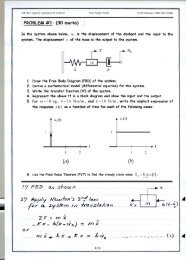
A beam 12 <strong>in</strong> long is to support a load of 488 lb.f act<strong>in</strong>g 3 <strong>in</strong> from the left<br />
support as shown <strong>in</strong> Fig- 4-21<br />
a. Bas<strong>in</strong>g the design only on bend<strong>in</strong>g stress, a<br />
designer has<br />
selected a 3-<strong>in</strong><br />
column<br />
channel with<br />
the cross-sectional<br />
sectional<br />
dimensions as shown. If the direct shear is neglected, the stress beam may be<br />
actually higher than the designer th<strong>in</strong>ks. DETERMINE the pr<strong>in</strong>cipal stresses<br />
consider<strong>in</strong>g bend<strong>in</strong>g and direct shear and compare then with that consider<strong>in</strong>g<br />
bend<strong>in</strong>g only.<br />
Figure 4-21.
Example 4-7 Cont’d<br />
The load<strong>in</strong>g, shear <strong>for</strong>ce and<br />
bend<strong>in</strong>g moment diagram are<br />
shown <strong>in</strong> Figure4-21(b)<br />
(b).<br />
If the direct shear <strong>for</strong>ce is<br />
<strong>in</strong>cluded <strong>in</strong> the analysis, the<br />
maximum stresses at the top<br />
and bottom of the beam will<br />
be the<br />
same<br />
as<br />
if only<br />
bend<strong>in</strong>g were<br />
considered.<br />
The maximum stresses are:<br />
Mc<br />
σ = ±<br />
I<br />
1098( 1.5)<br />
= ± = ± 992psi<br />
1.66<br />
Figure 4-21 (b).
Example 4-7 Cont’d
Example 4-7 Cont’d
y Q s t s ,s 1 2<br />
<strong>in</strong><br />
<strong>in</strong> 3<br />
psi<br />
psi<br />
psi<br />
0 0.653 0 847 847, -847<br />
0.25 0.648 165 840 762, -928<br />
0.5 0.631 331 818 670, -1000<br />
0.75 0.605 496 785 575, -1071<br />
1 0.568 661 737 477, -1138<br />
1.227 0.525 812 681 387, -1200<br />
1.5 0 992 0 0, -992