
Create successful ePaper yourself
Turn your PDF publications into a flip-book with our unique Google optimized e-Paper software.
Mo Di Mi Do Fr Sa So<br />
7<br />
14<br />
21<br />
28<br />
1 2 3<br />
8 9 10<br />
15 16 17<br />
22 23 24<br />
29 30 31<br />
4<br />
11<br />
18<br />
25<br />
5<br />
12<br />
19<br />
26<br />
6<br />
13<br />
20<br />
27<br />
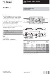
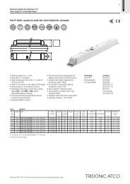
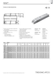
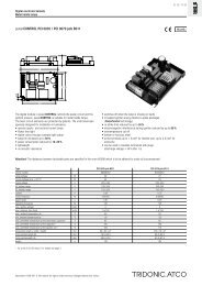
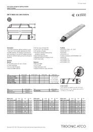
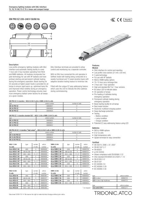
Emergency lighting modules with DALI interface<br />
T5, T8, TC-DD, TC-F, TC-L linear and compact lamps<br />
<strong>EM</strong> <strong>PRO</strong> <strong>EZ</strong> 220–240 V <strong>50</strong>/<strong>60</strong> <strong>Hz</strong><br />
RoHS<br />
21 mm<br />
self<br />
test<br />
boost<br />
start<br />
<strong>EZ</strong><br />
Address<br />
smart<br />
charging<br />
4<br />
30<br />
21<br />
280<br />
270<br />
Description:<br />
Low profile emergency lighting modules with DALI<br />
interface and automatic testing facility to cover<br />
1 hour and 3 hour duration operating from NiCd<br />
and NiMh batteries. All modules incorporate five<br />
pole technology for use with HF ballasts and have<br />
preheat starting and permanent cathode heating<br />
during the emergency operation. Boost starting for<br />
55 seconds at higher power levels is provided for all<br />
lamps to ensure rapid warm up, optimised lamp life<br />
and improved initial visibility during an emergency<br />
operation. Power control technology ensures maximum<br />
emergency ballast lumen factors for all lamps<br />
on a given module.<br />
DALI interface terminals are provided to allow<br />
control and monitoring via a seperate controller.<br />
With no DALI bus connected the unit operates in<br />
Selftest mode with testing being conducted on a<br />
weekly functional and 13 week duration basis with<br />
adaptive duration testing feature to minimise risk.<br />
Fitted with the unique <strong>EZ</strong> easy addressing feature<br />
which uses the LED to indicate the DALI address<br />
during commissioning.<br />
<strong>EM</strong> <strong>PRO</strong> <strong>EZ</strong> 3 h duration – NiCd 4.0 Ah D cells or NiMh 4.0 Ah Cs cells<br />
type article number number of cells<br />
<strong>EM</strong> 34 <strong>PRO</strong> <strong>EZ</strong> 89899827 4<br />
<strong>EM</strong> 35 <strong>PRO</strong> <strong>EZ</strong> 89899828 5<br />
<strong>EM</strong> 36 <strong>PRO</strong> <strong>EZ</strong> 89899829 6<br />
<strong>EM</strong> <strong>PRO</strong> <strong>EZ</strong> 1 h duration standard BLF – NiCd 1.5 Ah or NiMh 2.0 Ah Cs cells<br />
type article number number of cells<br />
<strong>EM</strong> 14 <strong>PRO</strong> <strong>EZ</strong> 89899830 4<br />
<strong>EM</strong> 15 <strong>PRO</strong> <strong>EZ</strong> 89899831 5<br />
<strong>EM</strong> 16 <strong>PRO</strong> <strong>EZ</strong> 89899832 6<br />
<strong>EM</strong> <strong>PRO</strong> HO <strong>EZ</strong> 1 h duration “high output” – NiCd 4.0 Ah D cells or NiMh 4.0 Ah Cs cells<br />
type article number number of cells<br />
<strong>EM</strong> 14 HO <strong>PRO</strong> <strong>EZ</strong> 89899833 4<br />
<strong>EM</strong> 15 HO <strong>PRO</strong> <strong>EZ</strong> 89899834 5<br />
<strong>EM</strong> 16 HO <strong>PRO</strong> <strong>EZ</strong> 89899835 6<br />
NiCd 1.5 Ah<br />
Cs cells<br />
NiCd 4.0 Ah<br />
D cells<br />
type<br />
type<br />
number<br />
of cells<br />
number<br />
of cells<br />
article<br />
number<br />
Accu-NiCd C 4A stick 4 89899692<br />
Accu-NiCd C 4B * side by side 4 89899693<br />
Accu-NiCd C 4C * stick + stick 2 + 2 89899694<br />
Accu-NiCd C 5A stick 5 89899695<br />
Accu-NiCd C 5B * side by side 5 89899696<br />
Accu-NiCd C 5C * stick + stick 3 + 2 89899697<br />
Accu-Nicd C 6A stick 6 89899698<br />
Accu-NiCd C 6C stick + stick 3 + 3 89899699<br />
article<br />
number<br />
Accu-NiCd 4A stick 4 89895961<br />
Accu-NiCd 4B side by side 4 89895977<br />
Accu-NiCd 4C stick + stick 2 + 2 89895978<br />
Accu-NiCd 5A stick 5 89895973<br />
Accu-NiCd 5B stick + stick 3 + 2 89895962<br />
Accu-NiCd 6A stick + stick 3 + 3 89895963<br />
NiMh 2.0 Ah<br />
Cs cells<br />
NiMh 4.0 Ah<br />
Cs cells<br />
type<br />
type<br />
number<br />
of cells<br />
number<br />
of cells<br />
article<br />
number<br />
Accu-NiMh C 4A stick 4 89899700<br />
Accu-NiMh C 4B * side by side 4 89899701<br />
Accu-NiMh C 4C * stick + stick 2 + 2 89899702<br />
Accu-NiMh C 5A stick 5 89899703<br />
Accu-NiMh C 5B * side by side 5 89899704<br />
Accu-NiMh C 5C * stick + stick 3 + 2 89899705<br />
Accu-NiMh C 6A stick 6 89899706<br />
Accu-NiMh C 6C stick + stick 3 + 3 89899707<br />
article<br />
number<br />
Accu-NiMh C 4A stick 4 898998<strong>50</strong><br />
Accu-NiMh C 5A stick 5 89899851<br />
Accu-NiMh C 6A stick 6 89899852<br />
Accu-NiMh C 6C stick + stick 3 + 3 89899853<br />
* on request<br />
Features:<br />
Module<br />
• DALI interface for control and reporting<br />
• Low profile cross section (21 mm x 30 mm)<br />
• 5 pole technology<br />
• For use with HF ballasts<br />
• NiCd or NiMh battey options<br />
• 10–15 hour accu recharge time<br />
• 3 hour and 1 hour operation<br />
• High and standard BLF for 1 hour versions<br />
• Bi-colour LED to indicate status<br />
• AC operation of lamps<br />
• Pre-heating of cathodes during<br />
emergency operation<br />
• Permanent cathode heating during<br />
emergency operation<br />
• Boost starting facility for all lamps<br />
• Rest mode function<br />
• Electronic multilevel charging system<br />
• Deep discharge protection<br />
• Testing<br />
– Battery condition<br />
– Lamp condition<br />
– Charge condition<br />
• Patented <strong>EZ</strong> easy addressing feature using LED<br />
Batteries<br />
• NiCd or NiMh options<br />
• D or Cs cells<br />
• High temperature cells<br />
• Spade terminals for easy connection<br />
Certified<br />
• EN 5<strong>50</strong>15: 2006 + A1: 2007<br />
• EN <strong>60</strong>1347-2-7<br />
• EN <strong>60</strong>925<br />
• pr IEC 62034<br />
• Allows compliance with EN <strong>60</strong>598-2-22<br />
• DALI standard EN <strong>60</strong>925 Ed 2/CDV v 1.12<br />
• EN 61000-3-2<br />
• EN 61547<br />
• IEC <strong>60</strong>068-2-6<br />
• IEC <strong>60</strong>068-2-29<br />
• IEC <strong>60</strong>068-2-30<br />
type<br />
article number<br />
LED bi-colour 89899720<br />
LED bi-colour high brightness 89899753<br />
type<br />
article number<br />
Test switch <strong>EM</strong> 2 89805277<br />
Data sheet 03/08-757-4 We reserve the right to make technical changes without prior notice.
Emergency lighting modules with DALI interface<br />
T5, T8, TC-DD, TC-F, TC-L linear and compact lamps<br />
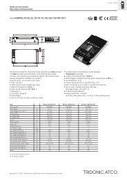
Technical data:<br />
<strong>EM</strong> <strong>PRO</strong> <strong>EZ</strong> 3 hour 1 hour<br />
Rated mains supply voltage 220–240 V 220–240 V<br />
Mains frequency <strong>50</strong>/<strong>60</strong> <strong>Hz</strong> <strong>50</strong>/<strong>60</strong> <strong>Hz</strong><br />
Mains supply current <strong>60</strong> mA max <strong>60</strong> mA max<br />
Mains supply power < 10.0 W < 10.0 W<br />
Overvoltage protection 320 V for 1 hour 320 V for 1 hour<br />
Max. working voltage U-OUT 4<strong>60</strong> V 4<strong>60</strong> V<br />
Recharge period 15 hours 10 hours<br />
Discharge current 1.1 A 1.1 A<br />
Charge current: Initial 330 mA 130 mA<br />
Fast 330 mA 210 mA<br />
Trickle 130 mA <strong>50</strong> mA<br />
Earth leakage current < 0.5 mA < 0.5 mA<br />
Ambient temperature range -5 °C to +<strong>60</strong> °C -5 °C to +<strong>60</strong> °C<br />
Maximum case temperature tc 70 °C 70 °C<br />
Mains change over voltage in accordance with in accordance with<br />
EN <strong>60</strong>598-2-22 EN <strong>60</strong>598-2-22<br />
Min. lamp starting temperature (emergency mode) -5 °C -5 °C<br />
Ingress protection IP20 IP20<br />
Safety class class I class I<br />
Function test 30 seconds 30 seconds<br />
via DALI command via DALI command<br />
Duration test 3 hr via 1 hr via<br />
DALI command<br />
DALI command<br />
Timer crystal controlled crystal controlled<br />
Boost starting time 55 seconds 55 seconds<br />
Testing:<br />
DALI Control<br />
A DALI command from a suitable control unit can be used to initiate function and<br />
duration tests at individually selected times. Status flags are set for report back and<br />
data logging of results.<br />
When a DALI bus is not connected or when a command has not been received the<br />
<strong>EM</strong> ... <strong>PRO</strong> <strong>EZ</strong> will operate in the self testing mode and will conduct tests in accordance<br />
with the default times stored in the EE<strong>PRO</strong>M. However it should be noted that in this case<br />
the delay time is set as default zero and all units could test at the same time. Test times<br />
can be changed with a command over the DALI bus.<br />
Addressing<br />
The <strong>EM</strong> <strong>PRO</strong> <strong>EZ</strong> includes the new <strong>EZ</strong> easy addressing system which allows addressing and<br />
identification by using the bi-colour LED in conjunction with the <strong>EZ</strong> <strong>PRO</strong> ADDRESS tool.<br />
Binary address codes given by the LED can be simply converted to the DALI addresses 0<br />
to 63. For single handed addressing using this method it is necessary to send a broadcast<br />
ident command every 3 to 9 seconds. During this command the main fluorescent lamp<br />
will be switched off and the LED will flash the 6 bit binary address preceded by a 3 second<br />
start indication period.<br />
Functional test<br />
The time of day and frequency of the 30 seconds function test can be set by the DALI<br />
controller. If the <strong>EM</strong> ... <strong>PRO</strong> <strong>EZ</strong> unit is not connected to a DALI bus or has not received a<br />
DALI command the test will default to 30 seconds duration on a weekly basis.<br />
Duration test<br />
Test times can be set by the DALI controller. If the <strong>EM</strong> ... <strong>PRO</strong> <strong>EZ</strong> unit is not connected<br />
to a DALI bus or has not received a DALI command the test will be conducted every<br />
13 weeks.<br />
Prolong time<br />
Prolong time can be set by the DALI controller. This is the delay time between return<br />
of the mains supply and the end of the emergency operation. The default prolong time<br />
is set as 2 minutes as specified within the DALI standard.<br />
Test switch<br />
An optional test switch can be wired to each <strong>EM</strong> ... <strong>PRO</strong> <strong>EZ</strong>. This can be used to to:<br />
• initiate a 30 seconds function test<br />
< 1 second press<br />
• adjust local timing when used in self test mode > 10 second press<br />
For a full description of the test swich function refer to application notes.<br />
DALI Controller<br />
DALI controllers and hardware/software solutions are available from<br />
TridonicAtco. Please refer to the Lighting controls section.<br />
Service life<br />
Average service life <strong>50</strong>,000 hours under rated conditions with a failure<br />
rate of less than 10 %. Average failure rate of 0.2 % per<br />
1000 operating hours.<br />
Accu-NiCd<br />
case temperature range 0 °C to +55 °C<br />
to ensure 4 years design life<br />
storage life in temperate conditions 4 years<br />
battery voltage<br />
1.2 V per cell<br />
capacity D<br />
4.0 Ah<br />
capacity Cs<br />
1.5 Ah<br />
Accu-NiMh 4.0 Ah<br />
case temperature range 0 °C to +<strong>50</strong> °C<br />
to ensure 4 years design life<br />
storage life in temperate conditions 4 years<br />
battery voltage<br />
1.2 V per cell<br />
capacity Cs<br />
4.0 Ah<br />
Accu-NiMh 2.0 Ah<br />
case temperature range 0 °C to +55 °C<br />
to ensure 4 years design life<br />
storage life in temperate conditions 4 years<br />
battery voltage<br />
1.2 V per cell<br />
capacity Cs<br />
2.0 Ah<br />
Mechanical details<br />
Channel manufactured from galvanised steel.<br />
Cover manufactured from white pre-coated steel.<br />
LED bi-colour status indicator<br />
• Green / red<br />
• Mounting hole 6.5 mm dia<br />
• Lead length 1000 mm<br />
Test switch<br />
• Mounting hole 7.0 mm dia<br />
• Lead length 5<strong>50</strong> mm<br />
Battery leads<br />
• Quantity: 1 red and 1 black<br />
• Length: 1300 mm<br />
• Wire type: 0.5 mm² solid conductor<br />
• Insulation rating: 90 °C<br />
Battery end termination<br />
Push on 4.8 mm receptacle to suit battery spade fitted with<br />
insulating cover<br />
Module end termination<br />
8.0 mm stripped insulation<br />
Two-piece batteries are supplied with a 200 mm lead with 4.8 mm<br />
receptacles at each end and insulating covers to connect the<br />
separate sticks together.<br />
Batteries<br />
Connection method: 4.8 x 0.5 mm spade tag welded to end of cell<br />
For stick packs this connection is accessible after the battery caps<br />
have been fitted.<br />
To inhibit inverter operation disconnect the batteries by removing<br />
the connector from the battery spade tag.<br />
For battery data see separate data sheet.<br />
2 Data sheet 03/08-757-4 We reserve the right to make technical changes without prior notice.
Emergency lighting modules with DALI interface<br />
T5, T8, TC-DD, TC-F, TC-L linear and compact lamps<br />
Status indication<br />
System status is indicated by a bi-colour LED and by a DALI status flag.<br />
LED<br />
Permanent green<br />
Fast flashing green<br />
Slow flashing green<br />
Permanent red<br />
Fast flashing red<br />
Slow flashing red<br />
Double pulsing green<br />
Status<br />
System OK<br />
Function test underway<br />
Duration test underway<br />
Lamp fault<br />
Charging fault<br />
Battery fault<br />
Rest mode<br />
Emergency light output factors (BLF) in %:<br />
Type<br />
TC-DD<br />
TC-SEL<br />
TC-DEL<br />
TC-TEL<br />
TC-F<br />
TC-L<br />
T5 FH<br />
T5 FQ<br />
T5 C<br />
T5<br />
T8<br />
10<br />
16<br />
21<br />
28<br />
38<br />
55<br />
5<br />
7<br />
9<br />
11<br />
10<br />
13<br />
18<br />
26<br />
18<br />
26<br />
32<br />
42<br />
57<br />
18<br />
24<br />
36<br />
18<br />
24<br />
36<br />
40<br />
55<br />
14<br />
21<br />
28<br />
35<br />
24<br />
39<br />
49<br />
54<br />
80<br />
22<br />
40<br />
55<br />
4<br />
6<br />
8<br />
13<br />
15<br />
18<br />
30<br />
36<br />
38<br />
58<br />
70<br />
<strong>EM</strong> 34<br />
<strong>PRO</strong> <strong>EZ</strong><br />
37<br />
25<br />
19<br />
14<br />
40<br />
39<br />
39<br />
34<br />
31<br />
26<br />
21<br />
14<br />
21<br />
14<br />
18<br />
18<br />
24<br />
13<br />
14<br />
38<br />
43<br />
40<br />
27<br />
20<br />
16<br />
12<br />
10<br />
3 hours 1 hour<br />
<strong>EM</strong> 35 <strong>EM</strong> 36 <strong>EM</strong> 14 <strong>EM</strong> 15<br />
<strong>PRO</strong> <strong>EZ</strong> <strong>PRO</strong> <strong>EZ</strong> <strong>PRO</strong> <strong>EZ</strong> <strong>PRO</strong> <strong>EZ</strong><br />
11<br />
12<br />
11<br />
12<br />
11<br />
5<br />
16<br />
10<br />
8<br />
10<br />
4<br />
7<br />
5<br />
6<br />
14<br />
12<br />
8<br />
6<br />
6<br />
5<br />
7<br />
7<br />
6<br />
37<br />
25<br />
19<br />
14<br />
40<br />
39<br />
39<br />
34<br />
31<br />
26<br />
21<br />
14<br />
21<br />
14<br />
18<br />
18<br />
24<br />
13<br />
14<br />
38<br />
43<br />
40<br />
27<br />
20<br />
16<br />
12<br />
10<br />
11<br />
12<br />
11<br />
12<br />
11<br />
5<br />
16<br />
10<br />
8<br />
<strong>EM</strong> 16<br />
<strong>PRO</strong> <strong>EZ</strong><br />
10<br />
4<br />
7<br />
5<br />
6<br />
14<br />
12<br />
8<br />
6<br />
6<br />
5<br />
7<br />
7<br />
<strong>EM</strong> 14 HO<br />
<strong>PRO</strong> <strong>EZ</strong><br />
53<br />
53<br />
53<br />
53<br />
51<br />
47<br />
34<br />
27<br />
36<br />
25<br />
19<br />
32<br />
32<br />
47<br />
30<br />
30<br />
70<br />
73<br />
68<br />
52<br />
36<br />
33<br />
27<br />
23<br />
1 hour “high output”<br />
<strong>EM</strong> 15 HO<br />
<strong>PRO</strong> <strong>EZ</strong><br />
28<br />
24<br />
33<br />
26<br />
33<br />
26<br />
24<br />
44<br />
18<br />
<strong>EM</strong> 16 HO<br />
<strong>PRO</strong> <strong>EZ</strong><br />
19<br />
21<br />
42<br />
36<br />
31<br />
22<br />
23<br />
15<br />
27<br />
23<br />
Data sheet 03/08-757-4 We reserve the right to make technical changes without prior notice.<br />
3
Emergency lighting modules with DALI interface<br />
T5, T8, TC-DD, TC-F, TC-L linear and compact lamps<br />
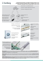
Electrical connections:<br />
An earthed starting aid is recommended. The<br />
module should be earthed by the fixings used to<br />
attach it to the luminaire.<br />
Wiring:<br />
Lamp/ballast/supply<br />
wire preparation:<br />
0.5–0.75<br />
8–9 mm<br />
IDC interface<br />
• solid wire with a cross section of 0.5 mm²<br />
according to the specification from WAGO<br />
• alternatively a flexible lead with a cross section<br />
of 0.75 mm²<br />
Horizontal interface<br />
• solid wire with a cross section of 0.5–0.75 mm²<br />
according to the specification from WAGO<br />
• solid wire with a cross section of 1.0 mm² with<br />
an insulation diameter up to 2.5 mm<br />
• strip 9 mm of insulation from the cables<br />
• Loosen wire through twisting and pulling<br />
Batteries/LED/Test switch<br />
push terminal with button release: 0.5 mm²<br />
6.5 mm strip<br />
Maximum lamp lead capacitance<br />
terminals 5 and 6 (* hot leads) 100 pF 1)<br />
terminals 3 and 4 200 pF 1)<br />
1)<br />
Note: care should be taken not to exceed the total maximum<br />
lamp lead capacitance for HF ballast. Leads should always be<br />
kept as short as possible.<br />
Loosen wire through<br />
twisting and pulling<br />
Wiring guidelines<br />
To ensure that a luminaire containing high frequency<br />
emergency units complies with EN 5<strong>50</strong>15 for radio<br />
frequency conducted interference in both normal and<br />
emergency mode it is essential to follow good practice<br />
in the wiring layout.<br />
Within the luminaire the switched and unswitched<br />
<strong>50</strong> <strong>Hz</strong> supply wiring must be routed as short as<br />
possible and be kept as far away as possible from<br />
the lamp leads.<br />
This means, for example, in a linear T8 or T5 luminaire<br />
the mains wiring should be routed along one side of<br />
the luminaire body, while the wires to the emergency<br />
lamp from the emergency module are routed along the<br />
other side.<br />
The high frequency emergency lamp wiring contains<br />
“hot” leads at pins 1 and 6, which have high voltage<br />
to earth. These should be kept as short as possible<br />
and separated from other wiring to minimize coupling.<br />
They also have a restriction on capacitance to other<br />
wiring and earth of 100 pF, which must be observed to<br />
ensure good lamp starting.<br />
With an earth connection of the metal case of the<br />
emergency module the noise suppression can be<br />
further improved. The wiring of the earth should be<br />
kept as short as possible.<br />
Through wiring may affect the emc performance of<br />
the luminaire.<br />
With the use of the fifth pole possible compatibility<br />
problems between the products can be prevented.<br />
Depending on the luminaire wiring the radio suppression<br />
in the emergency mode of operation can be<br />
further improved.<br />
Capacitive loading limits of lamp leads must not be<br />
exceeded. Note the capacitance of the emergency<br />
lamp leads adds to the capacitance of the leads from<br />
the ballast to the <strong>EM</strong> BASIC module when considering<br />
ballast loading.<br />
The LED and test switch wiring should be routed<br />
separately and kept as far away as possible from<br />
the high frequency lamp leads to avoid coupling.<br />
4 Data sheet 03/08-757-4 We reserve the right to make technical changes without prior notice.
Emergency lighting modules with DALI interface<br />
T5, T8, TC-DD, TC-F, TC-L linear and compact lamps<br />
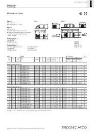
<strong>EM</strong> ... <strong>PRO</strong> <strong>EZ</strong> emergency module wiring diagrams<br />
Not for use with magnetic ballasts and switch start circuits<br />
Switched line out to ballast<br />
Line in from switch<br />
Neutral<br />
DALI control<br />
DALI control<br />
Permanent line<br />
Lout<br />
Lin<br />
N<br />
D1<br />
D2<br />
L<br />
+<br />
LED<br />
LED<br />
–<br />
Switch<br />
<strong>EM</strong> ... <strong>PRO</strong> <strong>EZ</strong><br />
<strong>EM</strong>ERGENCY MODULE<br />
8<br />
7<br />
6<br />
5<br />
4<br />
3<br />
2<br />
1<br />
Emergency lamp<br />
Optional<br />
Test<br />
Switch<br />
orange (+)<br />
LED<br />
pink (–)<br />
Battery<br />
Optional<br />
Test<br />
Switch<br />
orange (+)<br />
LED<br />
pink (–)<br />
Battery<br />
Neutral to ballast<br />
L<br />
N<br />
Neutral to ballast<br />
L<br />
N<br />
HF BALLAST<br />
U-OUT max. 4<strong>60</strong> V<br />
HF BALLAST<br />
U-OUT max. 4<strong>60</strong> V<br />
* Hot leads<br />
* Hot leads<br />
Lamp<br />
Wiring diagram for single lamp high frequency ballasts<br />
Wiring diagram for twin lamp high frequency ballasts with 6 terminals<br />
Switched line out to ballast<br />
Line in from switch<br />
Neutral<br />
DALI control<br />
DALI control<br />
Permanent line<br />
Lout<br />
Lin<br />
N<br />
D1<br />
D2<br />
L<br />
+<br />
LED<br />
LED<br />
–<br />
Switch<br />
<strong>EM</strong> ... <strong>PRO</strong> <strong>EZ</strong><br />
<strong>EM</strong>ERGENCY MODULE<br />
8<br />
7<br />
6<br />
5<br />
4<br />
3<br />
2<br />
1<br />
Emergency lamp<br />
Optional<br />
Test<br />
Switch<br />
orange (+)<br />
LED<br />
pink (–)<br />
Battery<br />
Optional<br />
Test<br />
Switch<br />
orange (+)<br />
LED<br />
pink (–)<br />
Battery<br />
Neutral to ballast<br />
L<br />
N<br />
Neutral to ballast<br />
L<br />
N<br />
HF BALLAST<br />
U-OUT max. 4<strong>60</strong> V<br />
HF BALLAST<br />
U-OUT max. 4<strong>60</strong> V<br />
Lamp<br />
Lamp<br />
* Hot leads<br />
* Hot leads<br />
Wiring diagram for twin lamp high frequency ballasts with 7 terminals<br />
Wiring diagram for twin lamp high frequency ballasts with 8 terminals<br />
No connection to be made<br />
Neutral<br />
DALI control<br />
DALI control<br />
Permanent line<br />
Lout<br />
Lin<br />
N<br />
D1<br />
D2<br />
L<br />
+<br />
LED<br />
LED<br />
–<br />
Switch<br />
<strong>EM</strong> ... <strong>PRO</strong> <strong>EZ</strong><br />
<strong>EM</strong>ERGENCY MODULE<br />
8<br />
7<br />
6<br />
5<br />
4<br />
3<br />
2<br />
1<br />
Emergency lamp<br />
Addressing Tool<br />
An addressing tool is available to convert the LED binary identification signal<br />
to a DALI address of between 0 to 63. This simple tool is powered from a 9 V<br />
battery (not supplied).<br />
Optional<br />
Test<br />
Switch<br />
orange (+)<br />
LED<br />
pink (–)<br />
Battery<br />
* Hot leads<br />
Wiring diagram for non-maintained operation<br />
Note: All hot leads normally marked with an * should be kept as short as possible.<br />
For comprehensive wiring diagrams and instructions consult the TridonicAtco website<br />
www.tridonicatco.com<br />
Packing quantities:<br />
<strong>EM</strong> ... <strong>PRO</strong> <strong>EZ</strong>:<br />
25 units per carton<br />
Bi-colour LED:<br />
25 pieces per bag<br />
Accu NiCd:<br />
25 pieces per box<br />
Accu NiMh:<br />
25 pieces per box<br />
<strong>EZ</strong> <strong>PRO</strong> ADDRESS: 89899836<br />
Data sheet 03/08-757-4 We reserve the right to make technical changes without prior notice.