controls
controls
controls

You also want an ePaper? Increase the reach of your titles
YUMPU automatically turns print PDFs into web optimized ePapers that Google loves.
CONTROLS<br />
Control Components<br />
8008 CONTROL SWITCHES<br />
APPROVALS<br />
FILE No. E182378<br />
CERTIFIED - FILE No. LR99480<br />
PTB 00 ATEX 1111U<br />
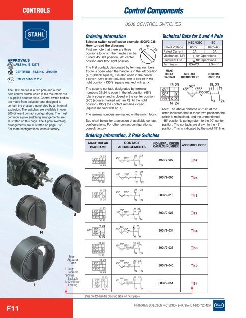
The 8008 Series is a two pole and a four<br />
pole control switch which is rail mountable via<br />
a supplied adapter plate. Control switch bodies<br />
are made from polyester and designed to<br />
contain the pressure generated by an internal<br />
explosion. The switches are available in over<br />
300 different contact configurations. The most<br />
common 2-pole switching arrangements are<br />
illustrated on this page. The 4 pole switching<br />
arrangements are illustrated on page F12.<br />
For more configurations, consult factory.<br />
Ordering Information<br />
Selector switch specification example: 8008/2-038<br />
How to read the diagram:<br />
90˚<br />
First we note that there are three<br />
positions to which the handle can be<br />
turned: 45° left position, 90° center<br />
position and 135° right position.<br />
The first contact, designated by terminal MAKE numbers<br />
BREAK CONTACT<br />
13-14 is open when the handle is DIAGRAM in the ARRANGEMENT left position<br />
45° 135°<br />
13 23<br />
(45°) [blank square], it is also open 13 in 14the center ° °<br />
23 24<br />
°<br />
14<br />
°<br />
24<br />
position (90°) [blank square], and is 90° closed in the<br />
right position (135°) [square marked with an X].<br />
The second contact, designated by terminal<br />
numbers 23-24 is open in the left position (45°)<br />
[blank square] and is closed in the center position<br />
(90°) [square marked with an X]. At the right<br />
position (135°) the contact remains closed<br />
[square marked with an X].<br />
The terminal numbers are marked on the switch block.<br />
See chart below for a selection of available contact<br />
configurations. For other contact configurations,<br />
consult factory.<br />
Ordering Information, 2 Pole Switches<br />
MAKE BREAK<br />
DIAGRAMS<br />
45˚<br />
CONTACT<br />
ARRANGEMENTS<br />
135˚<br />
Technical Data for 2 and 4 Pole<br />
Rated Voltage<br />
Rated Current<br />
Mechanical Life<br />
Electrical Life<br />
Terminals<br />
INDIVIDUAL ORDER<br />
CATALOG NUMBER<br />
NEC/CEC<br />
600V<br />
10A<br />
IEC<br />
690VAC<br />
10A<br />
> 10 5 Operations<br />
> 10 5 Operations<br />
12AWG 2.5mm 2<br />
MAKE<br />
BREAK CONTACT ORDERING<br />
038DIAGRAM ARRANGEMENT CODE 038<br />
ORDERING<br />
CODE<br />
Note: The above denoted 45°/90° at the<br />
notch indicates that in these two positions the<br />
switch is maintained, and the unmentioned<br />
135° position is spring return to the 90° center<br />
position. The contacts are drawn in the 45°<br />
position. This is indicated by the solid 45° line.<br />
ASSEMBLY CODE<br />
8008/2-002<br />
❐02<br />
8008/2-005<br />
❐05<br />
8008/2-016<br />
❐16<br />
S<br />
8008/2-027<br />
❐27<br />
N<br />
8008/2-034<br />
❐34<br />
8008/2-038<br />
❐38<br />
L<br />
Insert<br />
Actuator<br />
Code<br />
L-Large<br />
Lockable<br />
S-Small<br />
Lockable<br />
N-Small Non-<br />
Locking<br />
8008/2-040<br />
8008/2-051<br />
❐40<br />
❐51<br />
(See Switch handle ordering table on next page).<br />
F11<br />
INNOVATIVE EXPLOSION PROTECTION by R. STAHL 1-800-782-4357